
After the long thread on weak DCS output signals from the TIUs there was some interest in a simpler tester for those that don't want to finance or support a full oscilloscope. Here is a really simple $10 answer (I priced parts at $9.44 on digikey... battery not included!).

DCS_test1

Concept:

It's super simple. The filter [A] extracts the DCS packet. The offset diode [B] makes the voltage go between 0 and 12V (instead of -6V to +6V). The trimpot [C] is a voltage divider and makes it so the DCS amplitude needs to be about 12V to successfully trigger the one-shot. The one-shot pules a blue LED [E] for 1 second set by time base [D]. It runs off a 9V battery that's regulated. [F]

How to use it:

Connect the red and black wires to the TIU port. If the TIU port is good (Vdcs > 12V), the LED will blink. If the TIU port is weak/broken/bad (Vdcs < 12V) the LED will not blink.

I made a breadboard version and it works well. I'm a designer but maybe someone who's both a designer and good at making things (so basically GRJ) might do a pcb with a box if there is interest.

Attachments

Images (1)
  • DCS_test1
Last edited by Adrian!
Original Post

Replies sorted oldest to newest

Thanks for posting this!

So to set the trim pot, do we set it up on a TIU output we have reason to believe is good and just adjust the pot until the LED starts blinking?  Or is there a better method during construction (maybe applying a DC  signal directly to the B/C node of the circuit before installing the filters on the front end?)?

Thanks for all the good discussions you have been posting on the topic.

-Dave

Dave45681 posted:

Thanks for posting this!

So to set the trim pot, do we set it up on a TIU output we have reason to believe is good and just adjust the pot until the LED starts blinking?  Or is there a better method during construction (maybe applying a DC  signal directly to the B/C node of the circuit before installing the filters on the front end?)?

Thanks for all the good discussions you have been posting on the topic.

-Dave

Hey!

Yup, the trimpot just sets how many volts of dcs signal you need before the light flashes. If you turn it all the way up it’ll flash at 2.5V. In the middle it would flash at 5V. Near the top maybe 50V or more. I think it’s easiest to just tune it against a good channel like you suggest. Tune it to the point right where it barely flashes on a working channel, then leave it set there as your threshold of good and bad for future tests.

Last edited by Adrian!

I would like to try this out. Not sure I can make a PCB? If so that would take me some time, but I might try it anyway? Breadboard is probably what I will start with. I know GRJ can probably put one out in a few minutes. He may even have one posted here by the time I post this? 

My only question (I think) would be what type of caps did you use and were the resistors precision or just regular old 5% resistors? I am going to place a Digikey order for all that I don't have. Or maybe just order it all along with some extras.

Thank you again Adrian, for doing all this stuff and posting here for the rest of us. I find it all very interesting, make that fascinating! As I have said before most is over my head, but still very interesting and some may even rub off on me one of these days. 

Last edited by rtr12
rtr12 posted:

I would like to try this out. Not sure I can make a PCB? If so that would take me some time, but I might try it anyway? Breadboard is probably what I will start with. I know GRJ can probably put one out in a few minutes. He may even have one posted here by the time I post this? 

My only question (I think) would be what type of caps did you use and were the resistors precision or just regular old 5% resistors? I am going to place a Digikey order for all that I don't have. Or maybe just order it all along with some extras.

Thank you again Adrian, for doing all this stuff and posting here for the rest of us. I find it all very interesting, make that fascinating! As I have said before most is over my head, but still very interesting and some may even rub off on me one of these days. 

Hey!

The RC network at the front blocks 60Hz and keeps 1 MHz. Even if the values were off a factor of 10 times it should work fine. The filter as drawn cutsoff signals below a few KHz, but 10Khz or 100Khz is also fine. The r and c for the timebase sets the light flash at about a second. Depending on which version of 74h123 you buy the equation for the duration is different so you may want to try different combinations until you’re happy with it.

RJR posted:

Adrian, going to Digikey, I see many variations of the CD74HC123.  Why the differences and which is best?  Note Adrian asked a question about resistors & caps.

Hi again... I went with exactly this chip. There's no design reason, it was just in stock the week I needed it. All the people who make 74xx chips (TI, ADI, ON, ...) have different underlying fabrication processes for the CMOS technology so you get different timing numbers depending on which brand you buy. Again on the resistors and caps 5% should be more than enough. Everything is order of magnitude-ish insensitive so if you buy 1K,5K,10K,100K resistors and 0.01uF, 0.1uF, and 1uF caps, you will definitely have a few combinations that work. The only one that's critical is the one for the LED so you don't blow it with too much current.Note the LED doesn't have to be blue.... I just think they look fancy.

Engineer-Joe posted:

just to be clear here, you're just testing for +12volts out?

Most users will know if the TIU doesn't put out voltage. Is there a condition you're looking at that puts out partial voltages?

A meter or MTH PS2 or 3 engine could tell the user what the track voltage is.... right? or even a light bulb?

Adrian talks about DCS signal in volts not to be confused with volts used to run an engine. 

He should be able to explain it better

Engineer-Joe posted:

just to be clear here, you're just testing for +12volts out?

Most users will know if the TIU doesn't put out voltage. Is there a condition you're looking at that puts out partial voltages?

A meter or MTH PS2 or 3 engine could tell the user what the track voltage is.... right? or even a light bulb?

Here's a little doodle I made just for you!

voltage

The track has a 60 Hz voltage to power the trains (usually like 10-25V depending on what power source and such). It also has super-imposed on top of that the digital signal for DCS. We are talking about measuring this digital voltage, not track voltage. The digital packets are infrequent and at a high frequency which is why you need to filter them with the above circuit to measure them independently of track power.  It's this DCS digital voltage (formal name is excursion voltage) that limits your DCS link quality. A normal working part should have it about 12-14V, but when parts fail it can be a lot less. This is what the tester is validating.

Attachments

Images (1)
  • voltage

Digikey parts ordered! Luckily, I selected the exact CD74HC123E chip as Adrian linked above too! I didn't get the assortment of resistors and caps, but I have those in quite a few different values here in ceramic caps and 5% 1/4 & 1/2 watt resistors. Oh dear, now for the PCB design...eek! I think GRJ uses Diptrace, so I'll try using that. Maybe he will have mercy on me with this project if it's in his native language? 

What would be cool here is several LED's so you could see lower values.  If this were assembled by someone with a 'scope to calibrate it, you could have maybe four LED's to know exactly what you have.  What would probably be easy would be to create a circuit board for such a design with thru-hole parts so many people could build it.  With a 1% divider, you could probably do this kind of thing that requires no calibration.

gunrunnerjohn posted:

What would be cool here is several LED's so you could see lower values.  If this were assembled by someone with a 'scope to calibrate it, you could have maybe four LED's to know exactly what you have.  What would probably be easy would be to create a circuit board for such a design with thru-hole parts so many people could build it.  With a 1% divider, you could probably do this kind of thing that requires no calibration.

I like it ... but then you need 4 one-shots, 4 dividers and 4 leds to do it using this approach. If you only want one led at a time you need a thermometer decoder too.

If you're going to all this trouble you might just give up and and go to a microcontroller with an 8-bit ADC inside and a $10 LCD with numbers on it (like my telemetry train one). That's closer to a $50 solution though. At some point writing code becomes simpler than so much analog!

Everything I ordered was Thru-Hole so if I make it out alive after getting into Diptrace it will be something most anyone can make. I don't have a scope, nor would I know how to use it if I did so the calibration is a bit above me right now. I would be happy to add more LEDs, if I get something made up without getting spanked by the PCB part. 

I also ordered extras of each part so I could fiddle a bit with the boards if I get that far that is.

Adrian! posted:
gunrunnerjohn posted:

What would be cool here is several LED's so you could see lower values.  If this were assembled by someone with a 'scope to calibrate it, you could have maybe four LED's to know exactly what you have.  What would probably be easy would be to create a circuit board for such a design with thru-hole parts so many people could build it.  With a 1% divider, you could probably do this kind of thing that requires no calibration.

I like it ... but then you need 4 one-shots, 4 dividers and 4 leds to do it using this approach. If you only want one led at a time you need a thermometer decoder too.

If you're going to all this trouble you might just give up and and go to a microcontroller with an 8-bit ADC inside and a $10 LCD with numbers on it (like my telemetry train one). That's closer to a $50 solution though. At some point writing code becomes simpler than so much analog!

I'm not convinced that you really need four one-shots.  Why not a comparator ladder with four levels?  An LED will be visible with a very short pulse, so the one-shot may just be icing on the cake to make it even more visible.  I'd consider 3V, 6V, 9V, and 12V.  Something cheap like the LM3900 and a resistor divider ladder driving an LED on each output. 

Quaere:  As I understand this gizmo, if the TIU signal voltage falls below a certain point, the LED flashes.  If this could be done, wouldn't it also be relatively feasible to have it provide an output voltage readable with a voltmeter or a milliammeter, so one could have an idea of relative signal strength????

gunrunnerjohn posted:

I'm not convinced that you really need four one-shots.  Why not a comparator ladder with four levels?  An LED will be visible with a very short pulse, so the one-shot may just be icing on the cake to make it even more visible.  I'd consider 3V, 6V, 9V, and 12V.  Something cheap like the LM3900 and a resistor divider ladder driving an LED on each output. 

You're basically describing making a low res flash ADC which is actually what I thought about too before going with the one shot. 

It can be made to work but there's a lot of problems to struggle through. The trickiest part is the comparator itself because it's level sensitive, not edge sensitive, meaning if the input keeps changing, the output of the comparator immediately tries to respond to the change with its limited slew rate.

For example the LM3900 on page 3 is specified have a slew rate "SR" of 0.5V/us low to high output and 20V/us high to low.

The start of the DCS code is like 10111010... and each bit is like 0.3us long...

So the comparator will go up for 0.3 u-seconds at that slew rate and arrive at 0.5V x 0.3us = 0.165V. Then it will go down for 0.3us at 20V/us to about -6V. Then it will go up for 3x0.3us at the 0.5V/us rate to -6 + (0.3us X 3bits X 0.5V/us) = -5.55V. That means the set of 4 won't respond to the levels quite the way you think (it won't be like a comparator at DC). This is because the comparator slew rate can't keep up with the internal speed of the transitions inside the DCS packet.

This shows we need a comparator with slew rate that gets to the LED turn on voltage (or reliably exceeds threshold voltage of a following gate) within about half the bit time. (Roughly 3-4V/0.15us = 25V/us). Clearly this won't be a PDIP package, so it makes prototyping hard since you pretty-much need a custom PCB.  Also you're on a battery so you want a single-supply comparator if possible.

I think you can figure it out, but it might take a bit of work to get it reliable.

RJR posted:

Quaere:  As I understand this gizmo, if the TIU signal voltage falls below a certain point, the LED flashes.  If this could be done, wouldn't it also be relatively feasible to have it provide an output voltage readable with a voltmeter or a milliammeter, so one could have an idea of relative signal strength????

It's possible to do this, but it's tricky and won't be $10 any more. The DCS packets are short and infrequent so it's hard to turn them into a DC voltage large enough to measure with good resolution. I recorded an add engine DCS exchange and rectified it in spice with an ideal diode. The whole exchange gets you only like 20mV of DC. That means you need sampling-and-hold circuits to hold the voltage long enough to measure it (the packet it too short!) as well as amps and filtering.

GRJ is talking about a 4 LED system (red, yellow, green, blue?) that is similar. Again it's possible and makes sense but needs lots of design work.

The version at the top is just the very-economical and simple to use yes or no device which is what some folks were asking for. The high end version is like the AGHR T-train.

Adrian, your "high end" is only for a select few, most folks won't go that far.  I'm thinking of a tool that's perhaps more expensive than the $10 version, but parts would certainly be no more than around $20.  However, you make a good point, we may need to re-think the comparator speed, that will run the cost up somewhat, but not out of reason.  The LM397 looks to be a reasonable choice.  Obviously, as you say, it's a surface mount package, looks like that's a given.

Last edited by gunrunnerjohn
gunrunnerjohn posted:

Adrian, your "high end" is only for a select few, most folks won't go that far.  I'm thinking of a tool that's perhaps more expensive than the $10 version, but parts would certainly be no more than around $20.  However, you make a good point, we may need to re-think the comparator speed, that will run the cost up somewhat, but not out of reason.

I like a medium solution also. Here's a comparator that would work well for this that I looked at. I didn't want to deal with making a PCB though.

Actually, the MAX912 dual is $6.50, so that's $13 right there.   They do have a latching output, maybe something clever there to extend the light output if the pulse is too brief.  Nothing immediately springs to mind, but it's something that might make sense.  Perhaps one single shot that is driven off the lowest voltage output to latch the indication for a short time period?

Making a PCB is the easy part, and if you keep it fairly small, it's even pretty cheap.

Last edited by gunrunnerjohn

Poorly.  The signal strength in the locomotives simply measures how many good packets vs bad packets it gets for a test stream.  Depending on the circumstances, it could be getting all good with low voltage from the TIU.  Also, as we all know, a good TIU with bad wiring/track layout will yield bad results.

This is a tool to test the TIU independently.

Last edited by gunrunnerjohn
gunrunnerjohn posted:

Poorly.  The signal strength in the locomotives simply measures how many good packets vs bad packets it gets for a test stream.  Depending on the circumstances, it could be getting all good with low voltage from the TIU.  Also, as we all know, a good TIU with bad wiring/track layout will yield bad results.

This is a tool to test the TIU independently.

Actually, since we’ve been talking about lengths.... the MTH signal test also uses a very short test packet like the length of a speed command (about 500us), so it’s skewed to be very optimistic and doesn’t inform the situation for longer commands like adding engines or app reads

Engineer-Joe posted:

Do you like to use the protocast feature to play music thru the engine for a test?

If the music doesn't play clearly it shows weak signal?

Doesn't that show good signal strength? (full use of test packets?)

I’m not sure about this. I need to look into how protocast encodes the audio. It might just send the audio in small chunks. Plus the Audio is 16bit so just because it sounds okay doesn’t mean all the bits are correct. Let me take a look at the details and I’ll let you know 

Last edited by Adrian!

Again Joe, unless you're doing this on a test bench with the layout and wiring out of the picture, you're not really testing the TIU functionality, you're testing the whole layout.  The object of this exercise, at least what I thought it was, is to test the TIU to insure it's putting out a good signal. 

When you get into testing the layout, that's a whole other matter, and lots of variables suddenly come into play.

Also, when running the test on the bench, you're likely to get good results even with a bad TIU channel, as you don't have all the layout and wiring to dilute your signal.


Adrian! posted:
gunrunnerjohn posted:

Poorly.  The signal strength in the locomotives simply measures how many good packets vs bad packets it gets for a test stream.  Depending on the circumstances, it could be getting all good with low voltage from the TIU.  Also, as we all know, a good TIU with bad wiring/track layout will yield bad results.

This is a tool to test the TIU independently.

Actually, since we’ve been talking about lengths.... the MTH signal test also uses a very short test packet like the length of a speed command (about 500us), so it’s skewed to be very optimistic and doesn’t inform the situation for longer commands like adding engines or app reads

https://ogrforum.ogaugerr.com/...-signal-stregth-test

I think I knew this before I asked?

Again, thank you for the time to explain things.

Last edited by Engineer-Joe

Well Adrian, as if you are bored with nothing better to do, could you look at the signal packet for a large consist of engines and determine just how much longer the packets are for them vs. a single engine?

 There were times I could get great response from running a single engine around the track. Then it would seem like "all hell broke loose" when I built a big train. MTH posted that running a big consist took more info to communicate with the consist. I believe they said each engine has to respond back correctly to satisfy the command?

Don't quote me exactly on this stuff as my memory is not working fully right now...

Maybe using smaller LEDs would help, possibly 3mm? 

Gee, you already have it redesigned, drawn up and ready to go with PCB designed. While I have only loaded Diptrace and found the parts section...and that was using Adrian's schematic (no redesign) and it's not yet entered into Diptrace. But, at least it's a start! 

Yogi Berra out driving with a friend with a specific destination in mind... The friend said I think we are lost, Yogi replied, yea, but we're making good time! (That would be me and Diptrace)

Last edited by rtr12

The board is already small at 1.1 x 2, and I happened to have a 5mm LED footprint handy...

Diptrace is great, but as for any such tool, there is a learning curve.  You're going to find out the hardest part is finding parts you don't have in the library and creating new ones.   I've used it for perhaps a couple dozen boards so far, so I've built a library of many of my commonly used parts.  To get the 3D views, you also have to hack the 3D representations of parts, sometimes I grab a totally different part 3D view to "build" the part I need.

Last edited by gunrunnerjohn

Thanks for the encouragement! I hit a snag already, with the CD74HC123. They didn't have one. I did find the part search though. Next step is, as you say, trying to figure out the library stuff to modify the existing generic 16 dip I found to match what I want. Might as well start learning now I guess. I can see this will be taking me a while. Parts in Diptrace are harder to find than searching through Digikey! 

I was kidding about the LEDs, but I will keep the size you had in mind. One goof I did already was to order a 9v battery holder...sounded good at the time of order. maybe now not so much. Diptrace doesn't seem to have those either... 

If you want to whip one out for everyone else, please feel free. I will probably be testing everyone's patience while learning to create mine. I am only doing the simple one that Adrian first posted. I'm still way too green for any feature creep! I do have what I think is a valid parts list from Digikey which anyone that wants it is welcome to. I can post if anyone is interested.

Last edited by rtr12

You didn't look hard enough in the DIPTRACE libraries.  If you search for 74123, you'll find the part.  The SN74123N is the one to pick.  The HC parts are a just high speed CMOS, but they have the same pinouts as the TTL parts.

Part of the magic of parts is knowing that the different technologies are all the same pinouts as a rule.  When you're looking for something like the 74XXnnn part, for instance, search on the 74nnn part instead and you're more likely to find it.  Sometimes, especially for surface mount, the proper footprint isn't available.  Then you can simply find a part with the proper footprint and graft the two together to create the necessary part.  I don't usually have to create a footprint, but for certain parts I have had to do that.  Once you do a few, it gets pretty easy.

Thanks, that is a very good tip on the 74xxx parts. I knew there were different ones, but didn't know about forgetting the letter designations and just using the numbers. Wasn't sure they were all the same either? That really helps a lot! All I found was a bare DIP 16 socket, didn't have any of the designations on it like Adrian's drawing.

I watched the Diptrace tutorials last night, but I was tired and. Probably need a mulligan on the tutorials. They went through things pretty fast too.  

I am off to hunt the SN74123N! 

gunrunnerjohn posted:

Seems it was a bit more parts than I imagined to do the multiple level indicator.   I did put them all on one side, the board is 1.1" x 2".  Maybe this was too much "feature creep".

Hi John: What software did you use to draw the electrical schematic and what software did you use for the 3-D Drawing?

Thanks: Gary

rtr12 posted:

Thanks, that is a very good tip on the 74xxx parts. I knew there were different ones, but didn't know about forgetting the letter designations and just using the numbers. Wasn't sure they were all the same either? That really helps a lot! All I found was a bare DIP 16 socket, didn't have any of the designations on it like Adrian's drawing.

I watched the Diptrace tutorials last night, but I was tired and. Probably need a mulligan on the tutorials. They went through things pretty fast too.  

I am off to hunt the SN74123N! 

Another clue is sometimes it helps to leave off everything but a few numbers from the part, that may find parts you didn't find other ways.  Sometimes it also returns tons of other stuff, that's part of the fun.   Try 123N for instance, it returns twelve 123 single shot parts of various logic families.

Last edited by gunrunnerjohn

OK, I take pity on you guys, here's the complete PCB design with the Gerber files for upload to your favorite PCB house.  You can drop this ZIP file on OSH Park and they'll build you three of these blank PCB's for around $11 shipped.  Oh, the 2K pot is the Bourns  3306W-1-202, available on Digikey.

TIU Signal Tester v1.0 Gerber.zip

 OOPS!  The CTS pot wasn't available, so I had to re-spin with one that was.

TIU Signal Tester v1.0 3D ViewTIU Signal Tester v1.0 Schematic

Attachments

Last edited by gunrunnerjohn

That's even better than part search tips! Thank You GRJ!!!  (Mark and I must be living good clean lives! )

I actually got a schematic and got the PCB 'sort of' laid out. It still needs work, but I am close I think? Your layout (and schematic) is a bit different than mine, yours is a lot smaller and probably much better laid out. Can I load the Gerbers into Diptrace to see what you did? Maybe I can learn a few things from that as well.

The Pot is different as well, but I can get those in a couple of days so not a problem. I never thought to use the type of pot you used, which looks like a pretty good space saver. Years of experience there I guess!

I am still going to keep fiddling with what I have and may even try ordering from OSHPark as well, just to see how it all works. Maybe I can improve somewhat for next time?

Now to learn how to use OSH Park... Thanks again GRJ!

And Mark, I agree with not doing anything after supper, TOB, Tired Old Brain!  

GRJ, My results for the 74123 IC were also quite different than yours, did you modify one or use something else? When I searched for the SN74123N from the above post I got a symbol that was in 3 different pieces. I think the 123 search did have some single item symbols, but I was thinking some of the pin designations didn't match Adrian's schematic? Again, more experience on your end I'm guessing? Just curious on this one?

Lots more to learn about all this, just when I thought some of it was starting to make sense too... 

First, I attached the TIU Signal Tester Diptrace Files.zip, so you can load these into DipTrace and see exactly what I have, and even modify it if you like.

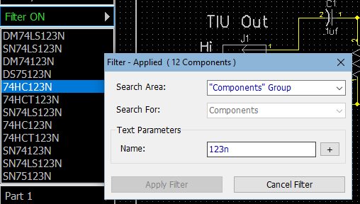
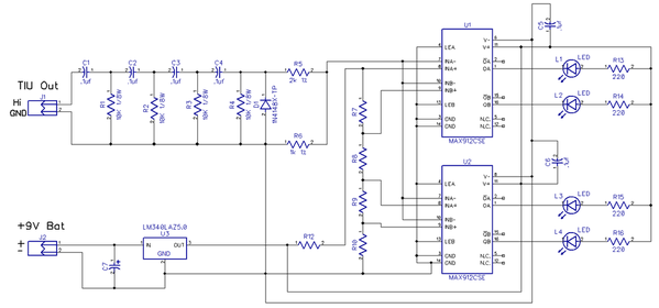
You searched for SN74HC123N, there isn't that specific part.  However, if you leave off the "SN", you do get a couple hits.

In the case I stated, I searched for 123N, that yields 12 parts.  Note the SN prefix was only on the xxLS123N parts.

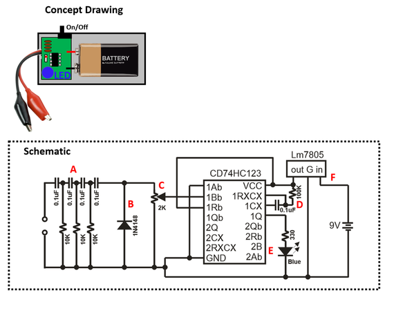
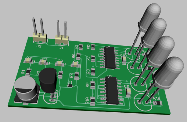
As far as the pot, I had a larger one of the same style in there, but when I looked for it, it wasn't stocked anywhere.  Oh, all the resistors are 1/4W, and the caps are all 50V or better.

Adrian didn't have pin numbers on his drawing, but I tumbled to the fact that he had the chip laid out like it physically appears, so pin 1 is the left top, then you count down and around and up the other side.  Given that "clue", I just used the hopefully correct pin numbers to match his design.

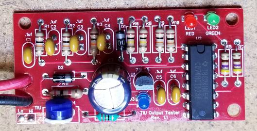
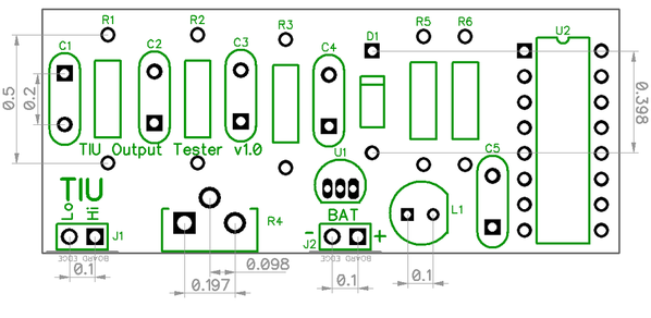
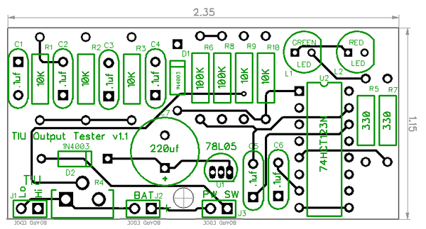
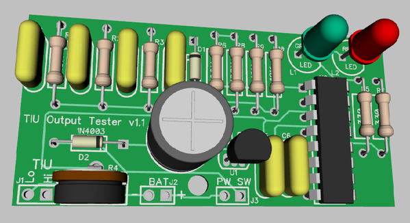
There was no specific plan to make this as small as possible, I just arranged the components in a square in a somewhat logical pattern based on the interconnections and then drew the board outline around them.  I didn't see any reason to squeeze it any further, if I really wanted to, it could probably be half an inch shorter.

As far as "customization", I do have my own set of libraries that I add parts to.  I try not to modify the stock DipTrace libraries so that upgrades are painless.  If I hack their libraries, I'd have to go back and do it again for updates.  However, it's easy to create user libraries.

Using OSH Park is dead simple!  You just create an account, and when you login, you're presented with a "start" page.  Drag-n-drop the Gerber ZIP file onto the page and follow your nose. 

For quantities of boards, you can also consider SEEED Studio, you can get ten boards for around the price of three on OSH Park.  SEEED does take longer, I'm still waiting on my order of PCB's for the TMCC Buffer surface mount version, ordered on June 23rd.  However, three of those from OSH Park would have been $43, and they were only $12.69 from SEEED Studio, so I went for the cheap option, I've already invested hundreds into the TMCC Buffer project with no returns yet, I can wait a couple extra weeks.

Attachments

Last edited by gunrunnerjohn

Thanks again GRJ! I really do appreciate all your help! I am starting to get the hang of things somewhat and the DipTrace files will really help here I think. If I live long enough I may even be able to make my own PCB!

I did do the 123N search and looked through all the possibilities there, but I guess I just missed a couple or got confused? Also, the labels didn't seem to match Adrain's labels? I guess that's where your experience comes in and I get mixed up. Probably shouldn't have been looking for an exact match on that part either. 

The PCB layout was really interesting how DipTrace laid it all out and then added all the wiring/traces. It's amazing how they program all this stuff to do that! I then fiddled with re-arranging a few things, but that still needs work on my part as well. I think one could make a PCB from the automated one created, but I wanted to try and optimize it like you do yours here on the forum. Fun to fiddle with that part! I haven't yet made it to the 3D part, but I bet that is pretty cool too.

I was looking at making my own library to make a chip 'exactly' like Adrian's, but I have not got that part mastered just yet. More study and trial and error needed here too! I think having your own library is something that would be a very good idea to have as you have done.

I did get the Gerbers posted and ordered at OshPark and that was pretty easy as you describe. The 'drag and drop' was really nice and it only took a few seconds for them to check the files and put them on order. They also take PayPal which I like and the total for the three PCBs was only $10.75 & free shipping, pretty reasonable I think. More amazing software stuff at work, they make it painless!

I would be happy to send payment for my TMCC buffer if it would help any. I know you must have quite a bit into that by now and that one is a lot of work too, I'm sure, and there are lots of them by now too. 

Anyway thanks again for all your help. I'll try not to be such a PITA as much as possible! 

I wouldn't bother to make a part to match his part, you'll have plenty of chances to practice making parts if you use DipTrace for anything else.

PCB schematic capture and layout has gotten a LOT easier over the years.  I used to do the PCB layout with tape, talk about a PITA, and changes were a nightmare!  Here's a page that describes the process, it was not pretty!  PCB Design, a Graphic Artist's Handicraft by Skilled Designers.  Checking the tape job was a very tedious task for large boards, and if you weren't REALLY careful with the taped mylars, you'd lose a trace or two.  You had to create all the top and bottom layers and have perfect registration between them.  Your best friend was the light table.

After you finally got the taped mylar design verified, you got films made.  You had a whole stack of films, one for each layer, both silkscreens, both solder masks (if different), all the copper layers (depending on the number of board layers, etc.  This whole bundle got shipped to the PCB house to actually create the boards.

...

Not to worry about the TMCC Buffer, as soon as I get the SMT boards in and test that layout, I'll be sending out the group email for everyone, then they'll have to commit with real cash to be in on the order.  This is a BTO process, and it'll be a one-time deal, I'm not planning on making the buffers a long term thing.  I'll be doing the board and assembly order from one of the Chinese houses I use, and I have to have a decent quantity to do a build at a reasonable price.  There are also several $10+ parts in the design that I'll have to source, as well as the plastic enclosure and power module.  I have everything figured out as far as production, and I've even built a simple assembly jig to drop the completed boards from China on to add the thru-hole parts with the proper spacing.

I suspect once the initial demand is satisfied, there'd be very few additional orders.  I never expected this to be a cash cow, I just made a commitment to Dale about doing the build.  Even though he's gone, I felt it was only right that his legacy be carried forward, he did the heavy lifting on the project.  Also, I'm sure that some people that get them will later decide they don't really need them, so there's bound to be a "used market" after a time.

That really looks like a terrible process to have to go through for a PCB! I would have never tried one doing it that way. The modern software and PCB makers have really streamlined the process from doing it the old-fashioned way. I briefly fiddled with DigiKey's KiCad but never got too far with it. I think DipTrace does seem to be easier than that one anyway.

I did a tiny bit of drafting in the late '80s (not electronic related) and it took a lot longer than today using a computer with good software. At the time the company had only one IBM PC/AT with Autocad so there were not enough to go around, It wasn't long until they got more PCs and everyone had their own. That was new and fun back then. I will say that I think the computer designing is much easier to make a mistake in, such as copy/paste and forgetting to change something that was a little different (I still do that!). I think in the manual drafting an error was much easier to spot and you had to draw each item so the copy/paste errors were non-existent. The PC was much faster though and also much easier to make revisions on. Time saved outweighed the occasional extra errors. We had nothing like Diptrace though, that is pretty impressive!

The Digikey first order of parts came today. I had absolutely no pots with the mount on the PCB so I ordered some of those and a few other items today. Should be here by Friday. Oshpark emailed that the PCBs will be on their July 20th PCB layouts (or something like that) and then go off to be made. Won't be too long now!

Ok on the TMCC buffer, I knew from your earlier posts that some of the parts were expensive (and so is moving, first-hand experience there a few years ago). That turned out to be a lot of work and I'm sure Dale would be pleased with it all coming together now and his work being carried on. 

I will probably be one of the people that doesn't actually need one, but thought I better get one while the getting was good. You can't have too many electronic gizmos! I do plan to expand my layout, that was the idea from the beginning, but things have not progressed much after I got the first part up and running. It's still in the plans, maybe I'll make it someday? 

To ALL:

If anyone is interested in ordering PCBs from Oshpark I can try to figure out how to share the project and post a link here for anyone that is interested. It was $10.75 for 3 boards with free shipping. For parts, I ordered extras for a discount price so I don't have an itemized cost breakdown per part to get a total cost per board. All parts I ordered are from DigiKey, they had everything.

Or you can wait and see how mine turn out and go from there. I will post my progress as I get the parts in and get things put together. Also, I think I got all the parts correct, but I usually goof something up somewhere so the material list may need a little adjustment?  If you want to wait I can make any corrections to that as well. It's GRJ's PCB design that I used, so I am sure that will be fine, probably no worries there.

Adrian! posted:

I just use Ansys SiWave and Altium for PCBs. Costy but good.

I'm sure that some of the professional PCB packages are great, but I don't have the budget for several thousand dollars for the schematic capture and PCB layout stuff.  The small boards I'm likely to do just don't justify that kind of expenditure.  For what I do, DipTrace works very well, and is considerably easier to use than Eagle, one of the other major players.

The last that I was exposed to printed circuit board design, it was very labor intensive, but I liked the old days of drawing things by hand.  I'm thinking of the late '70s to 1980.  Of course, It took time and each person's productivity was very low compared to today.  Since then, I have worked with already produced products.  Just as someone coming from a postwar train background and being exposed to command control trains, it seems like my background in PCB is from the stone age!  

Actually, I didn't like the "old days" when it comes to PCB design.   Doing all of that stuff by hand was very tedious, and I could visualize much better uses for my time.  Doing something simple like the little TIU Signal Tester by hand would take probably all day doing all the drafting by hand and then routing and taping the PCB design.  Next, you had to do the films, and finally get the package to the PCB house.  I was able to do that little task in about an hour, much better use of time.

I agree it's a much better use of time.  My preference is because I'm not the kind of engineer who can develop anything.  I think it is better that I have found a nitch as one who puts a circuit together using commercial building blocks, writhing work orders for the technicians, and documentation.  Those are all things most don't want to bother with.  Maybe I should have taken the position as a technical writer way back in '76.  It didn't seem interesting at the time, but finally that seems to be what I am good at.  

Jeepers Creepers, this is why Design Engineers need PRACTICAL Engineers to over see them  When I first brought this up, GRJ said it was too hard and too costly, so get an Oscilloscope.   NOW, Adrian designs what I asked for about $10, and all of a sudden GRJ is asking for upgrades for it!!!!

So let me add some practical advice.  Certainly a go no go is ok and I certainly would pay $40 for one that can easily test a TIU output.  Show a perfect signal around 12V with Green, Show and acceptable around 9V with Blue and a Red for no go.

If there is a crude adjustment POT that can be calibrated in rough voltages to get a green to light up at the set value 3, 6, 9, or 12 that would be great, and no other LED required.  Start at 12V, no go, set to 9 and retest, still no go, set to 6V and if it lights up, you have a rough estimate.  But frankly if less then about 9V from what I have been reading and you should replace the Transmit chip.  So a simple device and I do not see how Service techs would not pay $40 for the test equipment.  We far more for a PS-3 Test set.  BUT we need something that doesn't take up square yards on the work bench, so for me a O Scope is out.  This device is in.   Thank you for this effort.  ADRIAN if you build me one I will pay for it and then pass the charge on to MTH  G

George, that was my idea with the four LED's, but as pointed out, it's probably overkill.  However, you have a design that won't take up much room and will give you a quick indication if the TIU has a full strength output.

Truthfully, if I were going to spend more time on this, I'd probably try to eliminate the pot and have it trigger on something like 11 volts peak signals, any less and you'd get a no-go.

To anyone using GRJ's design as a starting point to learn the tool.  Here's a project.

Only 1/2 of the 123 chip is being used.  This means you can add a 2nd threshold and 2nd LED which might make the tool more useful.  So LED1 would blink when a full level packet (12V or whatever you guys come up with) is detected.  And LED2 would additionally blink if the packet is above, say, 50% of the full level.  The component cost would be pennies - LED plus a few resistors, caps.  Not as handy as having 4 thresholds but small steps.

With only one LED, if it doesn't blink it could alternatively mean that the battery is dead.    

Separately, if modifying the 1 LED design, I suggest terminating (e.g., tying to ground) the input pins on the unused half of the 123 chip.  It is not a good idea leave unused inputs "floating" (not connected to anything).


Stan, I was thinking that simply adding a resistor divider based on a 5V reference, you could have a second LED with no adjustment pot.  As long as you assume the +5V is within around 5%, it would probably be accurate enough, and it sure makes calibration a moot point.  Of course, adding another 123 would give you the four LED's I started with.  With a PCB, it would be pretty easy to add the extra components, no hand wiring involved.

I think I see feature creep rearing it's head!

hc high low input thresholds

So here we have what would happen in a typical engineering company back in the day.  An engineering design review subjects the schematic to the peanut gallery (other engineers) who weigh in and must "sign off" before PCB layout.

The problem with using the 123 is the thresholds are not calibrated.  This being in contrast to the comparator design showed earlier.  In principle the 123 chip is specified to trigger anywhere between 1.35V and 3.15V … a fairly wide range.  Within one chip, the two halves of the 123 will trigger at the same levels just from how the device is manufactured.  But the thresholds can vary between two chips.  This makes the 4 level detector (using two 123 chips) problematic and would probably not pass a design-review in a corporate environment.  But we're talking hobby DIY so I'll grin and bear it.  

Attachments

Images (1)
  • hc high low input thresholds
stan2004 posted:

hc high low input thresholds

So here we have what would happen in a typical engineering company back in the day.  An engineering design review subjects the schematic to the peanut gallery (other engineers) who weigh in and must "sign off" before PCB layout.

The problem with using the 123 is the thresholds are not calibrated.  This being in contrast to the comparator design showed earlier.  In principle the 123 chip is specified to trigger anywhere between 1.35V and 3.15V … a fairly wide range.  Within one chip, the two halves of the 123 will trigger at the same levels just from how the device is manufactured.  But the thresholds can vary between two chips.  This makes the 4 level detector (using two 123 chips) problematic and would probably not pass a design-review in a corporate environment.  But we're talking hobby DIY so I'll grin and bear it.  

Exactly why I went with a trimpot instead of a fixed R-div

More good ideas! I was hoping Stan would be along with some suggestions.  

I will try doing this, but I do think 'feature creep mode' has been activated. Think I'll wait until this percolates a bit more? 

My draftsman left a resistor off of my schematic...just wait 'til I find him! Good thing I used GRJ's to order the first round of PCBs. 

(Looks like it has been 'creeping' while I was writing!)

Last edited by rtr12

Other participants in a typical corporate design-review would be someone from Marketing and someone from Manuals.  It's maybe just my experience but these guys were usually silent (or maybe asleep?) but in this case might suggest that you need a way to turn the widget on and off - and if using a 2-pin non-polarized connector, what happens if you plug in the battery backwards?

9v battery connector holder

Here are two 9V battery-holder connectors suitable for PCB use.  The connectors themselves "guarantee" correct polarity on a 9V battery.  I suppose the on-off "switch" could be the act of inserting the battery.  Otherwise, the right example right shows a cheap (10 cent) on-off slide switch.

Attachments

Images (1)
  • 9v battery connector holder
Last edited by stan2004
Adrian! posted:

$400 - Real Oscilloscope 

$90 - USB Oscilloscope like the T-train

$40 - GRJ with 4 LEDs with fixed Rs and comparators

$10 - Adrian with 1 LED and trimpot tuning

I think the market is pretty much flooded at this point?

Agreed.  Just suggesting that if the journey is to learn DipTrace and the process of fabricating PCB's via OshPark, it's always useful to bring something to the party given GRJ has already done the heavy-lifting on the $10 version.  So this would be, say, 

$11 - Adrian with 2 LED and trimpot tuning

I figured out the issue with the trigger of the 123 after I posted it, which made sense why Adrian has the pot.  So, to use more 123's, you'd need more pots, that would be ugly!  I guess the comparator is probably the way to go if you wanted to have multiple LED's.

I thought of a power switch and also maybe an input cap and diode so you could run this on AC or DC and from a plug-in power supply.

Last edited by gunrunnerjohn

I don't have an "official" list of parts as most of them are all very generic parts.  All the resistors are 1/4w thru-hole resistors, the caps are all 50V ceramic.  The 74HC123N is the standard thru-hole 16 pin part, any maker is fine.  The LED is just a standard 5mm or 3mm LED in the color of your choice.  The regulator is the LM340LAZ-5.0 or similar three terminal 100ma regulator.  The pot is the only "special" item, it's the Bourns 3306W-1-202.

GRJ, what is the lead-spacing of the caps?  It looks like 0.25" or 0.3"?  I realize it's just a place-holder but the 3-D rendering shows a radial package which tend to be expensive and harder to find with such large lead spacing.

cap package

Point being if you go to DigiKey and search for 0.1uF 50V ceramic capacitor,  you are overwhelmed with choices.  While terminal wires can be manipulated to fit in whatever hole spacing, I think some guys would rather just be given a specific part number to use.

So another participant in a corporate Design-Review process was a representative from Purchasing who, rather than being asleep, was always chomping at the bit to nail down exact part numbers for good reason.

To that end, note that Adrian in his early post suggests he used the HCT version of the 123 chip:

http://www.newark.com/texas-in...ip16-5-5v/dp/25M8579

The HCT version has a lower threshold trigger voltage than the HC version.  It probably doesn't make a difference in this application if using a trimmer to tune the voltage, but if you're after apples-to-apples, the DigiKey version would be:

https://www.digikey.com/produc.../296-2088-5-ND/38252

If anyone is putting together an "official" DigiKey parts list, 

the 1N4148 diode could be:

https://www.digikey.com/produc...8/1N4148FS-ND/458603

 DO-35_1N4148_sml

And the least expensive flying-lead 9V battery-holder appears to be:

https://www.digikey.com/produc...232/36-232-ND/303804

232,3,4_sml

1/4W 10K resistor could be:

https://www.digikey.com/produc...4JT10K0CT-ND/1830374

CF%2010k

Other resistor values also available in the CF14.... "family" of 1/4W resistors at same price (4 cents each at qty 10).

330 ohms

https://www.digikey.com/produc...4JT330RCT-ND/1830338

100K ohms

https://www.digikey.com/produc...4JT100KCT-ND/1830399


Attachments

Images (4)
  • 232,3,4_sml
  • DO-35_1N4148_sml
  • cap package
  • CF%2010k
Last edited by stan2004

Good points Stan.  I actually did miss that Adrian suggested the HCT part, good idea.

In looking at the HCT part, it's current outputs are pretty low, maybe a larger resistor on that LED...

Lead spacing for the resistors is .5"

Lead spacing for the caps is .2"

Lead spacing for the diode is .4"

Here's the board with what should be all the dimensions you might need, including the connectors, the pot, etc.

Attachments

Images (2)
  • mceclip0
  • mceclip0
Last edited by gunrunnerjohn
Mark Boyce posted:

Yes John, that is what I thought.  I’ll review and order tomorrow.  It has been a very interesting and informative discussion!!  Many thanks to Adrian, John, Stan, George, and RTR

I certainly agree Mark! A big thanks to all the designers (RTR not included )!

I'm making the go-no-go one as well, but may do some more fiddling with some of the other suggestions above. The parts I ordered were just about the same as what Stan posted so I think I got that part ok. We will see when the boards get here.

Last edited by rtr12
rtr12 posted:
Mark Boyce posted:

Yes John, that is what I thought.  I’ll review and order tomorrow.  It has been a very interesting and informative discussion!!  Many thanks to Adrian, John, Stan, George, and RTR

I certainly agree Mark! A big thanks to all the designers (RTR not included )!

I'm making the go-no-go one as well, but may do some more fiddling with some of the other suggestions above. The parts I ordered were just about the same as what Stan posted so I think I got that part ok. We will see when the boards get here.

You are the user who asks the important questions to get the designers to give more detail on the points they took for granted, so to speak.  This is coming from the documentation guy who writes the first step; "Plug power cord into 120v AC outlet"  


gunrunnerjohn posted:

...

In looking at the HCT part, it's current outputs are pretty low, maybe a larger resistor on that LED...

Well now we're entering the eyes-glazing-over zone, but the 330 resistor is no problem in this application.  The 4 mA output current characteristic for the 74HC and 74HCT family is simply a point on a curve.

74hc output load line

For example, with a 5V chip supply voltage, the output pin driving the LED can supply 10 mA if you don't mind the output voltage dropping to 4.4V.  Or you can get 20 mA if only 3.7V is suitable.  There are considerations and equations that get messy when you push the envelope but for this application 330 ohm resistor is not asking for anything untoward.


Attachments

Images (1)
  • 74hc output load line
rtr12 posted:
...

I'm making the go-no-go one as well, but may do some more fiddling with some of the other suggestions above. The parts I ordered were just about the same as what Stan posted so I think I got that part ok. We will see when the boards get here.

So as part of the learning moment are you considering modifying the schematic and the actual PCB layout?

If so, I will describe my 2nd LED idea which would "cost" you 4 resistors, 1 capacitor, and the additional LED...but using existing values so no "new" values to procure.  

Last edited by stan2004

Stan, if you have a "second LED" idea that's functional, I'd be glad to add it to the existing design.  The good thing is that I haven't ordered any of the boards yet.

stan2004 posted:

 Well now we're entering the eyes-glazing-over zone, but the 330 resistor is no problem in this application.  The 4 mA output current characteristic for the 74HC and 74HCT family is simply a point on a curve,

 I guess I should have actually downloaded the data sheet, I just saw that on the Digikey site and it caught my eye.

Last edited by gunrunnerjohn

Well, I realize this is a situation where size matters since you pay OSH Park by the sq. inch.  The additional cost for components is 25 cents or so.

TIU%2520Signal%2520Tester%2520v1.0%2520Schematic modified for 2nd led

Add a 10k-10k divider that generates a 2nd trigger signal that is 1/2 the amplitude of the original trigger.  Add a 100K-0.1uF combo to set the blink pulse duration of the 2nd timer.  Add a resistor-LED for the 2nd LED.

The idea is as follows.  You have two trigger voltages, one being 1/2 of the other.  The 123 chip will trigger when the voltage at the "B" input is about 2.5V.  We'll call this the full-scale trigger for a good TIU output.  The other trigger would then be about double that or 5V which of course will trigger the other half of the 123.  

But if the TIU level drops, the lower trigger will fall 2.4V, 2.3V, 2.2V, etc. while the higher trigger will fall to 4.8V, 4.6V, 4.4V, etc.  So in this case only one LED will blink.

So rather than a go, no-go the creeping feature syndrome makes this a go , maybe, no-go. 

Attachments

Images (1)
  • TIU%2520Signal%2520Tester%2520v1.0%2520Schematic modified for 2nd led
Last edited by stan2004

And from the peanut-gallery, if the Gerbers are still pending, how about a hole to make a strain-relief loop for the battery holder wires.  I'm not clear if you're advocating the 2-pin male-female connector (looks non-polarized which is iffy IMO) as the on-off mechanism.  But if running the red-black battery connector wires soldered right to the pads (no connectors), looping the wires thru a hole is a cheap "free" strain-relief to prevent the wires from breaking at the solder joints.

peanut gallery pot shot 1

Attachments

Images (1)
  • peanut gallery pot shot 1

Looks doable Stan, I'll work something up.  I actually order stuff like this from SEEED Studio if I want a few, ten boards of any reasonable size are around $12.70 shipped, and it takes about a month to get them.  I just got my TIU Buffer boards for the surface mount version back, and I ordered them just about a month ago.  The restrictions are they are 1/16" DS boards, no options, and quantity 10.  However, they're two sided boards with silk screen and solder mask both sides, so they're nice boards.

OSH Park is great for little modules, but once the boards get more than about 1 sq/in, I look for other options.  I like the little boards from OSH Park as I can get them in 1/32" and with heavier copper so I can run narrower traces and still have decent current capability.

I can get boards like this from China about $40 for 100 pieces if I want a lot of them.

Stan,

Yes, I was planning to do some more fiddling and would be happy to add your ideas, but GRJ will probably have it done and posted by the time I finish writing this...  GRJ's design will probably be more compact and 'correct' as well. 

I plan to still fiddle with the Diptrace program some more as well, so willing to try anything at least once or twice! Unlike GRJ, I will probably need the full board review (with revisions) prior to boards and parts or Gerbers.  

Sorry, I have been busy with Dr's appts and a dental implant the last half of this week and haven't gotten much of anything else done. Good news is cardiologist scheduled me back again in one year. I'm taking that as a good health report! May even have time to finish a Diptrace drawing... 

rtr12 posted:

Stan,

Yes, I was planning to do some more fiddling and would be happy to add your ideas, but GRJ will probably have it done and posted by the time I finish writing this...  GRJ's design will probably be more compact and 'correct' as well.

I'm fast, but not that fast.   However, I think this is fast enough.  

Here's the "Stan0004" upgrade version.

  • Two level detection and indication.
  • Strain relief for battery connection.
  • Provision for external power switch.
  • Cap and diode to allow power from AC or DC sources.

Needless to say, the PCB got larger since this is an all thru-hole design, currently 1.15" x 2.35".  I thought about making it for 1/8W resistors except for the LED's, but decided to stick with what I have using the 1/4W parts.

TIU Signal Tester Rev. 1.1 Gerber.zip

TIU Signal Tester Rev. 1.1 3D View

TIU Signal Tester Rev. 1.1 Schematic

Attachments

Thanks, GRJ, that was plenty fast!  I was just fiddling with Stan's adds to the schematic, but not finished just yet.  Now I can see how I did for correctness. I hadn't thought of the diode and cap on the supply, probably would have thought of that unless you or Stan said something. Some added learning for me for next time. 

Glad you stayed with the 1/4W resistors, I have lots of those, 1/8W not too many (if any?). 

OSH Park says the PCB order has gone to the board maker, shouldn't be long now for Rev 1.0. Maybe sometime next week? 

Also, thanks Mark! 

RJR, if my parts are all correct and fit the PCBs I ordered, I will 'Share' the PCBs on OSH park and post a link here. I can also make a detailed parts list of what I ordered. I was hesitant to do that until I see if it all fits together and works correctly with my ordered parts. And also there were still discussions of added features going on with the first PCBs.

Then I will try the Rev. 1.1 project and do the same for it. 

Only thing I didn't order was the jumper for the power switch, I have a ton of those already, from years of fiddling with computers.

I guess I can go ahead and share the 1.0 boards now, I will just mark them Rev 1.0. I'll do that later today and report back.

I've been watching sense day one of the thread. This would indeed be a handy little devise if one has any doubt as to weather any of there channels is having an issue in regards to signal strength. I was all set to build Adrian's original version with GRJ's first OSH zip file but thought I'd wait in hopes the other electrical gizmo gurus would jump in a crank this thing up a couple of notches. Low and behold, BAM!

A kit would be nice. However, a zip file and a parts list would work for me thank you very much.

Last edited by milwrd
RJR posted:

GRJ, are you going to make anything available as a kit, like some of your earlier excellent kits?

I hadn't considered it, I was considering maybe just ordering a bunch of the blank boards and putting together a BOM for Digikey for all the parts so it would be easy for someone to build them. 

OSH Park wants $13.70 for an order of three of the 1.1 boards, so they're more than $4/ea.  I can get them for less than a buck if I order 100.  Of course, I have to be able to recoup my money for boards, so offering kits is always somewhat risky.

GRJ, I assume that if you made boards available and a BOM, that you'd be including a schematic so us neophytes could see where to place the components, and that it would be thru-hole so we needn't have surface mount skills???

RTR, I understand from my son just south of you that cold weather has struck your area---that it's below 90.  :-}

Obviously, there would be a schematic.   I could also actually put the component values right on the silkscreen of any production board, that's sometimes useful for hand built stuff.  This is all thru-hole construction, there are no significant size restraints, and all the components are "full sized".

What would be slick is a nice little box for it so it was a "finished" unit.

As for the weather, we had great weather for quite a stretch, in the 80's, low humidity, no rain, etc.  Now it's turning wet.

Last edited by gunrunnerjohn

Yes, it was only 89 so far today! Been way too hot this year. Maybe even some low 80s later in the week too, finally!

As for the boards and parts, I will defer to GRJ on all that unless he wants me to do something.

I'll wait on GRJ for the OK to share them on OSH Park too, he did do all the heavy lifting as Stan said above. And GRJ, I agree that project box would be a nice touch for these.

If you're game for some minor mods:

TIU board

Without increasing board size, I think you could add 1/8" mounting holes in diagonal corners as shown.  This would take #4 screws.  I like to mount tiny boards like this on a piece of acrylic so the nothing shorts out on the bottom of the board.  Example:

mounting holes handy

I'm not sure what everyone's plan is for connecting the TIU input wires, but perhaps a strain-relief hole is needed for those two wires too.

I think the components in the upper left can be moved down to make room for the mounting hole.  I note that your 3-D cap body looks much larger than the actual 0.2" lead-spacing component...where the leads are actually bent out to make them wider.  Point being there is more room available than the component outline suggests.

It looks like the 3-D rendering of the LEDs shows the flat-side on the left while the silkscreen shows the flat side on the right.  Trivial but for whatever reason caught my eye right away!

I'm not sure on what the call the 2 LEDs (weak, good, whatever).  But note that for a "good" signal, both L1 and L2 should blink.  For a "weak" signal, only L1 will blink.  The trigger voltage to the #1 half of the 123 chip gets the larger trigger voltage.  The schematic calls L1 "good" and L2 "weak".  

Attachments

Images (2)
  • TIU board
  • mounting holes handy

Good input, I stuck the "weak" and "good" in at the last minute, I'll have to go back and fix that.

Here's the "latest".   Let's see how close this is.

I added holes all over the place, changed the caps to .1 spacing as those are more common, not to mention smaller footprint.  Of course, I did change the LED colors, you were right.  I figure the power switch might just be a .1" jumper pair with a jumper on them, that's the simplest case.

TIU Signal Tester Rev. 1.1 Gerber.zip

Edited 7/22/18 at 22:00 to insert latest files and graphics.

TIU Signal Tester Rev. 1.1 3D ViewTIU Signal Tester Rev. 1.1 PCBTIU Signal Tester Rev. 1.1 Schematic

Attachments

Last edited by gunrunnerjohn

I have just been watching and holding off for now.

I still want to say thanks to all involved in developing this for their work.

I like to see things move forward and eliminate any guesswork. I am a big MTH fan and have met and heard from people who are not.

I have been blessed overall with well performing DCS equipment. I don't believe I put it under extra undo stress! I always thought 2 rail would have worse shorts then 3 rail would. Just something I stumbled on and kept in the back of my mind. Probably is not correct but was something I heard in the wind....

I'll try these at OSH Park again. If you are going to go with the kits, I will just leave the OSH Park ones un-shared. If you don't want to do the kits, let me know and I will share them if you want so others will have them available. 

If you do the kits I will order one myself, just to compare parts, boards, etc. to see if I am close. I think there will be some takers for the kits.

Thanks again for all the design work! I am still fiddling with Diptrace, but I have a long way to go before mine looks anything like yours does!

Thanks to all, Adrain, GRJ, Stan, and everyone else!  


GRJ, I like your jumper switch too, Diptrace and Digikey were not cooperating at all with me on a slide switch. 

Last edited by rtr12

I thought about a slide switch, but then I figured that was another unique part that I might not be able to find.

I'll probably use SEEED Studio to get ten boards as they'll be as cheap as three from OSH Park.  I'd like to actually build one of these and make sure it works as expected before I turn it loose on the public.

If you share stuff on OSH Park, you really need documentation as well as the boards.  Stuff like the BOM, schematic, assembly notes, etc.  Otherwise, it's not very useful for folks that find it there.

I'm still not happy with the LED situation.  

led

Per the schematic, the 2 cathodes (pin 1) are connected together.  For virtually all LEDs, the flat-side of the body is the cathode.  On the PCB drawing, the square-pads (presumably pin 1) are indeed connected together... yet the flat side of the LED silkscreen is on the right side? 

As for the on-off "switch" presumably you are assuming someone is using a 1-cent shunt to install on the 2-pin header.  I'm sure there are many variants but you can also get 2-pin switches that have similarly narrow profiles in the same footprint.  

on off

Next thing you know the peanut gallery will be demanding an LED to indicate power is on!  


Attachments

Images (2)
  • led
  • on off

GRJ, I will just wait on the sharing. If someone wants one from OSH Park it is very easy to order there with your posted Gerber files. Then there is the Documentation, probably not something I could explain? If you go with the kits that will be a much better setup for those wanting one anyway (that part probably also being slightly over my head, then there is the docs thing again). I'll stick with the Diptrace struggle for now. 

Stan, I have a bin full of those jumpers for the on/off headers, but I do like those little switches.  Not sure I have seen those before? I may just go have a look for some. Maybe I can finally one up Diptrace here (since GRJ already has the pins selected)...I have extra LEDs as well, just in case the need arises! 

Stan, that's the pattern that they have for a 5mm LED in DipTrace, I'll check and see if they're backwards.  If so, I'll make my own pattern with the correct footprint.   I actually rotated the 3D part to match the silkscreen, I guess that may be a mistake!

I never saw that switch before, that drops right into the spot for the jumper!   Where did you see those?  Got a source?

Believe it or not, I thought of a power LED, but since this was battery powered, I decided that was overkill.

Attachments

Images (1)
  • mceclip0
Last edited by gunrunnerjohn

OK, found the issue I think.  They have both flavors in the library for LED's, don't know why they have a reversed image one, but I changed them for "standard" LED's.  I'm going to update the build files "again", but I'd wait a day or two before actually using them in case we find something else.

Link to post with current files: TIU SIgnal Tester Rev. 1.1 Build Files.

No source for that switch - one of those parts in the stash that I've had since the last century.  I'd think it would be easy to find but then again, Nothing is so easy as the job you imagine someone else doing.

Regarding the power LED:  the LM340 standby (quiescent) current is about 3 mA typical...so a 9V battery would only last a few days if left "on" inadvertently.  While a power LED would also draw a few mA, presumably it might catch one's attention at the end of the day reminding to turn it off and save the battery.  A tradeoff for sure.  Of course if track-powered using your optional power method, the LED power is not an issue.  Matters of this significance are above my pay grade. 


Stan, I looked around for a switch like that, and I'll be darned if I can find anything like it.  It's a slick idea, too bad it's not obvious how to find it again!

A power LED with a big resistor might make sense, make it only draw a mil or two, you don't have to have them smokin' hot to indicate power.

How about the S-812C50AY-B2-U regulator, 500na quiescent power.  Only 16V input voltage, but it sure doesn't waste power.   99 cents at Digikey.

I suspect it is nowhere as popular as a slide switch with 0.1" lead spacing such as - about a dime in modest quantity:

spdt slide

I suppose you could whack off the 3rd pin for use as a basic 2-pin OFF-ON SPST switch assuming there's space for the body.  The somewhat annoying aspect of the previous 2-pin switch is you must lift the actuator to turn off.  It is not spring-loaded for push-on-push-off action.

After some web searching, I found it interesting that hobby and Robotics related sites "get it" and sell these switches (and only a few other types) making a point of the 0.1" lead spacing - perfect for DIY prototyping boards with the 0.1" grid hole pattern.  You go to DigiKey and hunt around forever trying to narrow down the thousands of choices.  

Attachments

Images (1)
  • spdt slide
gunrunnerjohn posted:

...

A power LED with a big resistor might make sense, make it only draw a mil or two, you don't have to have them smokin' hot to indicate power.

How about the S-812C50AY-B2-U regulator, 500na quiescent power.  Only 16V input voltage, but it sure doesn't waste power.   99 cents at Digikey.

Not sure about the 16V limit.  I figure in this specific application some guys might hook the tester to AC track voltage which of course would be 18V command-voltage since this is for TIU testing!

If it were up to me (which it is not!), I would forego the AC option (9V battery only)…and use the real-estate and cost savings from the large electrolytic and diode for an on/off slide-switch and a resistor and power LED (1 mA).

Here's the latest build.  I updated the previous post with all the build files, link below.  This adds Stan's power switch and the 1ma power indicator, it's the blue LED.  I also shrunk the LED's to 3mm LED's no reason to make them king sized for such a small board.

I think we have reached critical mass, if I want to put more on it, I suspect it's time to to to 1/8W resistors.

TIU Signal Tester Rev. 1.1 3D View

Link to post with current build files: TIU Signal Tester Rev. 1.1 Build Files

Attachments

Images (1)
  • TIU Signal Tester Rev. 1.1 3D View

George, it's only for testing the TIU, not for permanent connection.  The one downside of this design approach is due to the parts used (cheap was a primary goal), you have to calibrate each unit using the pot on the board.  That being the case, I'll probably just calibrate mine using my 'scope for around 11 volts P-T-P for the "good" signal.  The "bad" signal ends up being approx. 50% of the amplitude of the "good" signal, in this case around 5.5 volts P-T-P.  If you have a known good TIU, you can simply use the good channel as a standard and calibrate so that the good channel indicates a good signal.  In my mind the "bad" signal is primarily to tell you that the TIU is putting out some signal, but appears to have a weak channel.  I envision the unit to be calibrated to really require the "good" signal to consider the TIU channel to be fully functional.

The usage is to simply power up the TIU, and connect voltage to the input of the channel being tested, and the tester to the output of the channel.  Power up the tester and check the lights, job done.

I'll be generating a BOM for the parts in the near future, so many projects, so little time.

Regarding the AC-power version.  I realize this measures the DCS amplitude with no load on the TIU output except the tester itself (or an oscilloscope).  That said, since the tester is such a minimal load, is there any chance it can be powered by the TIU output itself?

That would make for a simple 2-wire connection.  I'm imagining the temptation will be great to see how the LEDs blink at various points on a large layout (no trains, just the track).  Not clear where you'd get the AC power in such a situation.  But then, ironically, the tester would need a 22uH choke!  


Last edited by stan2004

I suppose, since you are having to power the TIU channel to initially generate the DCS signal that you could just connect the power to the DCS output.  As you say, adding a choke would be the only requirement.

That thought never occurred to me, but it seems it should work.  In that case, you wouldn't need the power switch or the extra set of pins for the power.  It appears that just adding a choke to the input and sending the TIU channel 60hz through the existing rectifier and filter would be all that's required.  Since you're powering the channel, you have gobs of 60hz power available, no need to worry about what you're using.

TIU Signal Tester Rev. 1.1 [self powered)

Attachments

Images (2)
  • mceclip0
  • TIU Signal Tester Rev. 1.1 (self powered)
Last edited by gunrunnerjohn
gunrunnerjohn posted:

Here's the latest build.  I updated the previous post with all the build files, link below.  This adds Stan's power switch and the 1ma power indicator, it's the blue LED.  I also shrunk the LED's to 3mm LED's no reason to make them king sized for such a small board.

I think we have reached critical mass, if I want to put more on it, I suspect it's time to to to 1/8W resistors.

TIU Signal Tester Rev. 1.1 3D View

Link to post with current build files: TIU Signal Tester Rev. 1.1 Build Files

I think I know where the post is with the latest design files, but I could also have lost my way?   Now the 'New Linky No Worky' at least not for me.    However, if the link goes to the last post with an upgrade, which I think it does, I think I got it!  

You guys go way too fast for me, by the time I partially figure out the latest changes you are at least a board design or two ahead of me.

Any chance you guys could type a bit slower... 

I agree, they move too fast for me.  That is good!!!  I’m just waiting until the dust settles, or as John said the feature creep runs itself out!

Carry on men,  I’m glad to see progress.  The place I am spending what I think will be the last months of a career in electronics isn’t like this.  Everyone talks about doing things, but progress moves at a snail’s pace!  LOL

Sit tight for a few days, the landscape is changing.   I like the self-powered idea, glad Stan thought of that.  I don't see how it should affect the DCS signal in any way, and it really simplifies the usage of the tester.  I'm still looking at it an making "tweaks".  For one, it occurred to me that the .5" spacing for a 1/4w resistor was generous, they fit just fine in .4" spacing, so I adjusted the layout to accommodate them.  This makes it easier to fit stuff on.

Here's a shot of what I have right now, the LED's are now 3mm units, and the resistors and diodes are all .4" spacing.  It's not quite so crowded now, though the board is getting full.  Thru-hole stuff takes a lot more real estate than surface mount, this would be on a board half this size or less.

I kept the board at the same size as before so far.

Attachments

Images (2)
  • mceclip2
  • mceclip3
Last edited by gunrunnerjohn

Steve, you're trying to do a lot more than this was designed to do.  This tester was a simple answer to the question of testing the signal strength out of the TIU channels as there are faults that reduce the signal strength from an individual channel while still producing some DCS signal.  You're really looking for a much more sophisticated solution to measure exact signal strength.  A multitude of factors influence the track signal available on the track at various locations.

I have such a device, it's called an oscilloscope.   This tool is not intended to replace such a device.

Image result for atten oscilloscope ads1102cal

Mark, I agree, I do like the 'feature creeps' proceeding quickly! I just get lost easily.   I guess I will join you in awaiting the dust making it's way to where ever it's going...Then try to catch up. 

We are in good hands with the designers at work here!

GRJ, maybe a dumb idea here, but would you consider leaving Gerbers posted for the other designs as they have progressed? Might be neat to have a variety of designs for folks to choose from?

Not suggesting they would all be supported, and one could not expect a kit of any model they chose. For use only if someone wants one of the other designs...of course they would be on their own to create it from what has been posted. I'm certainly not wanting to create a problem for anyone with this suggestion. 

Actually, I don't keep copies of old versions unless they're a useful version.  In this case, I didn't keep any.  I'm actually going to try and experiment and see if I can get more boards for less money from SEEED.  I'm putting three copies on one panel and if I get ten panels, I'll get 30 boards when I cut them apart.  The only slight oddity is when I duplicate the design, I get different component ID's, but that's not really that significant.  Here's an example of what I mean.  I'll simply cut along the white lines to make three boards.

Attachments

Images (1)
  • mceclip0

Ok, just thought it might be neat to have different designs. I have the first and maybe second or third and that is all, think I have two different files anyway. I have the originals still at OSHPark, boards are being fabbed now. Will be neat to compare the different versions, at least for me anyway. 

Three boards on one makes it cheaper I guess? I have gotten some ebay stuff that came as multiple boards that had to be separated for use after getting them. Must also be easier to assemble that way at the PCB builders/assemblers, I guess? Makes sense to do in quantity. Will be interesting to see the price differences too, I bet.

For SEEED Studio, they make ten boards for a fixed price, and they don't go by size.  I suspect if I sent them a huge board it would be different, but I got ten of my TMCC Buffer Boards for around $13, the composite size is very similar to three of these.  That being the case, I'd have thirty of these for around $13, not a bad price.

All of my stuff gets panelized at the PCB house, when I get them they're in panels.  It greatly increased productivity of the placement of parts as they don't have to do as many board changes to run production.  Mine are small runs, for really large runs, the boards can be 18" on a side, they're huge!

Here's a few examples of my stuff when I get it.

Super Chuffers

LED Lighting Regulators

Chuff Generators

mceclip1

Attachments

Images (3)
  • mceclip0
  • mceclip1
  • mceclip2

Hi John: Three questions.....    DCS-TIU Port Tester Tool

(1)  Can this test be done on the layout, clip the alligator clips to the track? 

(2)  What information will I receive by doing this test, and how will I apply this information?

(3) I used to like to built Heathkit projects, they are a Michigan Company and they are still in business but not like their golden days.  My first project was a single channel transmitter and receiver for a RC Airplanes.  (1968) • I even did the color TV with a friend in the 70's.

With this being said:  If you can put this project into bag, with the directions and all the parts, I would be interested in building  this new item? If you have plans to do this I would purchase this kit. Is this part of the big plan?  (Right Price)

Gary

Mark Boyce posted:

This up to date PCB planning and buying is an education in and of itself.

Absolutely!  I am curious how the boards are cut apart for the first 2 units shown.  The Chuff Generator seems easier since it has nice gaps between the boards, but the first 2 look pretty well packed with components that would be a high risk of damage when separating.  (I assume there is some specialized tool made to do exactly this and I just don't have a clue what it looks like)

-Dave

trainroomgary posted:

Hi John: Three questions.....    DCS-TIU Port Tester Tool

(1)  Can this test be done on the layout, clip the alligator clips to the track? 

(2)  What information will I receive by doing this test, and how will I apply this information?

(3) I used to like to built Heathkit projects, they are a Michigan Company and they are still in business but not like their golden days.  My first project was a single channel transmitter and receiver for a RC Airplanes.  (1968) • I even did the color TV with a friend in the 70's.

With this being said:  If you can put this project into bag, with the directions and all the parts, I would be interested in building  this new item? If you have plans to do this I would purchase this kit. Is this part of the big plan?  (Right Price)

Gary

Gary, this is really a tool to test the TIU channel without a layout in the mix.  It would take a more sophisticated tool to actually test with the layout and wiring in the picture as well.

You just get a go/no-go indication as to the channel's signal strength.  If you get only the red light, the channel is weak, if you get both, the channel is normal.  If you get neither, either there's no DCS signal or you have something connected and/or configured wrong.

Currently, I'm not planning on a kit, though I may make the PCB available for a good price.  Shipping will probably cost as much as the board, or more.

Dave45681 posted:
Mark Boyce posted:

This up to date PCB planning and buying is an education in and of itself.

Absolutely!  I am curious how the boards are cut apart for the first 2 units shown.  The Chuff Generator seems easier since it has nice gaps between the boards, but the first 2 look pretty well packed with components that would be a high risk of damage when separating.  (I assume there is some specialized tool made to do exactly this and I just don't have a clue what it looks like)

-Dave

Dave, the boards are V-Scored to make separation possible.  You just break them apart at the separation line.

GRJ, that SEEED pricing is quite good! I'd have to go back and look but I think you posted that one of the later PCB designs at OSHPark was $13 and something for 3. That is a big reduction, 30 PCBs for $13.   I doubt that I will ever be needing that many, but it's good to know anyway.

The Asian ones I got were about the size of your lighting boards in the pic above. I think it was the small DC-DC regulators. I can see where combining the PCBs like that would make things much easier to create and populate. 

Soldering iron is sitting in it's stand idling and ready to go! Now, I just have to figure out how to set them up after making them...I think Adrian or maybe it was you posted something earlier about that. Maybe a thread re-read is in order soon. 

The setup is pretty simple, you have one adjustment.  I'll be doing mine with a signal generator and a 'scope.  However, failing that equipment, connect to a good TIU channel all set up to get,and then "tune" the pot to turn on both lights.  You'll probably want a "tiny" bit more toward the lights on to compensate for small variations in the outputs, but not enough to let a bad TIU pass as good.

I was hoping to hear from Adrian and Stan on the "final" version to see if we've missed anything before I go to press on a bunch of PCB's.

Thanks, I think I can handle that. I have one TIU channel (Var 2) that has never been used, so that should be a good one, I hope.

I imagine Adrian and Stan will be along before too long. It's always good to have them (as Stan described the process above) look at things before production. I have noticed it's really difficult to get something past Stan! (He must get up really early! ) Also, I really like all your cooperative design projects, very interesting and informative to follow along with. Especially for a rookie greenhorn like me!

rtr12 posted:

GRJ, that SEEED pricing is quite good! I'd have to go back and look but I think you posted that one of the later PCB designs at OSHPark was $13 and something for 3. That is a big reduction, 30 PCBs for $13.   I doubt that I will ever be needing that many, but it's good to know anyway.

Well, it wasn't quite that good a deal.   Turns out, they take exception to multiple designs on one panel, so I couldn't do my trick of having three on one "board".  Also, since ten of these boards exceed the maximum first class shipping weight, the freight is more as well.

Still a lot better deal than the $13 for three of them.

Attachments

Images (1)
  • mceclip0

The latest incarnation hasn't wandered too far from Adrian's original design.  As I look at the latest schematic I believe you can even implement his exact original circuit by selectively populating the board with the original parts.  The modified version does add a half-dozen or so line-items but it still looks to me like $10 or so in parts.

Some of the components are needed in quantity 1 whereas even at DigiKey you can save quite a bit per unit by going to quantity 10.

MFG_PRT-12978_sml

Adrian shows a red-black pair of alligator-clips to attach to the TIU output jacks.  Obviously they don't have to be red and black, but try finding "just" 2 alligator-clips leads.  Or maybe everyone already has these clips lying around.  At DigiKey it looks like you buy a set of 10 double-ended cables for about $3... of which you only need half of a red and half of a black.

https://www.digikey.com/produc...1568-1582-ND/7056460

My guess is most guys would prefer a built-and-tested version...rather than firing-up the soldering iron, ordering DigiKey components, ordering bare circuit board(s) from OSH Park / SEEED, etc..   I might have missed it in the conversation but has anyone stepped up to providing completed units...or if not then at least a kit of parts?  


Attachments

Images (1)
  • MFG_PRT-12978_sml
Last edited by stan2004

Are you suggesting alligator clips just to keep the cost lower?

Since the TIU has banana jacks built in, and this project is intended to just test at the TIU itself, I'd be inclined to put banana plugs on the end intended to mate to the TIU posts.  Just the plugs seem to be about a buck a piece.  Using a pre made test lead would raise the cost of the project significantly though, I guess (well, maybe $5 per lead - not expensive, but double the $10 we started with )

-Dave

Last edited by Dave45681
stan2004 posted:
My guess is most guys would prefer a built-and-tested version...rather than firing-up the soldering iron, ordering DigiKey components, ordering bare circuit board(s) from OSH Park / SEEED, etc..   I might have missed it in the conversation but has anyone stepped up to providing completed units...or if not then at least a kit of parts? 

You're right, most of the folks probably do want a completed unit.  That was my experience with several other projects, I started them out to be kits, and almost everyone wanted assembled and tested.  I may consider doing a kit of parts, but I'm not willing this time to have to put it together.  Perhaps we can recruit someone else to build them.   They're fairly easy as they're all thru-hole.

I'll probably buy ten sets of parts for the ten boards I'm getting.  Actually, I really only need the HCT123's, and the 2K pot, I think I have all the resistors, caps, and diodes in quantity anyway.  I know I have a ton of 22uh chokes left over from a quantity buy for another project.  LED's?  Tons of them.

FWIW, I agree with the dual banana plug, or at least individual banana plugs.  No sense in using alligator clips, they're not nearly as easy to use.  Now that it's just one connection to the TIU channel, it'll be a quick PnP test setup. 

I think the alligator clip leads are cheaper than a couple of good banana plugs by themselves. I think Stan's linked set of alligator clips are less than a pair of the banana plugs I have been using, which are heavy duty and fit tightly in the jacks. They don't loosen up like many of them do these days.

I have alligator jumpers, and was originally thinking of just cutting a red/black pair in half as Stan says above. The banana plugs sound like a good idea too (hadn't thought of that) and I also have plenty of those on hand.  

GRJ, let me see how I do on mine? If all goes well, I might consider building some if there are not too many orders for them. I like the kit idea myself, but my direction writing would probably be a major disaster. They would all be throwing shoes at me!

Maybe a small quantity of assembled units and a kit option would work? Hopefully more kits than assemblies.  

Last edited by rtr12
gunrunnerjohn posted:

Track power MUST be provided to the channel under test or it won't generate the DCS signal.  If you're seeing the DCS signal on a TIU output, that channel is powered.

Actually if you have voltage on the aux power in, and no channel power the packet still comes out... I figured this out like a day ago.

gunrunnerjohn posted:
stan2004 posted:
My guess is most guys would prefer a built-and-tested version...rather than firing-up the soldering iron, ordering DigiKey components, ordering bare circuit board(s) from OSH Park / SEEED, etc..   I might have missed it in the conversation but has anyone stepped up to providing completed units...or if not then at least a kit of parts? 

You're right, most of the folks probably do want a completed unit.  That was my experience with several other projects, I started them out to be kits, and almost everyone wanted assembled and tested.  I may consider doing a kit of parts, but I'm not willing this time to have to put it together.  Perhaps we can recruit someone else to build them.   They're fairly easy as they're all thru-hole.

I'll probably buy ten sets of parts for the ten boards I'm getting.  Actually, I really only need the HCT123's, and the 2K pot, I think I have all the resistors, caps, and diodes in quantity anyway.  I know I have a ton of 22uh chokes left over from a quantity buy for another project.  LED's?  Tons of them.

FWIW, I agree with the dual banana plug, or at least individual banana plugs.  No sense in using alligator clips, they're not nearly as easy to use.  Now that it's just one connection to the TIU channel, it'll be a quick PnP test setup. 

Ive updated the title of the forum thread accordingly based on all the design progress...

gunrunnerjohn posted:

The thing about alligator clips is the small one Stan illustrates don't clip will the the posts on the TIU.  I have a bunch of similar ones, and they don't work well with that style of post, they keep popping off.

Well, for less than $1 shipped (from Asia) you can choose your poison!    This pair has bananas on one side and alligators on the other.

alligator conundrum

I have no problems making a firm, solid contact using the alligator style to the TIU jacks.  Additionally, though not the intended application, you can easily attach alligators to the track which would be quite the hat-trick with banana plugs.  

The key is the strain-relief hole to loop the red/black wires thru so that the soldered-wire connections don't fatigue/fail over time.

And if you don't mind waiting for shipping from Asia, what appears to be the same set of 10 double-ended alligator cables is available for about 1/2 the price on eBay.


Attachments

Images (1)
  • alligator conundrum
Adrian! posted:
gunrunnerjohn posted:

Track power MUST be provided to the channel under test or it won't generate the DCS signal.  If you're seeing the DCS signal on a TIU output, that channel is powered.

Actually if you have voltage on the aux power in, and no channel power the packet still comes out... I figured this out like a day ago.

Isn't that the definition of passive mode?

Chris Lord posted:
Adrian! posted:
gunrunnerjohn posted:

Track power MUST be provided to the channel under test or it won't generate the DCS signal.  If you're seeing the DCS signal on a TIU output, that channel is powered.

Actually if you have voltage on the aux power in, and no channel power the packet still comes out... I figured this out like a day ago.

Isn't that the definition of passive mode?

Sort of.  The channel will output a WD signal only when power is first applied to a channel, and not again until a power cycle on that channel.  Truthfully, I never checked to see if the signal was coming out with just aux power, but it's an interesting tidbit.

FWIW, the tester should work exactly the same, connect to the port and you'll see a signal.  The filter allows the DCS signal to pass, so it's pretty much transparent whether there is 60hz to filter or not.

Obviously banana jacks can't connect to the track.   Considering the discussion that resulted when that topic came up a few times earlier in the thread, I considered that a benefit rather than a hindrance. 

If one can't easily attach the probes to the track, one is less likely to try to use it that way and then wonder why the results aren't what's expected.

I used regular Digikey prices when suggesting what the jacks would add.  I didn't try to go to eBay for direct from Asia pricing or anything like that.

-Dave

Last edited by Dave45681

John:

Like many others, I have been watching this thread and enjoying the discussion.  Please count me in for a kit, bare board, completed unit or whatever you decide to make available.  Setup for testing of DCS signal output on customer TIU's has been time consuming and inconvenient.

Thanks to all the electronics gurus for all the time you put in here.

The long wait is over, I finally got the 10 boards from SEEED Studio.

Here's the tester after I put it together, one small glitch in the layout, I got the pot backwards.  Didn't have one to look at and thought the legs went the other way.  Still works, you just have to adjust it from across the board.

I connected it to a TIU and fired it up.  It calibrated just fine, so I think it's probably doing it's intended purpose.  I have to do some more testing with various signal levels to see how it reacts, but it seems to function as expected.  I didn't have the 330 ohm resistors for the LED's, but it's perfectly happy with 470 ohm resistors.  The large leads go to the TIU, the board is powered through the TIU, so that's the only connection required.

Attachments

Images (2)
  • mceclip0
  • mceclip1

Slow down guys.  

My contribution to this effort was to lay out the board and build a prototype for testing.  I don't have the time right now with all my other projects to actually produce these.  However, I will make the board layout files, schematic, and BOM available when I get them all gathered up in a coherent form.  I'll also make the DIPTRACE files available in case anyone wants to "improve" the design.   You can work on this board with the free version of DIPTRACE, so no cost to tinker.  All the parts are commonly available, so there should be no issue in putting these together.

Perhaps someone else would like to pick up the baton and build some of these?

I like the red boards, yours looks neat and works. Much more colorful too!

I got my order from OSHPark, the v1.0 boards, assembled one of them and so far no worky? I haven't tried to see what's wrong yet, but upon examination nothing appears to be out of place? Or maybe my TIU is not performing properly, but I have only tried one channel so far.

I did manage to goof up my capacitor order, I got some funny looking tantalums instead of the ceramic I thought I had selected? Oh well, I still have 2 more boards to play with and I do have some ceramic caps around here somewhere. 

I still want one of your current versions though, and I'll be watching for the updated Diptrace files to order from.

Thanks again for doing all this GRJ, it's really a big help for us (me anyway) still trying to learn! 


Edit: If I figure out how to make one work and then am able to test them somehow, I would be willing to try and make a few for some of the other forum members.

Last edited by rtr12

Here are the design files for the TIU Signal Tester.  Included are the Gerber files for PCB fabrication, the Diptrace files to tinker with the design, and the BOM for ordering parts.  There are several other ZIP files in the overall ZIP file, the Diptrace files and the Gerber files are all separated out.  I did flip the pot around in this design as it was backwards in my original boards.

TIU Signal Tester Design Files.zip

You don't have to use the exact parts I used, they're all sourced at Digikey.  Most of the parts are very generic, and for any kind of quantity, you can probably find cheap eBay parts.  However, the BOM does give you industry standard parts and specs so you know what to look for.  Even sourcing them from Digikey, they'd be pretty cheap.  Stuff like the 2K pot will probably want to be the exact part as it fits the PCB footprint.  Have fun!

Attachments

Last edited by gunrunnerjohn

Add Reply

Post
The DCS Forum is sponsored by

OGR Publishing, Inc., 1310 Eastside Centre Ct, Suite 6, Mountain Home, AR 72653
800-980-OGRR (6477)
www.ogaugerr.com

×
×
×
×
Link copied to your clipboard.
×
×