
Take wecx800 as the example - this Schnabel is HUUUGE and Heavy - how is it that the couplers don't stretch and break under those intense pressures?


found this history so im not sure if the same technology is still being used. train guys ??


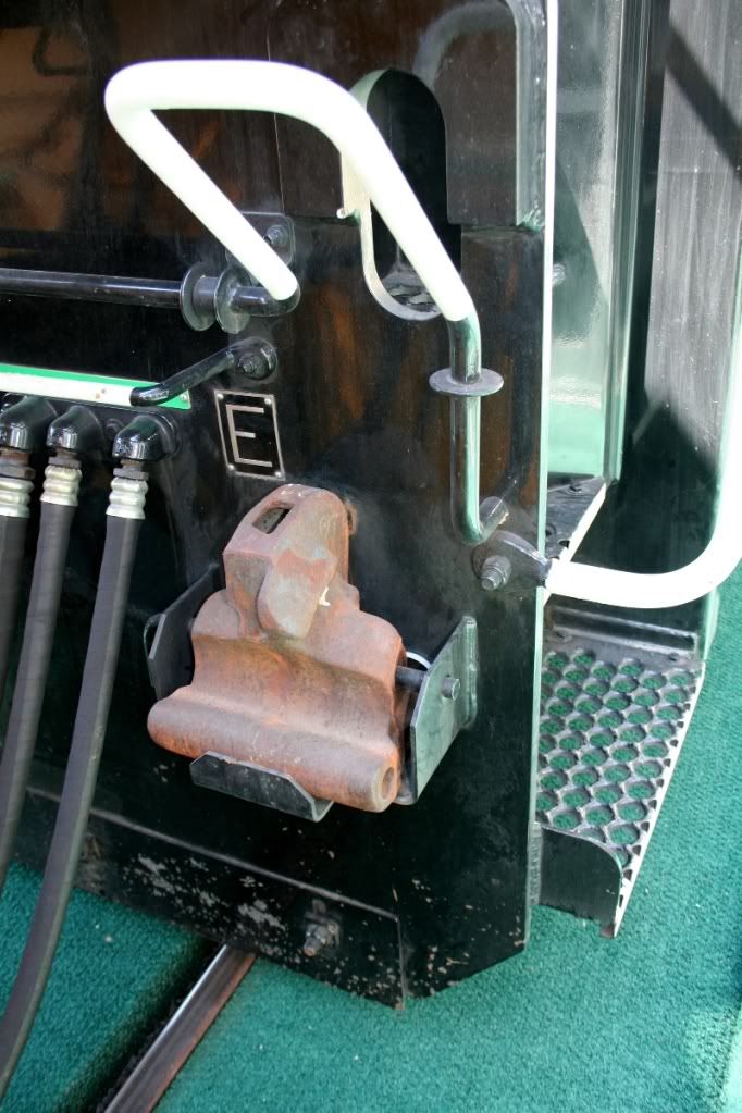
"In 1879, Eli Janney, a shop clerk and skilled whittler, patented his first coupler design. He whittled a wooden model of his "knuckle" coupler and commissioned a draftsman to make a drawing of it for his patent application. With a few subsequent revisions, Janney's coupler, which resembles two hands with fingertips hooked together, solved more than the safety problem. The Janney coupler automatically engaged without the need for a man to stand between the cars. It held train cars without slack, enabling smoother acceleration and more efficiency around curves, but with enough play to secure the train over hills. It also functioned as a buffer, preventing damage to passengers and cargo."


janney

Attachments

Images (1)
  • janney
Original Post

Replies sorted oldest to newest

Originally Posted by OGR Webmaster:

I seem to recall that a coupler could withstand somewhere around 240,000 pounds of pulling force. The weak point was usually the knuckle itself.


That is one reason why railroads have limits on how many powered axles can be on the head end of a train.

so the pulling force must be strongest at startup , after the cars are in motion it must decrease significantly I assume?

Posted by WestinghouseEMDdemoguy:
Originally Posted by OGR Webmaster:

I seem to recall that a coupler could withstand somewhere around 240,000 pounds of pulling force. The weak point was usually the knuckle itself.


That is one reason why railroads have limits on how many powered axles can be on the head end of a train.

so the pulling force must be strongest at startup , after the cars are in motion it must decrease significantly I assume?

That's probably true however in motion slack can "out do" the strongest engine pulling forces.   Hopefully the knuckle  breaks before  the draw bar gets yanked out of the end of car.


The knuckle pin  really doesn't do much except it  keeps the knuckle from falling out on the ground when the operating lever I  sused. I've had a few surprises  when using the uncoupling  lever, thankfully the knuckle didn't land on my foot.

I'm not sure about all the components, but most if not all are manganese steel. I used to re-build draft gear for SD 40's and 45's in the early nineties. There are more parts then one would think. The guy I replaced used to use CO2 fire extinguishers to try to freeze shrink the bushing at the rear of the main knuckle body. before trying to press the old sleeve out. I simply put the new sleeve on top of the old one, and as the old one pressed out, the new one replaced it. This was done with a hydraulic vertical press.

Another neat part was replacing the rubber shock pads in the part that fits in the draft gear pocket. I think the press was rated at 100 tons, but I'm not sure. I had to use oak spacers between the last plate and the cover plate to allow the assembly to fit into the pocket. After a bump during the first coupling, the shims would fracture, allowing the rubber to expand fully into the housing. I miss that place!

Don

The AAR car construction manual states that a freight car shall be designed for a sustained buff and draft load of 350,000 pounds.  Couplers are made from AAR M-201 steel.  Chemical composition for both grade C and E is the same, carbon, max. 0.32%, manganese, max. 1.85%.  Tensile strength, grade C, 90,000 psi min.; grade E, 120,000 psi min. Couplers are made to AAR M-211.  It requires static tension test (2.3.2.1.3) grade C knuckle, 300,000 lbs, and coupler 450,000 lbs; grade E knuckle, 400,000 lbs, and coupler 700,000 lbs.  I think the "HT" designation stands for "heat treat".

Originally Posted by Wyhog:

...a freight car shall be designed for a sustained buff and draft load of 350,000 pounds.

...Couplers are made to AAR M-211.  It requires static tension test... grade E knuckle, 400,000 lbs, and coupler 700,000 lbs.

I must not be understanding that right because it seems to me that a freight car built to withstand 350K lbs equipped with couplers tested to 700K lbs means the freight car would break in two at half the design strength of the couplers?

And I 've certainly never seen a coupler that could withstand anywhere near 700K lbs of pull?


So I must be interpreting the above figures incorrectly.

The freight car gets progressively stronger, with the knuckle being the weakest. The coupler is stronger than the knuckle, the yoke is stronger than the coupler, the draft lugs are stronger than the yoke, and the center sill is stronger than the draft lugs.  A modern center sill probably has a tensile strength of 1,000,000 lbs.  


The test values are for testing in a tensile test machine.  In the field there are shock loads and accelerations, so the actual loads to cause a failure will be somewhat lower than the qualification test loads.  When I was working for the railroad most couplers were grade C.  Grade E couplers were used on coal trains and on locomotives. 

I have also heard a similar explanation during a tour of a BNSF yard last year that the knuckles are the weakest. Apparently they are intentionally designed to have a lower strength so that they fail / break before the coupler or any other component in the freight car. Weighing significantly less than the coupler, the knuckles are also relatively easier to carry & replace by a crew member. to the extent I still remember the numbers, the knuckle weighed around 50 lbs which a crew member could carry but the coupler weighed 600 lbs. Most of the newer BNSF locomotives at the yard had 2 spare knuckles mounted on either side of the rear coupler. But I thought that the knuckles are not interchangeable between Type-F & Type-E couplers. Since BNSF has Type-F couplers on most of their newer locomotives & coal hoppers but Type-E (with shelfs) on all other freight cars, I am not sure what type couplers, the spare knuckles on the locomotives would fit.

These are just my opinion,

Thanks,

Naveen Rajan

 
Originally Posted by David Johnston:
Originally Posted by Wyhog:

...a freight car shall be designed for a sustained buff and draft load of 350,000 pounds.

...Couplers are made to AAR M-211.  It requires static tension test... grade E knuckle, 400,000 lbs, and coupler 700,000 lbs.

I must not be understanding that right because it seems to me that a freight car built to withstand 350K lbs equipped with couplers tested to 700K lbs means the freight car would break in two at half the design strength of the couplers?

And I 've certainly never seen a coupler that could withstand anywhere near 700K lbs of pull?


So I must be interpreting the above figures incorrectly.

The freight car gets progressively stronger, with the knuckle being the weakest. The coupler is stronger than the knuckle, the yoke is stronger than the coupler, the draft lugs are stronger than the yoke, and the center sill is stronger than the draft lugs.  A modern center sill probably has a tensile strength of 1,000,000 lbs.  


The test values are for testing in a tensile test machine.  In the field there are shock loads and accelerations, so the actual loads to cause a failure will be somewhat lower than the qualification test loads.  When I was working for the railroad most couplers were grade C.  Grade E couplers were used on coal trains and on locomotives. 


We used a continuous drawbar pull limit of 360,000 lb. The knuckle is designed to be the weakest link and therefore is designed to break first.

There is a good reason why most of the later high HP AC traction locomotives each have two coupler knuckle pockets at about waist level on the rear of the end frame. In the steam days locomotives that carried spare knuckles usually had one on the water deck of the tender. If you had to use it, you climbed the tender and dropped it over the edge, so the location on a diesel "saves a step". Isn't progress great!!

Originally Posted by Hudson5432:

In the steam days locomotives that carried spare knuckles usually had one on the water deck of the tender. If you had to use it, you climbed the tender and dropped it over the edge, so the location on a diesel "saves a step". Isn't progress great!!

Oh yeah?

Looks to me like the smart thing to do was to carry them in the tool tray under the side of the tender. Now, that's using your head for something other than a hat rack! Who's going to lift the darn things up to the top of the tender?


Tender9

Attachments

Images (1)
  • Tender9
Last edited by Big Jim

Did anyone watch the video after the coupler description? It was about camber on flat cars in the first few minutes. Another interesting subject. I was responsible for cambering the SD 40 and 45 beds. Three inch thick steel, with about sixteen inch I beams along the sides. A lot of work to remove a one and one half inch sag, and restore the arc to one and one quarter inch above flat.

Don 


Thank you to all who contributed to this thread. 

I assume the failure is in tension.  Does a coupler ever fail in compression? 


Seems like a much lighter set-up.  Does the structure and coupler system of a Roadrailer train have the same coupler load capacity????

My father worked for the Pittsburgh and Shawmut RR, in the car shop.  On occasion he would talk about replacing a coupler. After several years he turned wheels.


Last edited by Mike CT
Originally Posted by Hudson5432:

Big Jim,

That is where it was on NYC on PT tenders. (Being water level, I suspect that NYC did not pull many knuckles, at least in passenger service...) There was no clearance on the side of a PT for a tool box. I do know that on some NKP engines the tool box was on the front deck. I assume that it held a spare knuckle.....

Once again, it wasn't very smart planning. As you can see below, there is plenty of room for knuckles to be mounted on the frame of the tender. Just like many locos of today, all that is needed is room for some brackets.

There is plenty of room near at least three corners of the tender where a tool box could have been recessed into the carbody, much like a stoker motor would have been.

And, there is plenty of room under that "Booty" to hold a tool box.

Hoisting knuckles up to the top of a tall tender like that and then dropping them off...not very safe at all!!!

Oh well, too late now. That horse is dead!


Last edited by Big Jim
Originally Posted by Mike CT:


Thank you to all who contributed to this thread. 

I assume the failure is in tension.  Does a coupler ever fail in compression? 


Seems like a much lighter set-up.  Does the structure and coupler system of a Roadrailer train have the same coupler load capacity????

My father worked for the Pittsburgh and Shawmut RR, in the car shop.  On occasion he would talk about replacing a coupler. After several years he turned wheels.


The situation is not as nice in compression.  Failurers usually do not start until the compressive forces get in the range of 800,000 to 1,000,000 pounds.  When pushed all the way in the coupler horn hits the striker, transferring the force in the coupler directly to the draft sill. At this point the coupler casting will crack, the striker will be bent, the rear draft lugs may get knocked off, the center sill (or entire car) may buckle, and the car may come off the track.  i do not know much about Roadrailers, but I think theor problem was they were so light they easily came off the track if in train forces got high.

I must say, I initially thought that RailRunner was that RoadRailer-alike that K-Line modeled, but this is something quite different.


Edit: (K-Line modeled something called the "RailMate").


The PDF in the literature linked above contains a mechanical drawing of their bogie detailed enough to scratchbuild a model from


(hint hint, elbow, elbow)


---PCJ

Last edited by RailRide
Originally Posted by David Johnston:
Originally Posted by Mike CT:


Thank you to all who contributed to this thread. 

I assume the failure is in tension.  Does a coupler ever fail in compression? 


Seems like a much lighter set-up.  Does the structure and coupler system of a Roadrailer train have the same coupler load capacity????

My father worked for the Pittsburgh and Shawmut RR, in the car shop.  On occasion he would talk about replacing a coupler. After several years he turned wheels.


The situation is not as nice in compression.  Failurers usually do not start until the compressive forces get in the range of 800,000 to 1,000,000 pounds.  When pushed all the way in the coupler horn hits the striker, transferring the force in the coupler directly to the draft sill. At this point the coupler casting will crack, the striker will be bent, the rear draft lugs may get knocked off, the center sill (or entire car) may buckle, and the car may come off the track.  i do not know much about Roadrailers, but I think theor problem was they were so light they easily came off the track if in train forces got high.

Roadrailers ran in their own dedicated trains or hitched to the back of regular freight trains. These were generally not equipped with rear couplers as they were not intended to be placed mid-train.


One exception was Amtrak, who used a coupler-equipped rear truck to facilitate adding/removing the Roadrailer consist at terminals without involving the head-end power.


Roadrailers were tested on the Northeast Corridor to address concerns that they could be blown off the track if passed by trains moving at typical NEC speeds in the opposite direction. Reportedly, they "barely jiggled". I don't recall seeing images/videos of them being in actual service there though.


---PCJ

My guess, and it is a guess, is that welding coupler knuckle brackets to the GSC tender bed casting would not be encouraged. And top of tender would certainly be much safer location to retrieve a coupler knuckle than hanging knuckle or a tool box under the back of the tender and between the rail gauge. There was a steam heat line there and also a tender splash guard on tenders equipped with water scoops.

Originally Posted by Hudson5432:

My guess, and it is a guess, is that welding coupler knuckle brackets to the GSC tender bed casting would not be encouraged. And top of tender would certainly be much safer location to retrieve a coupler knuckle than hanging knuckle or a tool box under the back of the tender and between the rail gauge. There was a steam heat line there and also a tender splash guard on tenders equipped with water scoops.

Agreed. Besides, those NYC "PT" series tenders were just that, i.e. Passenger Tenders, thus not much call for spare knuckles. The shop forces would have been the folks placing the spare knuckles and/or tools up on the water deck anyway, so that if and when a knuckle was needed, a road person (Brakeman or Fireman?) would simply have to lift it slightly or kick it over the side.

Seems like modern diesels have the most utilitarian knuckle storage device: a vertical pin with 2 knuckles, mounted on the frame, either front or side.

        Recall a marvelous tale by good old David P. Morgan wherein he and Phil Hastings followed an ore train on the Shamokin Branch of the Pennsy. About half way into the trip, the quadruple header (2 I1 2-10-0's on the front, 2 pushing!) encountered a heavy rain storm, proceeded to stall on a grade, and attempted to restart the train. Front and back only had whistles for communication and the pushers backed up for slack, when the front engines began pulling forward. As Morgan noted, "There's a limit to what even steel can take", and the train seperated, with a broken knuckle on a hopper, mid-train.

         Morgan commented that he was at a complete loss as to what to do. The front locomotive head-end brakeman was given the task of taking the knuckle off the front coupler of the lead I1, and walking it back to the center of the train. No easy task! Anyhow, the train got put back together eventually, and marched triumphantly up the grade, after a lot of furious slipping of drivers and the rear-most I1 slamming hard enough into the helper in front, so as to slosh water out of the tender!!

Last edited by mark s
Originally Posted by Hot Water:
Originally Posted by Hudson5432:

My guess, and it is a guess, is that welding coupler knuckle brackets to the GSC tender bed casting would not be encouraged. And top of tender would certainly be much safer location to retrieve a coupler knuckle than hanging knuckle or a tool box under the back of the tender and between the rail gauge. There was a steam heat line there and also a tender splash guard on tenders equipped with water scoops.

Agreed. Besides, those NYC "PT" series tenders were just that, i.e. Passenger Tenders, thus not much call for spare knuckles. The shop forces would have been the folks placing the spare knuckles and/or tools up on the water deck anyway, so that if and when a knuckle was needed, a road person (Brakeman or Fireman?) would simply have to lift it slightly or kick it over the side.

I'll agree about the passenger train would rarely need a knuckle, but, if you two guys think dropping a knuckle 16 feet to the ground is a safe practice then I'm glad I never had to work with you.

This is much safer, and, it could have been hung without having to be between the gauge of the rail.

Last edited by Big Jim

"it could have been hung...."

Oh yeah?

WHERE?

PT tenders did not have end plates like diesels do......

I never said it was a safe practice...I just told you where it was located......

Perhaps the NYC enginemen did not have a tendency to break knuckles...NYC was a SPEED railroad, not a tractive effort railroad.

Or perhaps they simply had better engineers.....

Add Reply

Post

OGR Publishing, Inc., 1310 Eastside Centre Ct, Suite 6, Mountain Home, AR 72653
800-980-OGRR (6477)
www.ogaugerr.com

×
×
×
×
Link copied to your clipboard.
×
×