This subject keeps comming up. I have about 5 pairs of Ross switches wired up to work from one controller. One of them has a 1008 connected to it. This is the story.
The "L" on the switch machine MUST connect to the "L" on the controller and to the "L" on the other switch machine!
The "R" on the switch machine MUST connect to the "R" on the controller and to the "R" on the other switch machine!
"AC" from each switch machine MUST go to the hot side of your switch power!
The "C" on the controller MUST connect to the common return of your switch power!
DO NOT change these connections for any reason!
Mount the switch machines on the switches so that they move the switch in the proper direction when activated. If you can't mount the switch machine properly then you can't run both switches off the same controller. With Ross switches this is usually no problem but it can become difficult with Gargraves switches as they usually have only one location for the switch machine. The switch machines must be wired this way or the lights will not work.
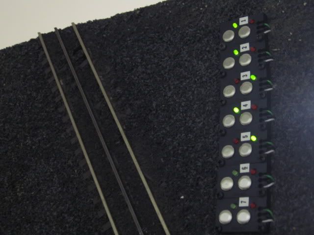
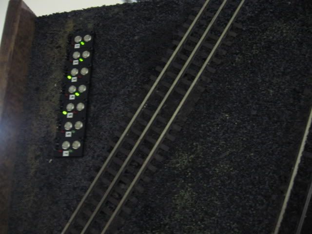
Now once you get the switches working it is finally time to get the proper lights to light. The Red and Green lights are interchangeable. Simply pull the light out and plug it in the other position. CAUTION! The lights are polarity sensitive. If you look carefully there is a flat spot on the side of the light and a flat spot on the side of the hole the light plugs into. These must line up. Please note: the flat spots on the switch machine are different from each other.
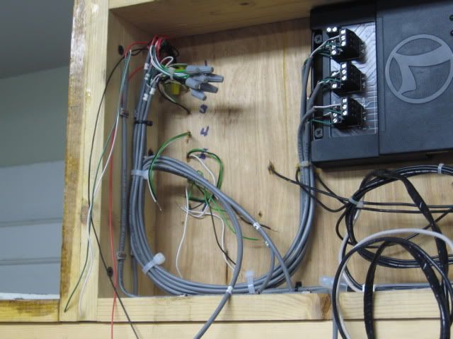
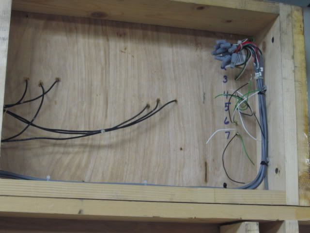
Now for the DZ-1008. Stop here if you do not have the switches working. Fix them first. You DO NOT need to piggy-back the 1008 to a switch machine. It can be just as easily mounted under the board or any where else. There are 7 wires comming out of the 1008. The Yellow wire MUST connect to the "L" terminal. This is the same as the little wire that sticks out of the 1008 and lines up with the "L" terminal on the switch machine.
The Green wire MUST connect to the "R" terminal. Again, this is the same as the little wire that sticks out of the 1008 and lines up with the "R" terminal on the switch machine.
The Red wire MUST connect to your switch machine hot power the same as the "AC" terminal on the switch machine. As with the other two this is the same as the center wire on the 1008.
The Black wire MUST connect to your switch machine power common return. This is the same connection you made to the "C" terminal of the switch controller.
The Blue, Gray, and White wires are your relay contacts. Connect these LAST and as necessary to get what you want. Please note, these contacts only have a 10 AMP rating. This may sound like a lot but if you use them to control track power, after a few shorts you could easily burn them out.


 Originally Posted by JoeTheBro: