The ERR RAILSOUNDS instruction manual does not recommend the use of rechargeable 9V batteries. Anybody know why? I have a bunch of rechargeable 9V Ni-MH batteries in stock. What would happen if I used one with the RAILSOUNDS board?
Replies sorted oldest to newest
Only reason is the RS board will not charge them. You would have to remove them to recharge them. Otherwise they will work like a non rechargable but not last as long.
Pete
ERR batteries/ BCR's require a separate power feed to charge. I've done a couple upgrades and they work fine.
Attachments
@Mossback Mike posted:The ERR RAILSOUNDS instruction manual does not recommend the use of rechargeable 9V batteries. Anybody know why? I have a bunch of rechargeable 9V Ni-MH batteries in stock. What would happen if I used one with the RAILSOUNDS board?
Why not go with a permanent battery that doesn't need a separate charging circuit.
@gunrunnerjohn posted:Why not go with a permanent battery that doesn't need a separate charging circuit.
Wow. That is expensive. It's too bad that ERR doesn't include it with the railsounds kit.
Unless you have a lot of places on your layout that have power gaps, you don’t really need a battery. Try running the train and see if you loose sound.
Pete
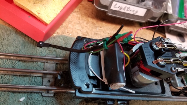
I finished installing the ERR Railsounds Commander in a Marx slope-back tender, and it is electrically tethered to a Marx 666 locomotive. This is the first time I've installed a Railsounds board - and it took me about 6 hours to complete the job.
Here is a video:
The Marx 666 is a noisy locomotive - lots of electrical noise and mechanical noise. The faster it goes, the noisier it gets. When it goes fast, all that racket almost drowns out the steam sounds. I have the volume turned all the way up - maybe I need to drill some more holes underneath the tender.
The ERR Railsounds Commander is supposed to have a bell and a horn - but using my old Lionel ZW transformer, I have no way to activate either the horn or the bell. However, the horn will blast once during the "battery-powered" shutdown audio sequence.
Attachments
@Mossback Mike posted:The ERR Railsounds Commander is supposed to have a bell and a horn - but using my old Lionel ZW transformer, I have no way to activate either the horn or the bell. However, the horn will blast once during the "battery-powered" shutdown audio sequence.
The whistle control on the ZW should activate the whistle on the ERR board. I'm guessing your ZW needs a new rectifier, perhaps the diode replacement would be a good investment for the whistle controls.
As for the bell, you can add an aux bell control box to control the bell.
You could also just build a whistle/bell control box and get both controls in one place. I cobbled this one together from junkbox parts years ago. It's actually had several homes, I gave it away twice. However, after the recipient upgraded their power to include the capability, they gave it back. ![]() It gives you both whistle & bell controls independent of the transformer controls.
It gives you both whistle & bell controls independent of the transformer controls.


Attachments
@gunrunnerjohn posted:The whistle control on the ZW should activate the whistle on the ERR board. I'm guessing your ZW needs a new rectifier, perhaps the diode replacement would be a good investment for the whistle controls.
As for the bell, you can add an aux bell control box to control the bell.
You could also just build a whistle/bell control box and get both controls in one place. I cobbled this one together from junkbox parts years ago. It's actually had several homes, I gave it away twice. However, after the recipient upgraded their power to include the capability, they gave it back.
It gives you both whistle & bell controls independent of the transformer controls.
Thanks John.
How would I make one of these?
My old ZW is doing some strange things:
With an old post war whistling tender, the ZW left-side controller works, but the right side side does not.
With my late 90s vintage MTH F3 with Protosound 1, not a single one of my post war transformers will activate the horn.
So far, none of my post war transformers seem capable of activating the horn on my new Railsounds-equipped tender. If anything, the loco has a tendency to speed up momentarily when I am pushing the whistle lever on my transformers.
Mike
@Mossback Mike posted:Thanks John.
How would I make one of these?
My old ZW is doing some strange things:
With an old post war whistling tender, the ZW left-side controller works, but the right side side does not.
With my late 90s vintage MTH F3 with Protosound 1, not a single one of my post war transformers will activate the horn.
So far, none of my post war transformers seem capable of activating the horn on my new Railsounds-equipped tender. If anything, the loco has a tendency to speed up momentarily when I am pushing the whistle lever on my transformers.
Mike
So postwar transformers like the ZW use copper oxide diodes- a form of metal diode semiconductor that utilizes a point contact system to the oxide layer. Take a 60Hz vibrating core- years of usage, thermal cycles, and so forth- nobody should be surprised to see a copper diode disk fail over time. The whole purpose of the diode is to be a check valve and pass current one way, not the other creating a DC offset in the AC waveform output. Copper oxide disk diodes are not very efficient and high losses meaning they are not great diodes when they did work, but served the purpose in our model train controls to activate the whistle relay of the time.
There are separate copper disk diodes in a ZW- one for each side, so it's entirely possible one failed.
Part2- some postwar transformers had compensation windings and circuits as part of the whistle control system to ADD voltage to the output to compensate since the air whistle motors draw additional current when operating- so basically in some transformers- when you activate whistle- there is a boost in voltage that expected to compensate for the whistle motor drawing current and slowing down. Modern trains use nowhere near the level of current or power and thus are likely to speed up since there is no massive corresponding current draw to offset the voltage rise.
Again- many folks remove the copper disk diodes in these postwar transformers and use modern silicon diodes that are much better and more stable rectifiers over time without the failures seen by the more mechanical stack nature of copper oxide disk diodes.
In a nutshell, your ZW may not be outputting a DC offset or enough DC offset to be sensed by modern trains and electronics.
Video on the ZW whistle diode replacement- https://www.youtube.com/watch?v=z9pzpz29gAc
https://ogrforum.ogaugerr.com/...w-whistle-diode-help
Another video https://www.youtube.com/watch?v=vCbYCtEcY6Q
EDIT: oops, I missed where John posted it above.
Great post by @gunrunnerjohn with a DIY Whistle/Horn and Bell box controller using modern diodes.
@Vernon Barry posted:So postwar transformers like the ZW use copper oxide diodes- a form of metal diode semiconductor that utilizes a point contact system to the oxide layer. Take a 60Hz vibrating core- years of usage, thermal cycles, and so forth- nobody should be surprised to see a copper diode disk fail over time. The whole purpose of the diode is to be a check valve and pass current one way, not the other creating a DC offset in the AC waveform output. Copper oxide disk diodes are not very efficient and high losses meaning they are not great diodes when they did work, but served the purpose in our model train controls to activate the whistle relay of the time.
There are separate copper disk diodes in a ZW- one for each side, so it's entirely possible one failed.
Part2- some postwar transformers had compensation windings and circuits as part of the whistle control system to ADD voltage to the output to compensate since the air whistle motors draw additional current when operating- so basically in some transformers- when you activate whistle- there is a boost in voltage that expected to compensate for the whistle motor drawing current and slowing down. Modern trains use nowhere near the level of current or power and thus are likely to speed up since there is no massive corresponding current draw to offset the voltage rise.
Again- many folks remove the copper disk diodes in these postwar transformers and use modern silicon diodes that are much better and more stable rectifiers over time without the failures seen by the more mechanical stack nature of copper oxide disk diodes.
In a nutshell, your ZW may not be outputting a DC offset or enough DC offset to be sensed by modern trains and electronics.
Video on the ZW whistle diode replacement- https://www.youtube.com/watch?v=z9pzpz29gAc
https://ogrforum.ogaugerr.com/...w-whistle-diode-help
Another video https://www.youtube.com/watch?v=vCbYCtEcY6Q
EDIT: oops, I missed where John posted it above.
Great post by @gunrunnerjohn with a DIY Whistle/Horn and Bell box controller using modern diodes.
Thanks Vernon - very informative. You just added to my "to-do" list.
Mike
A couple of thoughts Mike... replacing the mechanical E-unit in the loco with an electronic one would quiet some of the "buzz." And Lionel-style delrin or even die-cast trucks on the tender would probably be quieter than the stamped-steel ones used by Marx. Obviously we're getting further and further away from the basic mechanical ideal, but you already have an interesting hybrid on your hands. FWIW.
Love the mix of Marx and ERR; you might consider finding a CAB-1 or CAB-1L and Command Base, then go all the way to an ERR AC Commander in your 666.
Not free, but it opens up possibilities, as you know.


