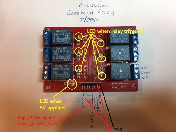
I am in need (desperate need) of advice on how to wire a relay switch.   A while ago I purchased some Geeetech 6 Channel relay switches to control 24 segments on my railroad.  I am wiring for DCS and conventional (mostly postwar engines).   I did not want to bring the heavy wires (14g) to the control panel but, instead, 20-24 g wires.  The relays, however, did not come with instructions and I cannot find any instructions on line that are either complete or that I can understand.  I am posting a picture of the relay and the description of the leads.  I have played with different combinations of wiring it but to no avail.  What I have done:

1) Brought in 5 vdc to the board via UCC and GND (Ground).  An LED on the board lit up indicating I had power to it. 

2) Inserted a power from transformer into NC (normally closed) and out to track via com - wired the common from the transformer directly to the track.  This approach did not work as the power was always on and not controlled via an On/Off Switch (later in discussion)

2) Switched the transformer power wires to NO and Com - still always on; and NO and NC which did nothing

3) Did not know how to put an On/Off switch into the wiring, I realize that Input 1 is part of it but where do I wire the ground?  I tried a common ground with the 5 vdc wires but that did not work. 

So, I am stuck.  Any advice would be greatly appreciated.  I am going to leave the same message in the electrical forum.  Thanks....

Mike

Geeetech 6-Channel Relay

Attachments

Images (1)
  • Geeetech 6-Channel Relay
Original Post

Replies sorted oldest to newest

You can try to add an on/off switch to connect GROUND to the input pin of the module. But that may not work because, in the off position, the input pin will not be connected to anything and will get neither GROUND (LOW) nor 5V (HIGH). It will be floating. Still, I would try it that way since when the unit is just powered with Vcc and Gnd, the relays are off. If not, you will need a different type of switch.

Professor Chaos posted:

Are you successfully switching the relays on and off?  You should be able to tell by listening for the click.

Your 5V DC power supply should be connected to VCC and GND.  These boards are active-low, meaning you activate the relays by switching GND from your DC supply to inputs 1-6.

Consolidated Leo posted:

Here is a wiki page that gives some basic information on the relay module. Active low is correct. The 5 volt power is also correct. NO is normally open, NC is normally closed, and COM is the common to both. When the relay is activated, COM connects to NO; when not actived, COM connects to NC. Activate the relay by connecting the input pin to GROUND.

How did you guys conclude these are "active low"?  As I read the wiki page, it suggests the inputs are active-high.

seems active low to me


Attachments

Images (1)
  • seems active low to me

If the board is "active-high" as I interpret the board description, then simply apply 5V to one or more inputs to trigger the corresponding relays.  According to description, in addition to a "master" LED that is on when 5V is applied, there is an LED for each relay that turns on when triggered in case your room is noisy and you can't hear the relay click.

Geeetech%25206-Channel%2520Relay

As suggested earlier, first get the relay board working...perhaps just using a piece of wire to apply 5V trigger to the input(s) to confirm the relays turn on and off.  Only then work on the control switch and track power connections.  My 2 cents.

Attachments

Images (1)
  • Geeetech%25206-Channel%2520Relay

This is what I would suggest for wiring your control panel switches. You'll need to use SPDT 3 pin 2 position on-on switches (toggle, rocker, slide, push button). On-off-on switches could also be used if you're so inclined.

As I said before, a standard SPST on-off switch might work if the relay module has pull-ups for when the inputs are not connected. There's no way to tell from the description if that is true. This wiring diagram ensures that the inputs always get either 5 volts or Ground.

mceclip0

The diagram only shows the first 2 switches. The rest would be setup in a similar fashion.

Until you figure out what polarity the input uses to activate a relay, I can't determine which way the switches should be labeled; one will be on and the other will be off. Test everything before you do the final installation.

Attachments

Images (1)
  • mceclip0

Thanks to everyone for responding.  I got it to work! Trying the different approaches suggested above, I switched around the wires coming from the 5v DC power supply and got it to trigger the 1st relay.  The wiring will be similar to the one posted above but I also want to incorporate LEDs to run to the diagram of the layout on my panel. Now onto wiring 24 circuits!  

Again, thanks everyone.

Add Reply

Post

OGR Publishing, Inc., 1310 Eastside Centre Ct, Suite 6, Mountain Home, AR 72653
800-980-OGRR (6477)
www.ogaugerr.com

×
×
×
×
Link copied to your clipboard.
×
×