
I recently got a Williams FA-1 which has two motors. I remember reading somewhere that you can connect the motors (in series?) so the engine will run slower.

I am looking for advice on how to do it. It is a 2009 engine with electronic reversing and horn.

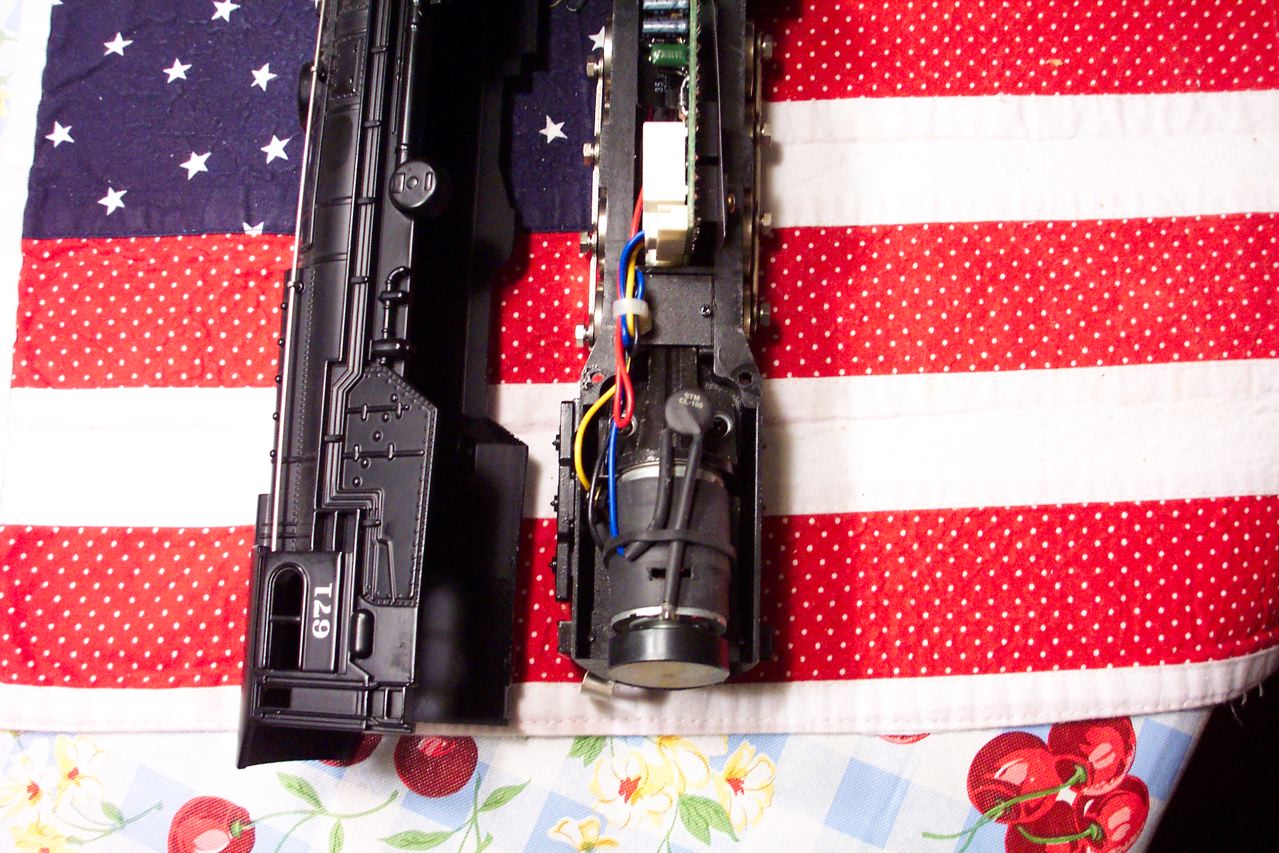
Is it as simple as removing the wire from the right terminal on #1 motor and removing the wire from the left terminal on #2 motor, and adding a wire to connect the two disconnnected terminals, thus in series?

Thank you for your comments.

Don
Original Post

Replies sorted oldest to newest

This is what I use. Its a type of thermistor called a current inrush limiter. Unlike diodes and resistors its a dynamic device that limits the startup current but not the top speed of the engine. Use one in series with each motor. The CL-150 linked above will work with the Mabuchi RS385 single motors used in virtually all current Williams products as well as Lionel Traditional engines. Use two CL 160's in dual motored engines
I might not be able to crawl at 1 MPH like a DCS engine but in slow race it would be pretty close.

Typical installation:


Pete
Last edited by Norton
quote:
current inrush limiter

Pete,
How does the current inrush limiter work after the engine has been running for a while, seems like it would work on initial start up then not do much until it has cooled off for awhile.

I guess wheat I am asking is, How long does it take to cool off to where it would slow the engine on startup again?
Justin, The resistance is an inverse function of current. The higher the current, the lower the resistance and the cooler the temperature. When you select these devices you want the maximum current rating of the device to be within 85-90% of the maximum that motor might draw under load. Most of these devices have near zero resistance at full current rating. From experience with their use in other devices I can tell you they run pretty cool. I tried a number of different models before settling on the CL150 and CL160s. They are fairly inexpensive though higher than I when I bought mine. Try playing with them.

Pete
Because wiring the motors in series has a sometimes undesirable side effect. The motors will exhibit a differential action... if one truck loses traction and slips, the other truck/motor stops. The stopped motor has resistance approaching zero, and the slipping motor gets twice the normal voltage, approximately doubling it's wheel speed.

This would be difficult to explain to buyers.

That said, later K-Line diesels had a DPDT switch on the bottom to switch between parallel & series.
The jack rabbit starts with Williams parallel wiring are the result of highly efficient can motors getting hit with the initial starting voltage of about 8 volts from "regular" Lionel 3 rail transformers such as ZW's, LW's, etc.

There's no jack rabbit problem with MTH or modern Lionel transformers because they are made to work with can motors and actually start at 0 volts and work their way up from there.

Fred
quote:
Originally posted by ricomon:
I understand that the diodes drop the voltage, but why not just use resistors?
Totally different beast. Resistors would dissipate a lot of power and the engine wouldn't go anywhere. Diodes have a fairly fixed voltage drop, around .8-.9 volts. A resistor's voltage drop would be dependent on the current flow.

Apples and oranges. Smile
That said, later K-Line diesels had a DPDT switch on the bottom to switch between parallel & series.[/QUOTE]

So, ADCX Rob, now I remember my manual for my K-Line MP15's and that it does
mention something about parallel vs series operation (MP-15) Diesel only. The note does say that if your "model railroading operation requires more realistic
speeds and slower starts, switch to "Series" operation.

Like I have written before...You Guys are Gooooooooood! You know your stuff, etc.


Rufus
Possible related problem with a Williams Scale GG1: Running it with a Z4000 I have NO problem with jack-rabbit starts. However, the horn won't sound until power is close to 7 volts. Speed is moderate to fast at 7 volts. So, essentially, I cannot sound the horn at slow speeds. Anyone else have this problem? Should I just make one of the modifications discussed here?
Thanks
For your horn issue, put diodes in series with each motor, that will allow the horn to get the power it needs, but lower the voltage to the motors several volts to give you the slow speed operation. You'll need diodes facing each way in parallel, each set of diodes will drop the voltage around 0.6-0.7 volts. I'd use 6A diodes, I'm pretty sure one motor won't tax those. You could probably use 3A diodes with no problem. Using 4 diodes in each direction, you'll drop the voltage around 2.5 volts to the motors.
Hi Don, I did a photo esay on how to wire Willaims motors in series. It shows the circuit board & plugs. Exactly how to do it. Very easy to do & it works good. The loco will still have very strong pulling power, that will not be an issue. Top speed will still be plenty fast. It just makes it slower.
The loco will run nice & slow for coupling up cars, the head light will be brighter & the horn will work better.
Print the photos. I think they will dissapear in a few days when site is updated.
Shown is my GG1, but I did it to all 5 of my dual motor locos. All mine have the same circuit board & wiring. Here is a link to the photo album:
http://ogaugerr.infopop.cc/eve...3102703/m/1212977327
Very best, Don Johnson
This may sound like a dumb question but did you look at the underside of the loco? Does it have a series/parallel switch? I have a Williams SW1500 that ran fast and realized that there is a switch on the bottom that allows me to change the connections. One flip and now it runs slowly. Is this the only model that Williams did that?
Sometimes folks complain of erratic horn operation on dual motor Williams. I found this when pulling light loads as well. They think it's the loco or transformer.
However the problem is too low a track voltage to trigger the horn properly. The rewire makes the loco need higher volts to run the same speed. That is why it cures the horn issues at low speeds or light loads. At the same time the headlight is brighter & looks better.
Very best, Don Johnson
quote:
Originally posted by og fan:
ATT: NORTON re; cl-150 are they polarity sensitive ? and should they be wired on the pos or neg side of each motor ? thanks


OG, Think of them as a variable resistor which they are. They are not polarity sensitive nor does it matter which motor terminal they are wired to.

BTW I just ran the Williams Turbine pictured above with a 135W Powermaster and I believe it will actually run slower than my Vision Hudson. The catch is, not having cruise, you have to adjust the speed slightly for changes in track surface. Maybe someday I'll master posting videos.

Andre and I are going to have to get together for a slow race. Big Grin

Pete
Last edited by Norton
quote:
I make this modification to all my Williams purchases. I wish Williams would just wire them this wa y from the git-go. They operate SO much better and still have plenty of power and speed.


Agreed! The first thing I do to a new Williams is wire the motor in series and take out the front and rear lights and install new Even's LED's. Big difference in operaition and apperence!
Hi Dominic, Remember the starting voltage of a loco is directly related to track load. Adding lighted passenger cars and/or pulling heavier trains will most certainly calm them down.
Each transformer has its own starting volts. Specifically the starting volts on a postwar ZW is about 8v. At 8v an unladened Williams diesel or electric pattern loco will run too fast to couple cars smoothly. It will slam the car way too hard. At the same time when pulling a light load with the throttle at it's very lowest setting, the train will be too fast.
You cannot start it smoothly when running light due to the start up voltage of the old ZWs is so high. As soon as you crack the throttle the slightest, it's off too fast.
That is what we're talking about.
The rewire fixes that.
Very best, Don Johnson
quote:
Originally posted by Chris Lonero:

Agreed! The first thing I do to a new Williams is wire the motor in series and take out the front and rear lights and install new Even's LED's. Big difference in operaition and apperence!


Ditto on the rewire.
I'm too lazy to search. Which Evan's LED's are you using in your Williams?

"Ditto on the rewire. I'm too lazy to search. Which Evan's LED's are you using in your Williams?"                                                                                                                                                                                                                                              I am using soft white 3mm "Generally" for the head lights and have just tried chip lights for the marker lights mounted behind the lens.

Hi Dave. I'm not sure what you mean by side receiver? I run conventional off of my TIU via the variable voltage port. The only thing I don't like is the voltage is in 5V. increments which means your starting voltage is 5V. which for some conventional engines is like a rocket ship taking off!  I would like to see MTH change this in the future and I would like even better is for Williams to put a switch in to give you the option of running in series.  

Originally Posted by superotrackdon:
Hi Dominic, Remember the starting voltage of a loco is directly related to track load. Adding lighted passenger cars and/or pulling heavier trains will most certainly calm them down.
Each transformer has its own starting volts. Specifically the starting volts on a postwar ZW is about 8v. At 8v an unladened Williams diesel or electric pattern loco will run too fast to couple cars smoothly. It will slam the car way too hard. At the same time when pulling a light load with the throttle at it's very lowest setting, the train will be too fast.
You cannot start it smoothly when running light due to the start up voltage of the old ZWs is so high. As soon as you crack the throttle the slightest, it's off too fast.
That is what we're talking about.
The rewire fixes that.
Very best, Don Johnson

What is odd is that we start the HTOS large portable layout at 8 V with W/WBB.  But we have several large zw's and other transformers on the layout at the same time.  My guess is there is a votage drop, so the "8" on the layout is a lot less,

Originally Posted by Fred Brenek:
The jack rabbit starts with Williams parallel wiring are the result of highly efficient can motors getting hit with the initial starting voltage of about 8 volts from "regular" Lionel 3 rail transformers such as ZW's, LW's, etc.

There's no jack rabbit problem with MTH or modern Lionel transformers because they are made to work with can motors and actually start at 0 volts and work their way up from there.

Fred

It's like using gasoline refined in the 1920's in a brand new car.

For my Williams locos, in addition to wiring the motors in series and replacing the headlights with LEDs, I also add some diodes in series with the motors to drop the voltage so that I have a higher starting voltage, and a lower "top end".  As a result, my lights and sound system come on while the loco has not started moving.  Then, as I add voltage the loco eventually starts moving, but the diesel rev sound also increases - a realistic effect. 


I am also installing one or two thermistors, so that the loco gradually increases in speed as the thermistors warm up.  I don't recall whose idea this was, but it was a poster on this forum. 


I just received my new Williams GP 30 with sound system.  Great runner and great sound, but it runs too fast for the diesel revs to change up from idle.  So, I will add the diodes and themistors to this loco as well, and probably replace the headlights with two small LEDs - we shall see.

I am adding diodes in ALL my Williams locomotives to reduce the high end engine speed. Adding diodes in series with each motor also allows me to have "directional" headlights. First I replace the regular Williams lamps with LED circuits.  Then By tapping off either the diode string I can wire to each headlight (LED) separately so that either the front or rear headlight is illuminated depending on the engine direction.


Note 1: I also use a Zener diode to provide constant headlight and marker intensity.


Note 2: Using another diode circuit I allow both headlights to be on (but dimmed) when the E-stop is set to neutral and power is applied to the engine. When the engine starts moving again the correct headlight is turned on (at full intensity) depending on the direction of the engine.

Series wired motors lower the high end speed but I believe adding series diodes to each motor is a better solution for reducing the high end speed.


Note: When motors are wired in series the motor current in each will be the same.  Wiring two motors in series does not guarantee that they each motor will run at the same speed since the efficiency of each motor may not be the same.

I have several Williams SD-45's, two sets of F-7's and a GP-9 and GP-38, that I use with either a Lionel post war ZW or an MTH Z-1000. I never had a problem with Jack-rabbit starts unless I did a stupid thing like leave the handle in the full open position and then turn on power to the ZW. Have been using my Williams for over six years this way, never rewired anything. I will admit the GP-9 is quick on the take off!

I picked up a transformer at a flea market that works great with my Williams GP-9, a Troller TAC 2001. The Troller  TAC has different voltage outputs; 0 to 9 volts and 0 to18 volts and has a whistle button. It was in a package deal for $20.00, 2 bridges, a couple of small buildings, and two used K-Line 042 switches.


Lee Fritz

Post

OGR Publishing, Inc., 1310 Eastside Centre Ct, Suite 6, Mountain Home, AR 72653
800-980-OGRR (6477)
www.ogaugerr.com

×
×
×
×
Link copied to your clipboard.
×
×