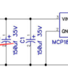
I have an interesting issue with a little regulator board.  I made this specifically to power fan motors on smoke units.  I did some bench tests with plain resistors checking out power handling, the supply performed just fine.

I connected a new MTH fan motor to it, it killed the regulator in a fraction of a second!  I thought it was a fluke, so I stuck a new regulator on and ZAP, it was gone in the same time!  OK, try a second motor with the third regulator... ZAP!

Lionel somehow manages to get away running the fan with a bog standard TO-92 LM78L05, but this regulator with more current capability and better heatsinking dies instantly!

Any ideas?  I'm at a loss what is happening.  I can't even get a good 'scope picture, it kills the regulator too fast!

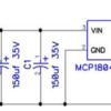
150ma Regulated Supply

Attachments

Images (1)
  • 150ma Regulated Supply
Original Post

Replies sorted oldest to newest

Looks like fun!

1. How much current does the motor draw?

2. Be sure the 1 uF on the output is good! I have posted elsewhere about the transients from motors wiping out LM317 regulators, and not in Lionel stuff! Maybe bypass the 1uF with a .01 or a TVSS. That is my strongest suspicion.

3. Be sure the motor is not grounded to the case internally.

Last edited by PLCProf

The 1uf measures good with my capacitance checker, I assume it's good.  I thought about the reverse diode, but as you say, it happens so fast it astonished me.  I can't see anything in the specifications of the MCP1804T regulator that would lead me to believe it would be so touchy.  Given the fact that thousands of Lionel locomotives are running around with a cheap LM78L05 regulator with no output protection, it seems very strange that motors would kill this one so fast!

I have to figure a different way to test, soldering on another surface mount part for a split-second test is getting old.

I would probably hook up a scope to the input and output and ramp up the input very slowly. I don't know about your scope but my Tek has a peak capture function, so you can catch short transients that are less than one pixel. (Of course, a REAL scope with deep memory is the real answer, but the bank won't let me buy one of those.) If nothing seen, I would then repeat that process with the motor shaft locked, you will have then high current but no brush spikes. I am still worried about a resonant condition between the output cap and the motor inductance; I don't know if the regulator doesn't like a tank circuit on the output or if motor transients are making it ring. You could also place a resistance across the output along with the motor, enough to bring the load up to the maximum safe current, the resistance will damp the L-C circuit, hopefully enough so you can keep it running while you scope around.

I have a loose Fastrack switch motor, later today I will hook it up with a 1 uF cap and see what happens. I will also measure the electrical parameters; they should be the same order of magnitude as a smoke fan, I would think.

I looked at the data sheet of the MCP1804T and it has an integral diode across the output protecting against reverse output polarity. 


Last edited by PLCProf

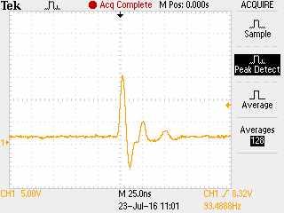
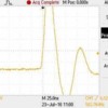
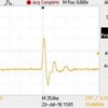
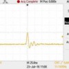
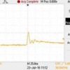
Well, as a science project I hooked up an oscilloscope to a Fastrack switch motor. It quickly became apparent that these motors are suitable for continuous duty only at very low voltages, so I did my tests at 1.5 VDC on the motor. 

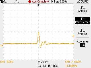
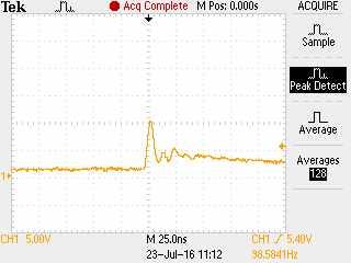
Screen shots attached are self explanatory. Note that even at a motor voltage of 1.5 transients of dozens of volts exist, but they are of exceedingly narrow width. I repeated the same test with a 1 uF mylar cap, a 10 ohm resistor and both attached to the motor leads. Note that the resistor alone is the most effective.

I think I would place one of your 22uH chokes directly in series with the motor leads as an experiment.


No suppression

1 uF capacitor alone

10 ohm resistor and 1 uF capacitor

10 ohm resistor alone

Attachments

Images (4)
  • No suppression
  • 1 uF capacitor alone
  • 10 ohm resistor and 1 uF capacitor
  • 10 ohm resistor alone
Last edited by PLCProf
Oman posted:

Since the regulator employs fold-back current limiting and thermal shut down, it must be a voltage issue. Are you sure you are not exceeding the input voltage rating, 30 volts? 

Quite sure, I'm applying 12VAC to the input of the supply.

GGG posted:

No expert in this area, but how about the fact your pulsing DC input power instead of providing filtered DC.  Your trying to do it with the large CAPs at input.  They show this used with a 12VDC input and only .1uf input cap.   G

 Good thing you said you were no expert.   If you look at almost any properly designed three-terminal regulator circuit, you'll see that the filter caps are on the input rectified DC power, the regulator will go nuts with half-wave DC on the input.  Trace out the three components on the Lionel smoke unit, they have the diode, cap, and the regulator in that order.  The 100uf cap is on the input side of the regulator.  The output of the regulator goes directly to the motor, and they don't fry when you turn them on.

There filtering on the input side, that's where it's needed.  There's nothing wrong with the input power.


Attachments

Images (1)
  • blobid0

Well, the smoke heater doesn't have any effect, I'm not powering the smoke heater.  My test is with a bare smoke motor on the bench.  I've never had this kind of issue with any regulator in the past, and the speed in which it dies is astounding, it's truly a fraction of a second!  Hard to imagine an overload would damage it since it's supposed to have current limit protection.  Certainly you'd get a bit more warning!

The data sheet claims...

• Stable with Ceramic Output Capacitors
• Current Limit Protection with Current Foldback

I'm just amazed at the speed of the failure, and I'm 3 of 3 instant failures.  One failed shorted, which was interesting, the little motor got about 16-17 volts DC, boy did it wake up!   The supply works perfectly into a resistive load that puts a 100ma load on it, and the motor only draws around 35-40ma.  I'm thinking it has to be some sort of spike issue, but I'm a little surprised it gets past the cap.  The most surprising thing is there are thousands of those motors in locomotives with a similar circuit with no output protection at all, and they seem to work fine.

That was my first thought, back emf but maybe just an impulse and resonance. I'm wondering if some wire resistance and capacitance, in the real circuit application tends to damp the resonance...like the waveforms above may indicate...and why it works in use.

What does the circuit look like in the engine? Fet switch in line, etc.?

Last edited by cjack

I was actually just making a generic 5V supply.  Just cobbling the three components that Lionel uses together on the bench, 1N4003, 100uf 35V cap, and the LM70L05 regulator runs the fan fine.  The "standard" wiring for the Lionel 27 ohm fan power is easily determined by looking at the simple wiring on the smoke unit. 

The reason that when the smoke resistor opens it kills the fan is due to the nature of the triac circuit feeding it.  This is the same reason that when you use LED lighting, you have to supply a load on the headlight circuit or the lights won't light.  The smoke and lighting triacs need a certain load to trigger, either a .01uf cap or a 470 or smaller resistor is required to trigger them.  The diode in the smoke fan power supply prevents the smoke triac from triggering without the extra load of the smoke resistor.

John I understand the caps are required at the input, but is the SMD power supply the same design as the through hole reg used by Lionel and MTH.  Lionel uses the same single diode rectification to power the regulator, you say you see a lot of those blow too.  MTH does not.  They use a FWBR to create filtered DC to power the 5VDC regulator.  I rarely see the regulator go bad.   That was my point.  Use a 9V battery to power the device and see if it still blows immediately.  If not the problem is not the load, rather the input power.  I just attack these issue from a logic perspective.  If that is not it, I assume the device is not meant to do what you want with a motor.  So throw on a flash back diode or use another regulator.  G

I don't doubt that the full wave bridge is a bit more robust if you draw enough current, but for 40-50 ma with 300uf filter, I should have plenty of capacitance to properly feed the regulator well within it's specifications.  When running a 100ma load on the supply, I see virtually no output ripple, so it's not current that's the culprit here.

However, my real concern is the instantaneous nature of the failure.

Some comments in no particular order:

1. The smoke motors I've seen have a DC-resistance of around 10 ohms.  So when you say the motor current is about 50 mA, aren't you referring to the steady-state current when spinning?  When you first start the motor, if applying 5V, the current "wants" to be 5V / 10 ohm or 500 mA.  Of course the regulator, whether it be the 78L05 or your MCP1804 will immediately go into current limiting.  The observation is the failures are occurring on startup (motor initially stopped) when the regulator is in current-limiting mode.  This may mean absolutely nothing.

2. Several comments bring up "back-emf" from the motor as some kind of culprit.  The back-emf voltage is of the same polarity as the applied voltage.  And the magnitude of the back-emf is less than the applied voltage.  So if you drive +5V DC into the smoke motor and quickly disconnect the drive while measuring the voltage across the motor, the back-emf will be some voltage less than +5V DC and dribble down to 0V in a second or so as the motor spins down to a stop.  So back-emf per se does not generate negative voltages.  Depending on perspective, back-emf actually helps you since as the motor spins up the current draw goes down.

3. What will generate nasty spikes is the inductance from the motor windings/coils.  Since smoke motors are typically can DC motors, these use commutating brushes making/breaking contact typically 3 times per revolution.  I agree with comments that spikes may be the issue.  And since the so-called fly-back (not sure I've heard the term flash-back used) voltage from the inductance is proportional to the size of the interrupted current (V = -L di/dt), I can see how the condition is worse during startup when the motor current is 5-10 times the normal operating current.

4. GGG makes an interesting observation about the half-wave input.  Note that the MCP1804 datasheet specifies an Absolute Max Output voltage of (Vin + 0.3V).

Untitled

If during startup, the current is limiting at 200mA (per MCP1804 datasheet), then the input voltage at the 300uF capacitor is collapsing at a rate of about 0.7 V/msec (dV/dt = I/C).  So in the 8.3 msec half-cycle when no track voltage is present, the MCP1804 input voltage drops by about 6V DC.  I was imagining a potential scenario where the motor is spinning up (creating a back-emf voltage).  At some point the positive back-emf voltage or 2, 3, 4 V DC might actually exceed the MCP1804 input voltage by more than 0.3V during the opposite half-cycle.  But if you're confirming there is no input ripple at 100 mA, then this is probably not an issue.  As shown in their diagram, the MCP1804 appears to use a FET which has its intrinsic diode from Vout to Vin; you've probably seen 78xx application notes where this diode must be supplied externally in certain circumstances.

So what to do.  I'd send a question to Microchip/T.I. and get their expert opinion.  Unlike the 78L05 datasheet which provides an equivalent circuit schematic of the regulator, the MCP1804 datasheet only gives a "functional block diagram" which is somewhat stylized making it hard to reverse-engineer what is really going on inside.  The failure mode differences between CMOS (MCP1804) vs. bipolar (78L05) is a complex subject. 

OTOH if you have nothing better to do and want to experiment, it appears to be an issue of how to keep the output voltage within the allowed range or practically speaking messing around with diode/TVS clamps and/or capacitors.

Attachments

Images (1)
  • Untitled
Last edited by stan2004

My error on flash back, fly-back is correct term.  Quick post before getting off to the beach.  From what I have seen on these SMD type power supplies, they are meant to make DC from DC; and have a lot of filtering/conditioning on the input and output.  Hence my original comment.  By the way MTH motor ohm out at 12 ohms.  G

Last edited by GGG
stan2004 posted:

OTOH if you have nothing better to do and want to experiment, it appears to be an issue of how to keep the output voltage within the allowed range or practically speaking messing around with diode/TVS clamps and/or capacitors.

While it's enticing to actually tinker with it, I think I've about reached my "tinker" potential.   I am going to send a query to Microchip, that's a good idea.

GGG posted:

My error on flash back, fly-back is correct term.  Quick post before getting off to the beach.  From what I have seen on these SMD type power supplies, they are meant to make DC from DC; and have a lot of filtering/conditioning on the input and output.  Hence my original comment.  By the way MTH motor ohm out at 12 ohms.  G

If you look at the MCP1804 datasheet, they actually specify ripple rejection.  Also, I don't see anything in the datasheet that suggests this isn't suitable for common three-terminal regulator applications.

trainman129 posted:

Probably a silly question but are you sure that the connections are right? Its happened before and drives you nuts...

Just a thought.

Yes, the connections are correct.  Let's see transformer power on the input and the motor on the output, the only four connections I could make.  Even I can't screw that up!

It really seems like a load problem. Note that Absolute Maximum negative voltage on the output is -0.3 volts. If you exceed that voltage from back EMF, that tiny diode inside the chip is going to fry. You cannot clamp to less than 0.3 volts with regular diodes or TVS, hence why I suggested a Schottky diode, but that may not even keep it below 0.3 volts. I still think that 10X on the output cap would work.

Just a thought and along the lines of trainman129's post, could the components be marked wrong as to the pin outs? I have not seen this with an electronic component, but in my working life I did run across some devices with the ports/ins/outs, etc. marked incorrectly or the data sheets were incorrect. I don't know what the chances are of this happening on an electronic component though?

Well, first off, I use all these components in other projects except for the regulator.  Also, the supply works perfectly as expected with a resistive load on the bench, hard to believe it would do that being wired wrong.

Keith, I agree, it seems to be something about the motor characteristics, it's just pretty odd that it would instantly cook the regulator.  Obviously, this particular 3-terminal regulator is very touchy for some reason.  I used the same regulator powering a uP, no problem with it there.

Well, I was going for a better regulator, but apparently I made a poor selection.   It worked fine on a prototype audio module, so I figured I'd try it here.  I'm also rethinking the concept instead of putting more time into that one.  I may go with a proven regulator like the LM317T for a module, and add variable voltage.  If I change the board, I might as well make it more flexible.  I'd also consider the half-wave/full-wave option to give it a bit more flexibility.

I did order a different regulator with the same footprint to try in this board, it'll be interesting if it has the same issues with motors.

gunrunnerjohn posted:

Well, I was going for a better regulator, but apparently I made a poor selection.   It worked fine on a prototype audio module, so I figured I'd try it here.  I'm also rethinking the concept instead of putting more time into that one.  I may go with a proven regulator like the LM317T for a module, and add variable voltage.  If I change the board, I might as well make it more flexible.  I'd also consider the half-wave/full-wave option to give it a bit more flexibility.

I did order a different regulator with the same footprint to try in this board, it'll be interesting if it has the same issues with motors.

Dale Manquen posted:

Motors and loudspeakers are both inductive loads.  It is common to include a shunt "damper" across the output consisting of a series R and C to swamp the inductive effect of the load and connecting cables at high frequencies.  Maybe you could try the same thing.

I was working on the KISS principle, since I don't see them on any other smoke fan motor regulator, I didn't really think I needed them.  I even tossed in the 1uf output cap that most don't have.

gunrunnerjohn posted:

I did order a different regulator with the same footprint to try in this board, it'll be interesting if it has the same issues with motors.

Was it a CMOS regulator (vs. a bipolar)???

Here's a scope shot of a 78L05 (bipolar) driving an MTH smoke motor during startup.  This was with NO capacitor on the 78L05 output.  This wild negative voltage excursion (green trace) of about -2V is from a commutation spike as I mentioned earlier.  The red trace is the current into the motor.  This is NOT a result of back-emf.  I don't know what you said in your inquiry to Microchip/T.I. but hopefully you did NOT refer to back-emf as the culprit as you will lose credibility with an App Engineer.  The 78L05 was in current-limiting in this transient capture (the entire screen is only 5 microseconds of time!). 

IMG_1122

The intrinsic protection diode structure in CMOS devices (if in fact this is  what's in-play with the MCP1804) is what I believe is the issue...but a Microchip App Engineer would be able to say for sure; they should be able to tell you how much "clamping" energy can be handled. 

Sure, you can spend the time to analyze clamping energy, currents, choose capacitance, blah blah blah, but why bother?   If you really need LDO or the lower quiescent currents offered by CMOS technology, then that's one thing and we can get into it (yawn!).  But the 317 bipolar devices are tried-and-true and probably even cheaper.  Your LED module using the 317 remains the gold-standard of voltage regulation for O-gauge AC!

Attachments

Images (1)
  • IMG_1122
Last edited by stan2004

Thanks Stan, I just asked them why they thought the regulator was failing in my application.  Truthfully, when I picked it, I didn't give the CMOS angle much thought, obviously a serious mistake on my part!   I've used so many 3-terminal regulators without any issue, I kinda' failed to pay attention.  Lesson learned.   Fortunately, most of these lessons are fairly cheap.

Add Reply

Post

OGR Publishing, Inc., 1310 Eastside Centre Ct, Suite 6, Mountain Home, AR 72653
800-980-OGRR (6477)
www.ogaugerr.com

×
×
×
×
Link copied to your clipboard.
×
×