Hi All,

so I’m adding red LED’s to the tail end of a 3D printed body. I plan on using either a red or white LED into an MTH subway car red tail light lens. A friend gave me the LED’s and the resistors, pictures attached. My question is are the resistors supposed to get very hot? I have a small MTH Z1000 brick for test power on my bench. I’ve never added LED’s to a car yet, but the resistor seems hot to me. Thx

Brian NY58B31A58-A976-4699-83F3-75686FABA7EDA802A457-58F1-4569-A3A0-3F2D30F59538

Attachments

Images (2)
  • 58B31A58-A976-4699-83F3-75686FABA7ED
  • A802A457-58F1-4569-A3A0-3F2D30F59538
Last edited by MCD4x4
Original Post

Replies sorted oldest to newest

A few comments:

1.  While you can run LEDS on track power or other AC source, it will significantly shorten their life. You should use a diode and a resistor in series with the LED.  For up to 18V track power, a standard 1N4003 diode and a 470 ohm 1/4W resistor will handle one standard LED.  That will run 10 mA through the LED.  You can go brighter (up to 20 mA) with a lower value resistor.

2.  Online LED calculators will tell you what ohm resistor as well as the wattage rating needed to dissipate the heat generated.  These calculators are very useful, but they assume DC voltage.  It gets complicated when you are rectifying AC with a diode.  18v AC effectively produces only 8v DC (14VAC gives 5.6V DC, and 10VAC gives 3.8V DC).  Here is a "math-fun" discussion of doing the rectified DC voltage calculations.  It also shows the Diode/Resistor/LED circuit.  

To use the LED calculator, you plug in the supply voltage (DC), voltage rating of the LED (they have hints to help you determine that), current you want to supply the LED (usually 10-20 mA depending on brightness desired), and number of LEDs in series in the circuit.

Bob

@RRDOC posted:

A few comments:

1.  While you can run LEDS on track power or other AC source, it will significantly shorten their life. You should use a diode and a resistor in series with the LED.  For up to 18V track power, a standard 1N4003 diode and a 470 ohm 1/4W resistor will handle one standard LED.  That will run 10 mA through the LED.  You can go brighter (up to 20 mA) with a lower value resistor.


Bob

Bob,

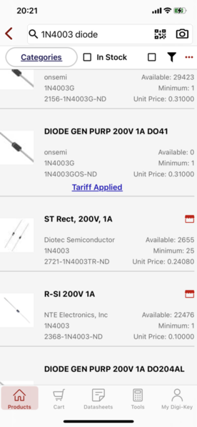
when I look up the number diode you provided on Digi-key, three come up with no letters after it, picture attached. Is this it? Like I mentioned to Arthur, I’d like to avoid the heat because the wire runs underneath the seating  also as Train’s enter and leave the power block the voltage could go up as high as 21 VAC.  

Brian NYC3424376-6E9D-4FBC-9A74-FC14D2A784E5

Attachments

Images (1)
  • C3424376-6E9D-4FBC-9A74-FC14D2A784E5
Last edited by MCD4x4

If the resistor gets hot, its wattage rating is too low.  Use a resistor that has a higher power rating. The ones you have are 0.25W as indicated on the package.

Arthur, a higher power rating, what power rating would be needed to avoid the heat? These wire run under the seating in an 1/8” space. Another thing to keep in mind, while Train’s enter and leave the block, that 18 volts could rise as high as 21 VAC I would imagine.

Brian NY

Last edited by MCD4x4

There seems to be some misunderstanding about resistor wattage ratings and heat transfer.

Resistors with a higher wattage rating can dissipate more electrical energy and heat (measured in Watts) before failure.

Given two independent resistors of equal resistance, one 1/4 Watt and one 1/2 Watt.  If 1/4 Watt of power passes through each, each resistor will radiate 1/4 Watt of heat.  

In other words, all other factors being equal, resistors with different Wattage ratings will transfer the same amount of heat into their surroundings.

I would suggest in addition to using blocking diodes to also select resistors with higher resistance values.  This will reduce the current flow in the circuit and the heat.  If possible relocating the resistors where they have more air flow around them would be a good idea.

Last edited by SteveH

Bob, (rrdoc) pretty much summed it up. You pick a resistor value based on applied voltage assuming 10-20ma LED current. If you are using unregulated 20 VAC track voltage then peak is 28 volts (20 x 1.414) For 10ma current you would need a 2800 ohm resistor.

480 ohm is ok for 5 volts. The problem isn’t the wattage rating but the resistance value plus the missing diode. 1/4 watt is more than enough. Even 1/8th watt.

Not the best practice to run LEDs off track power, better to just use a zener diode and resistor to get your 5 volt DC, LM78L05 three terminal regulator, or get a buck boost convertor as they are pretty inexpensive these days. Then skip the diode.

Pete

Last edited by Norton

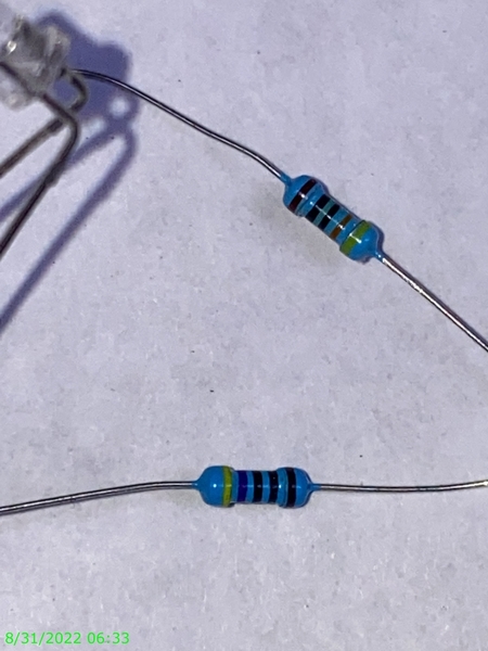
Those "appear" to be 47 ohm resistors, which would be WAY too low a value for 18 VAC transformer power to LED's.  Are the first four bands really yellow, purple, black, black?  If so, they'll kill the LED's in short order.  470 ohm will result in about 20 ma in current, consider using 1K 1/4w resistors with a diode for 18 VAC track power applications.

Those "appear" to be 47 ohm resistors, which would be WAY too low a value for 18 VAC transformer power to LED's.  Are the first four bands really yellow, purple, black, black?  If so, they'll kill the LED's in short order.  470 ohm will result in about 20 ma in current, consider using 1K 1/4w resistors with a diode for 18 VAC track power applications.

GunnerJohn


Sorry for the delay, had a vacation week to go on. heres a close up of the resistor with and without flash so you can see what it is. Also The diodes came in, I’m assuming the diode goes closer to the power source, than the resistor and LEDs. The diode itself, does it mater which way it’s soldered in, stripe towards power or load?
8FB614FA-9B64-40F0-8338-923688F7130CBE1D4411-FF68-4C87-A3CD-1D5975A79B83

any of these good?

18B596A4-477F-45F6-850E-9332AB7C7074

Attachments

Images (3)
  • 8FB614FA-9B64-40F0-8338-923688F7130C
  • BE1D4411-FF68-4C87-A3CD-1D5975A79B83
  • 18B596A4-477F-45F6-850E-9332AB7C7074
Last edited by MCD4x4

Was there a spec for the LED current draw?  A 5 volt LED drawing 5MA is common, 5 ma draw across 47 ohms is only 2.35 volt, so anything above a 7 VDC supply as a supply will tax the LED.  Also, 16 VAC track voltage is 16VAC RMS or the equivalent to 16 VDC,  Actually you have 2.828 times the volts on the track or 45 volts peak to peak, the LED will try to conduct for 1/2 that cycle or a peak of 22 volts at full throttle, so that 47 ohm resistor is way too small in all accounts.   A single diode to rectify the track volts will give you a 22 volt 30 cycle per second peak at 16 track volts, if you filter this with an electrolytic, you will get about the same voltage with no load, but it will be steady DC which will drop to some value when you put a load on it.  The problem occurs when you run slow to fast, your track volts goes up and down, so does your LED supply.  Now you have to regulate it such that minimum track volts to full track volts you get 5 volts on the LED.  There is no resistor alone you can put in that circuit to handle min track to full track voltage.  I use a bridge rectifier which gives me a 60 cycle ripple for better filtering with a smaller UF value cap, and a 7805 3 terminal regulator which puts out 5 volts for the full track volts, and the LED stays lit for a moment due to the caps charge, when the throttle is at zero.  A lot more complicated for sure, but allows LED lighting when using standard variable AC track control. There is also a simpler way but needs a bit more math.  Rectify the AC track volts, filter it with a large UF value cap, run that output through another resistor to a 5 volt zener diode, and the zener will regulate the LED voltage, and keep the lights lit as long as the cap has a charge greater than 5 volts.  You have to know the current draw of all the LED's to determine the value of the zener current range needed and the size of the zener dropping resistor with LED load.

Last edited by CALNNC

That resistor "looks like" it's yellow, purple, black, black, and I can't really tell if the last band is black or brown, I'm guessing brown for 1%.  In that case, it's a 470 ohm resistor.

From 5-Band Resistor Color Code Calculator.

The diode cathode (stripe) should be toward the positive lead of the LED, the unbanded end goes to track power.

Attachments

Images (1)
  • mceclip0
In that case, it's a 470 ohm resistor.


John, should I find a 1K 1/4 watt instead.

The voltage is between 18 and 21 on the Z4000. It varies when engines enter and exit the block. Running multiple trains sometimes requires raising the voltage. If left at 18, and another train or two enter the block it drops to 14. What’s the best way to handle that, raise the voltage?

@CALNNC posted:

There is also a simpler way but needs a bit more math.  Rectify the AC track volts, filter it with a large UF value cap, run that output through another resistor to a 5 volt zener diode, and the zener will regulate the LED voltage, and keep the lights lit as long as the cap has a charge greater than 5 volts.  You have to know the current draw of all the LED's to determine the value of the zener current range needed and the size of the zener dropping resistor with LED load.

Virtually all the consumer grade LED's are rated at 20ma.

Instead of fooling around with Zener diodes and resistors, why not use the CL2?  The cap really doesn't have to be that large for an LED or two, 100uf at 35V is plenty.

Since the CL2 is a constant current source, you can also string one to four LED's in series and get the proper intensity from all of them.

Attachments

Images (1)
  • mceclip0

I'd probably use a 1K resistor.

Also, if the voltage drops from 18 volts to 14 volts, I'd strongly suspect a problem, that's a huge voltage drop!  Is that at the transformer?

John the 1K 1/4 watt resistors are sold in 1% and 5%, which one is beater for the application?

after work tomorrow I put three engines in one black and let you know the difference on the Z4000 readout.

Brian NY

@MCD4x4

Since you already have a bunch of 470 Ohm resistors, you could connect 2 of them in Series to equal 940 Ohms.  That's only slightly more current running through the diode compared to a single 1K Ohm resistor and well within the LED's specification.

Also the heat generated by each resistor would be roughly half of a single 1K.  If they are physically separated by a bit of space these two daisy chained resistors would spread the heat more.

Last edited by SteveH
@SteveH posted:

@MCD4x4

Since you already have a bunch of 470 Ohm resistors, you could connect 2 of them in Series to equal 940 Ohms.  That's only slightly more current running through the diode compared to a single 1K Ohm resistor and well within the LED's specification.

Also the heat generated by each resistor would be roughly half of a single 1K.  If they are physically separated by a bit of space these two daisy chained resistors would spread the heat more.

Good idea, thank you


Brian NY

1% or 5% makes no difference for the LED application, it's not that critical.  Also, the 1K resistor will be dissipating half the power as the 470 ohm resistor, so heat is really a non-issue with the higher value.  FWIW, I've been using 470 ohm 1/4W resistors with a single white LED from track power for many years, never had a problem.  You can certainly use two 470 ohm resistors in series, of course that increases the bulk.

18 to 14 volt drop under load, remember that copper wire is a very low value resistor, the smaller the wire the greater the resistance.  If you are using some small stuff like #22 solid, that can make a big difference compared to a size like #16.  Measure the track volts under load,  then measure the volts at the transformer terminals to see how much you are losing in the wiring and connections.

@CALNNC posted:

18 to 14 volt drop under load, remember that copper wire is a very low value resistor, the smaller the wire the greater the resistance.  If you are using some small stuff like #22 solid, that can make a big difference compared to a size like #16.  Measure the track volts under load,  then measure the volts at the transformer terminals to see how much you are losing in the wiring and connections.

I have to check this and report back


Brian NY

@MCD4x4 posted:

Ok, so I wired, the diode with the stripe facing the LED, two resistors and two LEDs. When wired like this only one LED works. If I unsolder one LED on the negative side, each one will light as I jump the negative back and forth. Do I have to used a diode and two resistors for each LED?

Remember, both the diode and the LED have polarity, so they have to both be wired in the correct polarity for things to work.

Wire the banded end of the diode to the positive side of the LED.  The positive terminal is the longer lead, and also if the leads are already cut, it's the smaller electrode inside the LED.

Note the anode (long lead) has the smaller electrode.  Also, the flat spot on the LED is on the cathode (negative) side.


In order for to function with a diode, the banded of the diode has to be wired to the + lead of the LED, the hot side of the power goes to the unbanded end of the diode.  Also, if you have two LED's to wire them in series, you wire the negative of one LED to the positive of the other LED, then the negative of the second LED goes to the common power connection.

Think like batteries in a battery holder.

Attachments

Images (2)
  • mceclip0
  • mceclip1
@MCD4x4 posted:

John the 1K 1/4 watt resistors are sold in 1% and 5%, which one is beater for the application?

The "percentage" rating is just the average accuracy of the resistance rating in a batch of that type of resistor -- the lower the percentage, the closer any given resistor in the batch will, on average, be to the rated value (and the more accurate the rating, the higher the price). Unless you need a precise resistance (and you really don't here!), you can safely ignore the percentage rating, as John said. Even if you're working with resistors with a lower accuracy rating, actually *measuring* the resistance of any given resistor will enable you to be sure the *actual* resistance is close enough to what you need.

Oh, and a brief coda to John's reply on polarity: garden variety resistors do *not* have a polarity and can be connected in either direction. Also, when you are wiring components in series (with no components tapping into or paralleling any of the serial components), the order in which they are connected does not matter (or rather, you can freely mount them as space and other considerations -- such as heat dissipation -- suggest or dictate). I've seen a lot of hobbyists and electronic techs who suggest a particular order (for instance, attaching the resistor to the positive or negative LED lead) but AFAICS that's just a matter of habit and consistent work practices rather than electrical necessity. OTOH, if a component *does* tap into a serial chain (as, for instance, a smoothing capacitor after a voltage-limiting resistor), you do need to be sure it is between the appropriate components.

In order for to function with a diode, the banded of the diode has to be wired to the + lead of the LED, the hot side of the power goes to the unbanded end of the diode.

Maybe that where I went wrong. I wired the diode closest to the power with the two 470 in between the positive side of the resistor.


does it mater which way the resistors are facing?

Brian NY

Last edited by MCD4x4

The current through two parallel LED's or a single LED with a resistor dropper will result in the same current through the resistor.  LED's have a specific operating voltage, for white LED's it's around 3 volts. If you had 12 volts across a resistor & LED, the resistor is dropping 9 volts.

If two LED's are in parallel, they're still running at 3 volts, and the resistor is still dropping 9 volts, the power is the same, the LED's just aren't as bright as they're only receiving half the current.

@MCD4x4 posted:

Maybe that where I went wrong. I wired the diode closest to the power with the two 470 in between the positive side of the resistor.

does it mater which way the resistors are facing?

You can put the components anywhere, but any polarity sensitive components MUST be in the correct polarity!  Obviously, the resistors have no polarity and can go in either direction, but the diode and LED do have polarity.

The current through two parallel LED's or a single LED with a resistor dropper will result in the same current through the resistor.  LED's have a specific operating voltage, for white LED's it's around 3 volts. If you had 12 volts across a resistor & LED, the resistor is dropping 9 volts.

If two LED's are in parallel, they're still running at 3 volts, and the resistor is still dropping 9 volts, the power is the same, the LED's just aren't as bright as they're only receiving half the current.

Err, that's not exactly how I recall Ohm's Law working.

Unless there's some special property of LEDs I'm unaware of, the resistance of each LED would be constant regardless of how wired (assuming proper polarity).  If the total voltage applied to the circuit is 12 volts, the resistor used is 470 ohms, and the LED is "seeing" 3 volts (a quarter of the total voltage), the LED resistance should be something around 157 ohms, or 1/4 the total resistance of 627 ohms (470 + 157), and the circuit should draw about 0.02 amps (I = V/R = 12/627).

OTOH, if you add a second LED in parallel with the first, the total resistance will drop a bit, to 548 ohms (470 + 157/2), the current will rise to a bit under 0.022 amps (I = V/R = 12/548), the resistor will "see" (or "drop") about 10.29 volts, and the pair of LEDs will "see" only a bit over 1.7 volts. As you said, each LED will carry one-half the total current, or about 0.011 amps each, and since that's at a lower voltage, they will each use less power (and be much dimmer) than when each is wired alone with a separate resistor. Conversely, the dual-LED resistor will "see" a higher voltage and slightly more current, and thus will have to dissipate more power.

My apologies if my back-of-the-envelope calculations are off a bit, but I think I'm correctly applying Ohm's Law as I learned it many years ago.

@Steve Tyler posted:

Err, that's not exactly how I recall Ohm's Law working.

You're missing the unique property of LEDs.  One or a dozen white LED's in parallel will always have about a 3V drop across them, they're current mode devices and they have a very sharp voltage/current curve.  Hence the series resistor, whatever it's value, will always be dropping the same amount of voltage.  If it's dropping the same amount of voltage, it has to also be dissipating the same amount of power and carrying the same amount of current!  The LED's are simply splitting the current between the parallel bulbs, so if you have 20ma with one LED, and you add three more parallel LED's, each LED will be using 5ma.  There will be a very slight difference in power through the resistor, but at 1.7 volts a white LED draws no current because it's not lit!

Don't take my word for it, back to the workbench with some LED's and resistors, let me know how you make out.

Ohm's Law is alive and well.

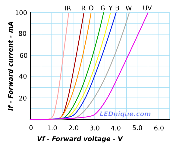
IV curves | LEDnique

Last edited by gunrunnerjohn

You're missing the unique property of LEDs.  One or a dozen white LED's in parallel will always have about a 3V drop across them, they're current mode devices and they have a very sharp voltage/current curve.  Hence the series resistor, whatever it's value, will always be dropping the same amount of voltage.  If it's dropping the same amount of voltage, it has to also be dissipating the same amount of power and carrying the same amount of current!  The LED's are simply splitting the current between the parallel bulbs, so if you have 20ma with one LED, and you add three more parallel LED's, each LED will be using 5ma.  There will be a very slight difference in power through the resistor, but at 1.7 volts a white LED draws no current because it's not lit!

Don't take my word for it, back to the workbench with some LED's and resistors, let me know how you make out.

Ohm's Law is alive and well.

Mmm, well, I don't have any LEDs easily at hand that don't already have resistors already wired in, but I just took possession of an arduino kit that *does* have LEDs and resistors aplenty, and I'll let you know what I find out after I unpack it and set up a test bed. However, I *do* know the resistance you're supposed to add to protect an LED varies with the supply voltage, so I question whether an LED will *always* have a 3 volt drop across it regardless of the resistance or the applied supply voltage, if I correctly understand your assertion.

You can put the components anywhere, but any polarity sensitive components MUST be in the correct polarity!  Obviously, the resistors have no polarity and can go in either direction, but the diode and LED do have polarity.

John, the LEDs are red, they’re tail lights. The problem I’m having is when I wire up as you suggested, only one LED will light up. If I unsolder the negative side and then test each one all LEDs work. When I put them back together only one will light up.

Brian NY

@MCD4x4 posted:

John, the LEDs are red, they’re tail lights. The problem I’m having is when I wire up as you suggested, only one LED will light up. If I unsolder the negative side and then test each one all LEDs work. When I put them back together only one will light up.

I'd need to see EXACTLY how you're wiring the LED's to know what's happening.  If you wire them in series, I certify that either none or all will light.

@Steve Tyler posted:

Mmm, well, I don't have any LEDs easily at hand that don't already have resistors already wired in, but I just took possession of an arduino kit that *does* have LEDs and resistors aplenty, and I'll let you know what I find out after I unpack it and set up a test bed. However, I *do* know the resistance you're supposed to add to protect an LED varies with the supply voltage, so I question whether an LED will *always* have a 3 volt drop across it regardless of the resistance or the applied supply voltage, if I correctly understand your assertion.

Did you look at the image below I previously posted?  Follow the white line, that's for a white LED.  Note that the current through the LED at 2.0 volts is maybe a milliamp or two, and at 3.0 volts it's 20 milliamps.  By the time you get to 4.0 volts you're over 60 milliamps and the LED is on it's way to LED heaven.

The LED is a non-linear device, it doesn't track with Ohm's Law like adding a resistor as it's replacement.

I'll give you a small bone, it won't have exactly 3 volts across it.  However, if you assume it has 3 volts and pick the resistors accordingly, everything will work out just fine.  The LED will not limit current (until it blows), it's the resistor that determines the current flow through the LED.

Add Reply

Post

OGR Publishing, Inc., 1310 Eastside Centre Ct, Suite 6, Mountain Home, AR 72653
800-980-OGRR (6477)
www.ogaugerr.com

×
×
×
×
Link copied to your clipboard.
×
×