
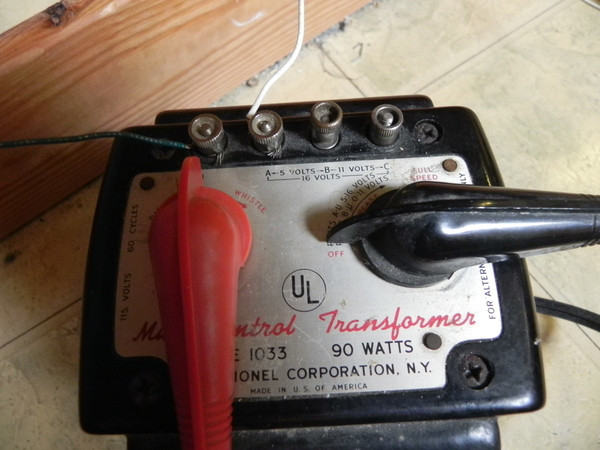
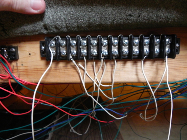
I have two transformers, a ZW and a 1033.  The ZW controls most everything, switches, lockons, accessories, lights.  The 1033 controls lights.  The 1033 is connected from the second post from the left and runs to a terminal strip that is connected to many of my lights.  My 6 streetlights have two wires, one for ground, and one to be connected to the terminal strip that lights are connected to.  Recently, none of my 6 streetlights worked.  I tested them by attaching one wire to the center rail of my O gauge track (Lionel), and one wire to an outer rail.  The lights worked when I did that.  When I connected two of the lights to the terminal strips (lights and ground), they worked.  Two other lights did not work.  All four lights worked when I tested them on the rail.  The way I have the 1033 connected, lights should power on when I move the lever back and forth, but nothing happens - the lights don't turn off or go on.  Could there be a problem with the 1033?  The 195 floodlight works when I use the test method of connecting it to a rail, but not when I connect it to terminal strips.  What the devil is happening?   

Original Post

Replies sorted oldest to newest

Should the wire from the 1033 be directly connected to the streetlights terminal strip?  If so, how?

Do you have just one wire connected to the 1033?

Explain, with photos as needed, exactly which posts you are using on the 1033 (A,B,C,U) and where the connection points on the layout are made. Are you using a common ground? Are you using the 1033 common post "A" for common/return?

I have only one wire,connected to the 1033...

Well, there's your problem. The 1033 is a two-wire transformer.

With "A" as the common/return, "U" is the variable 5-16 volt output, B is the 5 volt fixed post, C is the 16 volt fixed post.

Alternately, "B" can be used as the common/return, with "U" as the variable 0-11 volt output, C as the 11 volt fixed post.

Last edited by ADCX Rob

Got my answer - A connects to the terminal strip, U connects to ground/common on the ZW.  I'll soon connect the ground wire and see what happens.  Stay tuned.

Actually, the first post, "U", connects to the terminal strip, the second post, common post "A", connects to ground/common on the ZW("U").

Single train transformers use "A" as common.

Last edited by ADCX Rob

Tried all common posts across the top row of posts on the ZW.

All common posts across the top row of posts on the ZW are just that - common. They are all electrically the same.

Connect the ground wire from 1033 "A" post to any ZW "U" common post.

Phase the two transformers as per these instructions. BUT REMEMBER, "A" on the 1033 is common.

Could it be I have too many connections on my terminal strips?

No.

Last edited by ADCX Rob

The other wire runs from the terminal strip to the U post on the 1033.

That accounts for only half of the circuit, assuming one wire from each lamp is connected to your terminal strip... let's call that the "hot" side of the lighting circuit as this is controlled by a variable transformer output.  Where are the remaining wires, one more from each lamp, connected to?

The 1033 (ground or U post) and the A post should go to the lights

The 1033 U post is not common, and is not ground... It is directly connected to the throttle, direction, and whistle circuits and you do not want to use this as a common return on a common ground layout.

"A" is the common post on the 1033 and its variants.

Last edited by ADCX Rob

So, I have to connect the ground wire from the 1033 A post to the ground post on the ZW, and the terminal strip wire from the terminal strip to the B or C post on the 1033?

No idea where you got that from asking where the second wire from each light is connected, so I will say no.  The 1033 "U" post is your "hot" variable voltage for adjust lighting level, assuming one wire from each lamp is connected to your terminal strip from post U. That's half the circuit.

Now, the other half, common/ground/return, must be connected to the "A" post of the 1033. This connection can be made anywhere on the layout if you have phased the ZW and 1033 as per these instructions. ... at any #2 lockon clip, any ZW "U" post, or the 1033 common/ground/return "A" post(they are all electrically the same after proper phasing). That completes the circuit, and gives you 5-16 volts to regulate the brightness of your lights.

You might have a terminal strip of sorts that you haven't made clear what it is or what is connected to it, but there is no magic involved here - terminal strips, barrier bars, etc., are just convenient places to connect several wires to power so you aren't trying to stack 9-10 wires onto a binding post at the transformer.

It looks like you may be complicating this for yourself by using terminal strips and including the ZW in the circuit. To boil this down to the bare minimum... all you need is one wire from each light to the hot "U" post of the 1033, and one wire from each light to the common "A" post to get 5-16 vols to your lights.

Last edited by ADCX Rob

Each streetlight has 2 wires.  One wire is connected a terminal strip for ground,  the second wire is attached to a terminal strip for lights.  That second terminal strip is connected to the 1033 on its B post.  Is that the way to do it? A ground wire runs from the A post on the 1033 to a ground post on the ZW. 

All 6 streetlights are wired this way.  Only 2 of 6 streetlights work.  Why are only 2 streetlights working when all 6 are connected exactly the same way?

The simplest connections - start with this:

Each streetlight has 2 wires.

One wire is connected a terminal strip for ground(1033 "A" post).

The second wire is attached to a terminal strip for lights(sic).  That second terminal strip has to be connected to the 1033 "U" post for 5-16 volts(variable) or 1033 post C for 16 volts(fixed)

If you use "B" with common "A", that's only 5 volts and some accessories won't light at that low setting.

There is no way any of us could possibly know that.

The circuit HAS to be complete to work.  The popular way to work with terminal strips is to have, in your case, 2... one for "hot" and one for "ground".  ALL terminals on the ground strip must be connected to each other and to the "A" post,  ALL terminals on the hot strip must be connected to each other and to the "U" post. One wire from each light to each strip.

Here is a Lionel diagram showing 6 terminal strips - but the two large ones are really just one large & connected ground point, the other 4 are for different voltage settings/needs.

Last edited by ADCX Rob

Rob, connections from terminal strips to ZW and 1033 are correct.  However...

Could the problem be with the 195 floodlight and the streetlights themselves?  I used 18 gauge wire on the 195 and the streetlights.  The 195 and the streetlights are ancient, but the odd thing is the 195 and the streetlights worked when I tested them.  I tested them by touching one wire to the center rail of my track (O gauge), and the other wire to one of the outer rails.  I'm puzzled as to why the 195 and the streetlights work when tested, but not when connected to the terminal strips.  Any thoughts?  I'll post pictures of the 1033 and the terminal strip lights are connected to tomorrow morning. 

...the order of the posts from left to right:  U, A, B, C.

The posts are labeled very clearly on the transformer...

Swap the green wire to the common "A" and the white wire to the "hot"  "U" post and you are connected correctly.

Also, to confirm a complete circuit, move the 1033 green wire(post "A") to the ground terminal strip where half of your lights wires are connected instead of the ZW. If this circuit is controlling lights only, there is no need to have it phased to the ZW.

This will give you 5-16 volts variable to adjust your lights to your preference.

Last edited by ADCX Rob

Add Reply

Post

OGR Publishing, Inc., 1310 Eastside Centre Ct, Suite 6, Mountain Home, AR 72653
800-980-OGRR (6477)
www.ogaugerr.com

×
×
×
×
Link copied to your clipboard.
×
×