Does anyone have a wiring diagram for this terrific accessory? I have a loose wire and can't find where it might go. Thanks in advance.
Replies sorted oldest to newest
Highly suggest you post your pictures, since the parts diagram is very minimal. What color is this loose wire?
From the parts breakdown https://www.lionelsupport.com/Oil-Pump_682017
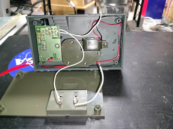
We have a DC can motor, a switch, and a rectifier and regulator PCB.
The board has silkscreen labels. Red and Black would be DC regulated output to the motor, the white wires are AC coming in

I don't know if the switch is on the AC or DC side of the circuit, but would just be in series and thus relatively simple.
Again, per the parts picture, they omitted a connector for the DC motor and appear to directly solder the wires for the DC motor to the solder pads where the jack would go. Again, wires appear to be soldered to the backside of this PCB so I think that "polarity" is correct.

Attachments
I should mention that when I apply power to the clips and touch the 2 white wires together, nothing happens.
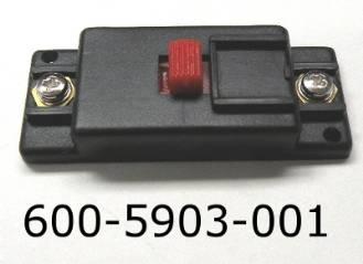
Connect the 2 white wires to run constantly. Otherwise, connect the 2 white wires to the switch per factory.
There is no switch that I am aware of. This is the 2009 version of the oil pump and not the newer plug n play.
@POTRZBE posted:I should mention that when I apply power to the clips and touch the 2 white wires together, nothing happens.
Given how weak these 3V motors are- one answer is the gearbox section grease or dirt stuck into a gear is binding the motor. I would remove the gearbox, clean the gears, apply a light grease if any, and then attempt to operate.
Just guessing, it had a problem, someone bypassed the switch, it still had a problem and you ended up with it.
I shall try these things this afternoon. Thank you. I bought this item brand new some years ago from a Lionel dealer.
@POTRZBE posted:There is no switch that I am aware of. This is the 2009 version of the oil pump and not the newer plug n play.
Sorry, I saw this in the parts listing specific to this version. https://www.lionelsupport.com/Oil-Pump_682017

I realize that now is external-

Point being, again, the white wire is just AC going into the regulator rectifier board.
Either it is bad (I consider that unlikely but anything is possible), simple enough to measure DC output at the black and red wires when AC accessory voltage is applied to the white wires.
The other option or test- just apply 3V DC to the motor using batteries or another source.
Attachments
Can the motor be wired directly thus bypassing that circuit board?
@POTRZBE posted:Can the motor be wired directly thus bypassing that circuit board?
I don't see why you couldn't. First try two in series AA batteries to make sure the motor works and you like the speed. If so, then directly wire a 3 VDC power supply bypassing the circuit board.


