Just thought I'd share an interesting project going on at the AGHR club here in LA with our telemetry train (now version 2.0).


Intro:

At the AGHR club in LA we've built a stock car with an RPI3 embedded host computer and a bunch of telemetry sensors which we call the "Telemetry Train". While some of the train's system are focused on troubleshooting power signals, DCS, and TMCC control signals (not the focus of this post), one of the other aspects is we've been exploring is using MEMS accelerometers to measure defects and kinks in the track rails as the train rolls along. 


------------------------------------------------------------------------------------

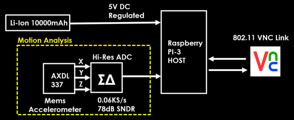
Block Diagram of Telemetry Train's Motion Processing

------------------------------------------------------------------------------------

ACC_system

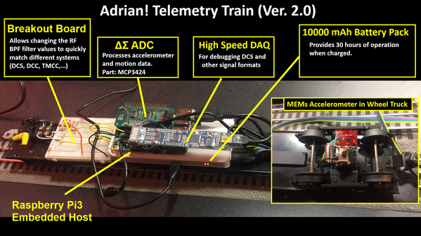
To implement the motion tracking we use a raspberry Pi3 Computer (features the Broadcom ARM BCM2837) powered by a small Lithium Ion Battery. We leverage the AXDL 337 motion sensor from analog devices to do the actual sensing of motion: ADXL337 and then read it's analog outputs with a high speed delta-sigma ADC (typically running 50-100 Hz). Generally you want good dynamic range for motion capture applications which is why a high resolution ADC is necessary, so we went with a nice MCP3424 from Microchip (http://www.microchip.com/wwwproducts/en/MCP3424) that has about 80 dB of spur and distortion free dynamic range. The MCP also has an I2C bus so it's very easy to interface with the Pi3.

ACC_assembly

As you can see in the setup picture, we have the AXDL MEMs sensor tucked into the wheel truck of the stock so that any of the bumps we hit along the layout are captured.


Capture Software:

Software wise we just have a C script that reads the I2C bus at 60 Hz or so and writes down the X,Y and Z acceleration from each sample into a csv file. The script needs to be simple in order to support the fastest possible sample rate, so it's not even conditional, we just have a for loop that runs for n increments and we tune n based on the layout length and sample rate. Samples are loaded into a large array of doubles, and then the entire array is written at the end (again file ops on each loop would be too slow for 60 Hz sampling).


Back end Signal Processing:

Finally we drag that csv into matlab and just  do a vector magnitude calculation R = sqrt (X^2+Y^2+Z^2) and do some basic linear scaling from the sensor datasheet to get the true force in Newtons. The timescale is also pretty trivial, we just scale the axis by the sample rate.

In general MEMs data is noisy, so we apply a smoothing function and just tune the span (typically we use 3-5 point span). On one hand you want to capture the violent discontinuities, but on the other you don't want to have to physically investigate every peak in 5 min of data sampled at 60 Hz. Additionally in matlab we wrote an .m script to auto align track data from multiple passes (basically a maximum cross correlation vs. time shifting function) so that we can do some basic statistics. We then adjust the confidence interval (a given feature has to show up in n out of m track traces in order to be considered a real track issue). This dramatically cuts down on the false alarms and reduces time inspecting the track.

------------------------------------------------------------------------------------

               Trial Run in the Lab Environment

------------------------------------------------------------------------------------

ACC_test1

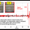
As a first test we ran the train over the same section of track twice in the lab when pulled by a locomotive at 5 SMPH.  In the first pass the track was normal, while in the second pass a gap of 1mm was intentionally created to show the sensitivity of the sensor. As seen in the data the MEMs sensor captures the vibration with a large force vector magnitude as the wheel truck encounters the discontinuity, and the oscillations as the train resumes its rest position is also visible.

------------------------------------------------------------------------------------

          Trial Run on the Layout

------------------------------------------------------------------------------------

ACC_test2

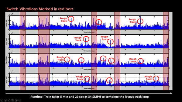
Finally we ran the telemetry train around the club layout (takes 5 min and 29 seconds per pass) and collected 4 sets of data over 4 passes. This data was collected at a much higher speed of 34 SMPH, (I plan to investigate the effect of speed on the system sensitivity later on). Of course a large layout has vibration and bumps from track switches, so the first step was to mark those onto the captured data traces. The remaining peaks in force magnitude are then investigated physically (time correlates to train position in the layout). What we do is take a photo of where the train is at 0,30s,60s,... and use that to know what section of the layout the data corresponds to. We then evaluate kinks or other discontinuities in the rails and make repairs as necessary.


Overall it's a pretty elegant way to manage a large layout. One of the next steps I want to look at is having multiple telemetry trains coordinate to reduce the acquisition time at slow speeds through large layouts. This is mostly just more DSP work to correlate end-points and stitch the data.


Anyways hope someone finds this interesting!


Adrian J Tang

(www.sadcircuitdesigner.com)


Attachments

Images (4)
  • ACC_system
  • ACC_assembly
  • ACC_test1
  • ACC_test2
Last edited by Adrian!
Original Post

Replies sorted oldest to newest

Hey there! .... I actually did think about some kind of indicator or something when the the force (or even 1 of its components) goes over a threshold. There are 2 issues though

1. We don't do the filtering online, we are doing it after. That means the raw data would have to be used which is noisy (since we haven't smoothed it yet) so the light would flash a lot.

2. Loop speed

Right now we have a loop like the top one. If you add the conditional for a light or something else you loose loop performance pretty quickly. Some of the vibration events are like a 20th of a second (50ms) so if you sample too slow you might start missing them!


code

Another one to try would be using a webcam running a totally different software thread taking still pictures at maybe 4-5 Hz then time-stamping them. Then just link the time index in the result to the given picture with the same index.  I guess you would want the webcam pointed out the back... I need to think about that a bit

Attachments

Images (1)
  • code

That is very cool, and not too terribly different from what is done in the real world to acquire load data for mechanical simulation testing. 

I notice the accel is mounted in what appears to be a slight angle though. I know the ones I work work with have to be aligned with the intended measurement axis. 

It would be cool to set up a wheel encoder to correlate distance with the recorded events.

Norm Charbonneau posted:

That is very cool, and not too terribly different from what is done in the real world to acquire load data for mechanical simulation testing. 

I notice the accel is mounted in what appears to be a slight angle though. I know the ones I work work with have to be aligned with the intended measurement axis. 

It would be cool to set up a wheel encoder to correlate distance with the recorded events.

Yeah wheel counter. So professionally I'm a chip designer and generally not very mechanically-adept so the wheel counter didn't work out so well for me (or the train). I hope someone better than me tries that though!

Good catch on the accel angle. I mounted it the way it fits best. It creates a DC offset in the signal due to gravity when is isn't mounted normal, but since I turn it into total magnitude (X^2+Y^2+Z^2) in the end the orientation is lost in the end of the processing anyways. I thought about analyzing the track as X,Y,Z components... but its less intuitive and in the case of a bump, only 1 axis is dominant anyways.


~Adrian


Stoshu posted:

What a great way for troubleshooting. Have you tested this on different track types ? IE fast track , gargraves , ect ?


I tried it on the fast-snap-track and tube-track in my lab, and I think the club layout we ran it over has a mixture of tracks, some flex and some others. Since it's basically detecting when the train shudders I think it won't matter too too much about the track structure itself. We will certainly try it though to make sure.


Adriatic posted:

   It would be interesting to see that info compared directly to a sound wave analysis of the same run.

Talk about paying attention to track work

thanks for sharing.

Sound is an interesting thought for sure. My first instinct is the train is kind of an ambient noisy environment. Normally I'd say we could just put an equalizer to push down that background noise, but the bumps are going to be very broadband sounds (making them hard to filter selectively).  Regular vibrations may cause issues, I dunno, maybe a FEM simulation would tell something. 

I like the idea. It's probably quicker to build than to simulate. I'll put it on the project list for 2017. An electret mic on the wheel truck, an audio amp (maybe an LM386 or something similar). The captured data file (I guess native wave) is going to be big 44KHz X a 16 bit sound X 5min around the layout... so the software needs some thinking to handle cleanly.

Anyways interesting idea!

~Adrian


Norm Charbonneau posted:

Well if you record the raw accelerations from the x, y, and z axes, you could also see things like twist and yaw by calculation. This may help catch gauge issues and other anomalies like dips and sags. Are you using a fixed mass to calculate forces then? This is so cool man!

Yeah we measured the weight of the trucks directly and did some ansys simulations to figure out the approximate dampening factor from the car body above.

I think the biggest limitation is the sample rate. The 60 Hz is a bit mediocre for measuring motion but we're constrained since it needs to like... fit in the train.  Most of the recorded bumps are only 1-2 samples long so the data is pretty sparce and it's hard to make sense or classify signals as this or that type of issue....

The issue with higher sampling is there are only two types of commerical ADCs out there:

1. Simple ADCs that you read directly from your code. These don't have a time limit but their sample rate is really limited since it's a for loop or something running on the computer. This can cover the time of the train on the layout loop but the sample rate is tragically low.

2. FiFO strobed ADCs that quickly capture a few 1000 points at high speed then return them to the computer at low speed. This has the sample rate and bandwidth to capture at KHz rates, but only for a few seconds so it can't even come close to covering a whole layout (or even a 10 ft section of track)

I guess we could like have the ADC stream the ACCs to an SRAM, but then there needs to be an FPGA with a memory controller and a USB controller to download them after. That's at the high end on cost, complexity and design work... but technical constraints aside... if we could sample at 1 KHz or something similar so the raw accelerations were smooth functions instead of just spikes in the waveform.... I bet all those things you mentioned are possible to compute!


Adrian,

Any real world conclusions? What was the cause of the anomalies? layout expansion and contraction, track expansion and contraction, roadbed shrinkage or movement, physical abuse or installation variances?

I use a finger during installation, but I have no way to monitor post installation issues.

I am wondering if there's a common reason that seems to be found when someone repairs the area.

The NJ Hi-Railers layout may benefit from a system like yours. They have a huge, high run time layout also.

Moonman posted:

Adrian,

Any real world conclusions? What was the cause of the anomalies? layout expansion and contraction, track expansion and contraction, roadbed shrinkage or movement, physical abuse or installation variances?

I use a finger during installation, but I have no way to monitor post installation issues.

I am wondering if there's a common reason that seems to be found when someone repairs the area.

The NJ Hi-Railers layout may benefit from a system like yours. They have a huge, high run time layout also.

Uh, I'm super not-mechanically inclined so I'm not too sure what the root causes would be. From our clubs layout and the limited testing done so far, it seems most of the issues are on curve joints areas.

The telemetry train is a work in progress so we're going to keep improving it (Lots of good suggestions to look at in this post already). Right now we just posted it to share the idea with others and have an interesting discussion (feedback makes it better of course!)

At some point when we think it's "good enough" for everyone to use without being a DSP expert, I plan to put up the bill-of-materials, assembly diagrams and code so everyone can make one. Right now we're still changing code almost every run and learning a lot about how to run it and where to run it, so I don't think it's ready for release.

Add Reply

Post

OGR Publishing, Inc., 1310 Eastside Centre Ct, Suite 6, Mountain Home, AR 72653
800-980-OGRR (6477)
www.ogaugerr.com

×
×
×
×
Link copied to your clipboard.
×
×