
With 300 feet of mainline, finding an inexpensive way of fabricating catenary led me to experimenting with common materials.  The methods of construction, while economical, produces a sturdy assembly after a few sections are completed.  You won't find many exact measurements in this instruction, only enough of them to make rough duplicates of sub assemblies.  Unless you have long mainline straights, the dimensions will need to be tweeked to suit a tunnel, bridge, curve or switch.  Because of this, you could say I'm building this by eye rather than from drawings.  Having the ability to envision the finished product installed sure helps here.  Any questions, hints or tips are really welcome, since I'm flying solo.

Materials:

1) Mild steel TIG rod, 1/16" X 36".  The copper coating on this type welding rod also makes it ideal for soldering....and you will be doing a lot of soldering.  The rod will bend but is brittle enough to break on the second or third bend.  Cutting is done with side cutters, scoring the rod with a slight squeeze, then bend to create a clean break.   This is the type rod I have access to...1 pound, or 34 rods cost $10.00.  Well equipped automotive stores should offer a similar brand.

2) 1/4" hardwood dowels.  Found some measuring 12" long at a dollar store. These are surprisingly sturdy enough that once connected together by the rods, a really solid assembly is produced. 

3)  Solder.  Use a rosin core type...you can avoid coating with flux by using rosin core.  I just happen to have a supply of 53/47 that works quickly and creates a robust bond.

Tools:

1) Wire snips/ side cutters.

2) 3', 2X4 for a jig.......I used cedar...smells good when burning under the soldering iron.

3) Soldering iron or gun

4) Favorite drill with a 1/4" and 1/16" bits.

5) Metal clamps or small vise grips.

6) no fear

Sub assemblies.

Survey the layout to figure out where best to begin.  Preferably on a straight section of track, without surrounding features to interfere, while you get your construction feet wet.  Decide the width need to span your track and drill 1/4" holes in your benchwork where the first 2 dowels will go.

At the bench, I take the 2X4 and transferring the width measurement, drill 2 holes, say, 11" apart.  Line up 2 dowels, measure and drill 2 holes through each dowel, approximately the height of the cross bars between the poles.  I choose one crossbar measurement for the entire layout ( 1 1/2" down from the dowel tops )...that way the tops of all the poles crossbars line up once installed.  Drill 1/16 holes about 1" into each pole top.  Insert the bottom of the poles into the 2 holes in your 2X4 jig.

Fashion 2 crossbars from the rod, roughly 11 1/2", insert through the dowels and bend at the ends.  Forming an M shape from another length of rod ( these take a bit of skill ), insert the ends into the dowel tops.  Ideally, the V just touches the top crossbar but overlapping is OK too. 

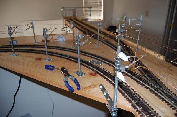
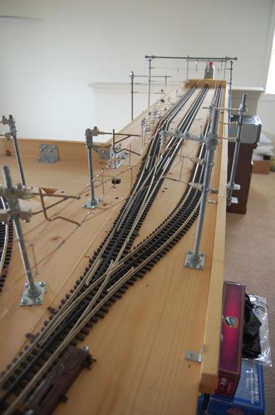
Here's where you begin to solidify things up by soldering the crossbar tips together and the V bottom to the crossbar.  I don't glue anything on these upright assemblies.  Between the 2 crossbars I bridge the gap at a few places by dropping in a short piece of rod between the two and soldering all 3 together.  All that remains is to drill and install angled bracing, soldering the top end of the braces to the bottom crossbar.  The photos should help guide you better than any description.

The end result in the jig.....more on the jig next time

Those little metal clamps keep things aligned when a 3rd or 4th hand is inevitably needed while soldering.  You'll appreciate how easy it is to solder this material, with the rigidity to avoid accidental warping or bending as with softer metals.  That ability to keep it's shape really assists in producing a trolley wire that doesn't deflect under a spring loaded pantograph.  No need to build in tension to the trolley wire to keep it taught.  Another benefit is the rod conducts heat poorly.  Many times I found I was holding the rod an inch away from what I was soldering, and no burnt pinkies.  We'll get to making the trolley wire stringers next.

Bruce


Last edited by brwebster
Original Post

Replies sorted oldest to newest

The 36" rod comes with flattened 1" sections near both ends, which I worked to my advantage.  The first step was to bend the rod at either end of the flat surface, forming U shaped ends as seen here.  This produces a trolley wire length of approximately 32".  Once formed, a rudimentary jig on the 2X4 is produced by simply adding a screw at each top corner. 

Take 2 more rods and cut off the flat section from each end.  The first is placed parallel to the trolley wire with short spacers in between, then solder in place, much the same construction as the crossbars.  Five equally spaced spacers seem sufficient to avoid deformation from pan pressure.  The dark blue lines drawn on the jig, guide the positioning of the spacers.

Solder the spacers and ends into one assembly. 

And finally, place the 3rd rod parallel to the upper rod and solder it at center, above the middle spacer.   Position the 3rd rod end over top of the short angled rod above each screw.  Bend the short angled rod to match the curve of the 3rd rod and solder in place.  A small upright brace at each end adds strength...you could add as many as you like here.  And there you have it, your first stringer.

You'll find the speed of assembly increases with a little practice and repetition .  Here's the perfect way to improve your soldering skills too.  Although every stringer on the layout won't be the same length, I made enough of these standard sized ones to suffice for now. Note that no 2 stringers are exactly alike, but the discrepancies are allowed for in the final assembly.

  Making hangers for the stringers is probably the most precise step of all.  Luckily they are small and easy to make.  Til next time.

Bruce


Dan Padova posted:

Great start Bruce.  I hadn't thought of using the TIG rod.  I am currently using 1/16" diameter brass rod.  Looking forward to your progress.  Mine is on hold at the moment.  

Thanks Dan,

I experimented with brass wire off a spool.....turned into a giant curly mess.  Rod is the way to go.

I was concerned about sagging at the center of each stringer, especially with my extra long spans and no tensioning.  Soldering out of sequence produced a stringer that actually bowed up in the middle.  Still learning as I go.

Bruce

MaxSouthOz posted:

Nice thread, Bruce. 

I like watching your engineering mind at work.

Thanks Max,

It's not neat or precise like store bought cat, but then, producing something economic and more realistic without the use of flimsy materials was the goal.  With about 15 feet already installed, I'm having good results with all my electrics so far. Many details still need ironing out, only adding to my enthusiasm about the project. 

Bruce

Bruce, you may have mentioned what type of soldering tool you are using, but Ill ask anyway.  From one of your photos it looks like an ordinary soldering iron.  I've been using a butane torch with good results.  I wonder if a resistance solderer might do better.  I've been toying with buying one.  

Dan,

At the bench I use a Weller soldering station with adjustable temp.  On the layout, a soldering gun suffices.  Even though the steel is a poor conductor of heat, the copper coating allows for quick, positive solder joints with no special treatment.  I have had to bend the assemblies, and none too delicately, to follow the contour of the track, without busting a single solder joint.........yet.

Bruce


Last edited by brwebster

Good evening all:

Bruce, very nice work and excellent instructions.  I'd also be curious how you go about powering your system (or plan to) and which motors you have.

Before I post the following, I wanted to say that it is not my intent diminish anyone's work with my own.  Seeing Bruce's system excited me enough to want to share a piece of my own, and add that there is another nutcase O modeler in the world that loves designing and building working catenary systems.

I'd like to humbly submit that using copper wire can work, and can be quite enjoyable if you're into such challenges.  I am building a small system where the wire structure and catenary supports are modeled after Amtrak's Euro style above New Haven.  The cat poles and support structure uses common hardware and are not really 'modeled'.  The point is to create a realistic and heavy duty system to run electrics and perform some operations.

I use brass rod from Lowe's for the cat supports, and 18g copper wire for the messenger and trolley wire.  The wire is under fairly high tension, which is adjustable and secured at various 'pull-off points' around the system.  DCS controls the system through a custom switch-board.  There are 5 isolated overhead circuits.  A stripped Atlas AEM7 is the test vehicle, (see LEDs on the roof).  AEM7s, MUs and a TRAXX F140 are the intended users

Bruce -- Thanks for sharing your work and ideas.  Its really fun to see different designs and follow what others are doing.  I'm eager to see how your system progresses.


--NMM

Attachments

Images (2)
  • WEST
  • EAST

Hi Dan:

Thank you.  The track plan is somewhere around 75ft +/-, enough that, like Bruce, the materials need to be inexpensive and locally acquired.  Everything but the wire is from Lowe's or HD, including the 3/8-24 threaded rod you correctly noted.  The 125ft 18g copper spool is from SmallParts.  All of the cat support masts are bolted to the table over a metal plate.  Otherwise the wire tensioning would bend the supports into the benchwork.  Some days progress was '3 steps forward, 2.9 steps fixing things you should have foreseen.'  I'm typically not inclined to share projects until they are more operational, but after Bruce's post I couldn't help myself.


Attachments

Images (2)
  • mceclip4
  • mceclip5
Last edited by Pantenary
Pantenary posted:

Hi Dan:

Thank you.  The track plan is somewhere around 75ft +/-, enough that, like Bruce, the materials need to be inexpensive and locally acquired.  Everything but the wire is from Lowe's or HD, including the 3/8-24 threaded rod you correctly noted.  The 125ft 18g copper spool is from SmallParts.  All of the cat support masts are bolted to the table over a metal plate.  Otherwise the wire tensioning would bend the supports into the benchwork.  Some days progress was '3 steps forward, 2.9 steps fixing things you should have foreseen.'  I'm typically not inclined to share projects until they are more operational, but after Bruce's post I couldn't help myself.


Thank you for posting your catenary project, also. Yours is yet another good solution to the task of overhead wiring.

"I'm typically not inclined to share projects until they are more operational, but after Bruce's post I couldn't help myself."....PANTENARY

I'm glad you did share your work during it's construction.  Doing so enables others to gain more insight into your methods.  Pictures, as they say, are worth a thousand words.  

So, I'm curious about the attachment of the standoffs to the masts.  Do you think you can post a close up photo of the connection ?

Last edited by Former Member

Add Reply

Post

OGR Publishing, Inc., 1310 Eastside Centre Ct, Suite 6, Mountain Home, AR 72653
800-980-OGRR (6477)
www.ogaugerr.com

×
×
×
×
Link copied to your clipboard.
×
×