I was running my LionChief Plus GP7 the other day and suddenly the fuse popped. I looked for derailed wheels, objects shorting out on the track, I even took the cover off to see if there was something shorting out there, but every time I replaced the fuse and applied power it popped. My transformer is a PW ZW so I use fuses (luckily).

I called a Lionel tech friend and he met up with me at the club. He took the cover off and put it on the track and applied power and smoke started coming off the circuit board. Since it's still under warranty he said so fixing it is no problem. The cool part is he loaned me his Lionel FM Trainmaster with TMCC since I just got a CAB-1L/Base-1L unit which I bought to run my Weaver U25B that has a ERR command and Railsounds boards. I was not expecting him to do that. Still going to miss my LCP.

Last edited by DennyM
Original Post

Replies sorted oldest to newest

Denny,

   Moonman (Carl) is absolutely correct if you exceed the 18V especially with your older Transformers, you can damage your LC & LC+ engines, the instructions point this out clearly.  Its one of the reasons I have my old ZW set at 16.5V and use and off on switch to control it.  You might consider doing the same thing, when your engine comes home to your layout.

PCRR/Dave

Last edited by Pine Creek Railroad
Pine Creek Railroad posted:

Denny,

   Moonman (Carl) is absolutely correct if you exceed the 18V especially with your older Transformers, you can damage your LC & LC+ engines, the instructions point this out clearly.  Its one of the reasons I have my old ZW set at 16.5V and use and off on switch to control it.  You might consider doing the same thing, when your engine comes home to your layout.

PCRR/Dave

Good point.  I must have missed that when I read the instructions for my SW1500.  And the on/off switch for that particular post on your ZW is a good idea.  

Denny,

   I use the on/off switch on the entire ZW Transformer main power line, and simply set & leave the handles on the ZW at 16.5V that control the channels going to the tracks, where I run my LC/LC+ Engines.  In this manner nobody can direct more voltage into the tracks, than these particular engines can handle.  The actual Engine controls are of course run from the individual LC/LC+ hand held RC.

PCRR/Dave

Last edited by Pine Creek Railroad

So you can run the LC+ at 16.5V? I have been running it at 18V. I check it with a volt meter to make sure it isn't more than that. The goods new is I'm picking up a ZW-C with the two bricks and trading my PW-ZW in. I am going to follow your advice though and keep it a 16.5V or does that matter with the ZW-C?

LC+ will run at anything over 8VAC, however the max speed will be limited by how much of a load you are pulling.  Just the engine?  9 VAC will give you full speed.  Add a couple cars and you may need 11-12 vac.  through testing I've found that even pulling a very heavy load, 12 VAC is enough to provide the full range of speeds.  The smoke unit is then the limiting factor, as it does not really work below 14 volts and needs 16 volts to put out full output when the engine is run by remote.  For some reason when run conventional the smoke unit works with about 2 volts less on the track.  End result, if you're not sure how much voltage is on the track, error on the side of caution and turn it up only enough to give you the range of speed you desire, and the volume of smoke output you like.  16-17 volts is plenty.  

JGL

Edit:  I missed the part about the ZW-C.  The ZW-C doesn't  control actual voltage the way a traditional transformer does, so from a technical stand point, the engine can see 'full power' even when the throttle is set to a lower level.  With the PH180 bricks, however, you should be fine at full voltage, and the ZW-C is likely to drop the voltage by about 0.6 volts anyway, so full throttle will be fine.  lower voltage will probably also be fine, though I've not done any tests with a 'chopped wave' transformer to confirm this.  

Last edited by JohnGaltLine
JohnGaltLine posted:

The ZW-C doesn't  control actual voltage the way a traditional transformer does, so from a technical stand point, the engine can see 'full power' even when the throttle is set to a lower level.  With the PH180 bricks, however, you should be fine at full voltage, and the ZW-C is likely to drop the voltage by about 0.6 volts anyway, so full throttle will be fine.  lower voltage will probably also be fine, though I've not done any tests with a 'chopped wave' transformer to confirm this.  

I'm not sure I understand this statement.  The ZW-C output cannot exceed the settings of the handles.

The ZW-C can put out full voltage peaks at low RMS voltage settings. This is because it adjusts the RMS voltage by turning on the  output at a varying time in the sine wave. There are lower voltage settings with full voltage peaks therefore. In JohnGaltLine's comment, replace the words "full power" with "full voltage".  Like the CW80. Does that answer the question is here?

MartyE, 

I suppose I was trying to keep it simple, but CJack has the meat of it.  in a pure sine wave you can determine the peak voltage of the output by multiplying by 1.4141, which gives you about 25.5v peak off an 18v RMS voltage, or about 20v peak off 12v RMS.  With a "chopped" wave (pulse-width modulated waveform)  the peak voltage can be much higher than one would expect when the output is set to lower levels.  At anywhere above 25% duty-cycle, (Throttle more than 1/4 way up) the peak voltage of the output will be the same as that at full throttle.  Now this should be a non-issue for the ZW-C and for lionchief, as the PH bricks, from what I understand put out a voltage not much over 18VAC RMS.  The Triacs in the ZW-C will also drop the voltage by about 0.6 volts, as most silicone components tend to do.  I see no reason for there to be any problem with using ZW-C and PH180 to power LC/+.   on the other hand there are some other 'chopped wave' transformers out there that use power bricks that put out 22-24VAC RMS, and if it is true that more than 18vAC RMS can damage LC/+, I would avoid these other transformers, as even at lowered throttle so that the track is at 18VAC RMS, the peak voltage from a 22v brick could be say 31v.  I would expect the warning is because there is some component in the LC/+ electronics that can be damaged by peak voltages much over 25.

JGL

WB47,

   The instructions on the Lionel LC & LC+ say not to exceed 18V, I try to keep the voltage down under 18V a little to safe guard the engine electronics.  Your 180 Bricks should be fine at a Constant 18V, if the Brick delivers a constant 18V for real.  However you are pushing the envelope with max voltage for the engine.  As JGL points out in his post I keep the voltage for running these engines between 16.5 - 17.0 and they run perfectly on both my FasTrack & my RealTrax Loops.

PCRR/Dave

DSCN1671

Attachments

Images (1)
  • DSCN1671
Last edited by Pine Creek Railroad

Power on a MTH • TMCC • LionChief Plus Layout & Conventional Operations. 

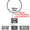
This is how I manage 4 Lionel, 180 Watt Powerhouse Bricks on my layout. It is impossible to get 18.0 Volts to your rails with a 180 Watt Lionel Brick.  The only way you could get 18.0 Volts to the track, would be to cut off the mail plugs on the Lionel Brick and run the wire directly to the track. If you cut off the male plugs, this will void the Lionel Warranty. According to Lionel, these Lionel Power House Bricks must be plugged into a ZW.

I use tubular track and each main line has about 100 feet of track, for a total of 400 feet. 

How the power gets to the rails on my layout. from the starting point.

1.  Starts at the homes power panel in the train room. Leaves on a dedicated 15 amp circuit. This line is also GFI. The panel also has a whole house surge protector.

2.  Enters the layouts control panel and enters a Kill Lighted Switch.

3.  Than the power goes to a junction box with 4 plugs, the outlet than breaks out into 4 power Surge / Arrest Protectors. Everything on the layout is plug into these strips with space left over.

4.  The power now enters 4 Lionel 180 Watt Powerhouse Bricks, on the end of each Lionel Brick is a male plug.  These 4 male plugs are plug into the back of a Lionel ZW Transformer.

5.  The power leaves the ZW on 14 Gauge Stranded Wire. Next it goes to the MTH / TIU.  There are 4 throttles - Left to right on the ZW - Track 4 / Track 3 / Track 2 / Track 1.

6.  The wire is attached to the Track Interface Unit on the Input Side with, Klein / Ideal Terminal Connectors. Track 4 to =  Fixed Voltage,  Track 3 to = Variable Voltage,   Track 2 to =  Variable Voltage, Track 1 to =  Fixed Voltage. This means that the large throttles on the ZW are fixed and the small inter throttles on the ZW are variable voltage.

7.  The power leaves the Track Interface Unit on the Out Put side and goes to several MTH 50-10-1020 24-Port Terminal Blocks, This block sends the current to the layout control panel that sends the power to the tracks and sidings, using single pole, single throw switches.

8 - Each main line has 3 blocks so I can run conventional locos, using the throttles on on the Lionel ZW. Old school operations. The 14 gauge wire is solder to the track about every 6 feet to the inside of the rails.

9 - The Lionel TMCC is wired to the TIU with a MTH cable 50-1032 and a 14 gauge ground wire.

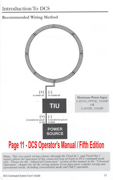
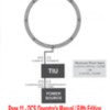
Below are two wiring diagrams (1) My Layout (2) Wiring diagram from the MTH • DCS Operator's Manual, Fifth Edition, Page 11. Note: I also use the "OGR Video Guide, Digital Command System".

Any questions or a suggestions for a do over. Gary   /   (Click on diagrams to enlarge).
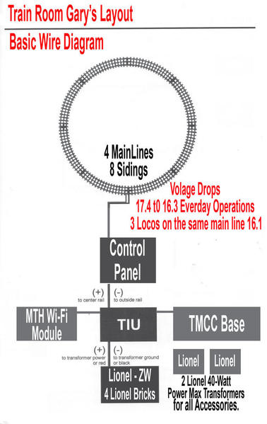
Wireing Diagram Train Room Gary's Layout Voltage DropsWireing Diagram Page 11 DCS Operators ManualCheers from Train Room Gary Pan 2 View

Attachments

Images (3)
  • Wireing Diagram Train Room Gary's Layout Voltage Drops
  • Wireing Diagram Page 11 DCS Operators Manual
  • Cheers from Train Room Gary Pan 2 View

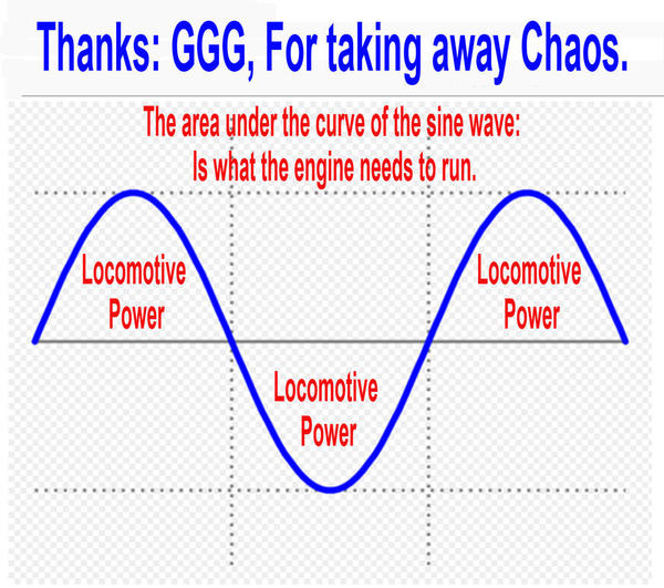
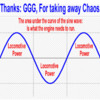
You guys do a good job of confusing the issue.  The engine doesn't look to run on just the peak.  The Lionel limit is based on the 18VAC output of the transformer.  The RMS value.  Not a peak value.  So don't confuse stuff and stick to a standard for understanding.  The area under the curve of the sine wave is what the engine needs to run.

The ZW-C takes a full sine wave input at 18VAC from the Power House Brick.  The ZW-C Controller uses electronic control to vary that voltage.  Just like a Power Master would.  It also depends on handle position (throttle pot) though.  So even with 18VAC coming in and command mode being used, if the throttle is set to 12VAC setting, the output will only be that high regardless of how many times you spin the Cab-1 throttle.  It is a good method for letting children run trains, or when trouble shooting and you do not want to loose control of the engine at full voltage/full speed.

Any Lionel transformer will work with LC/LC+.  You might run into issues with an older PW transformer especially ones that can output in the 22-24VAC (RMS) range.   G


GGG posted:

You guys do a good job of confusing the issue.  The engine doesn't look to run on just the peak.  The Lionel limit is based on the 18VAC output of the transformer.  The RMS value.  Not a peak value.  So don't confuse stuff and stick to a standard for understanding.  The area under the curve of the sine wave is what the engine needs to run

Hi GGG

Sine Wave

but, as a model railroader, (End User). All I need to be concerned about is Voltage, Voltage Drop and Electrical Continuity.   I have an electrical instrument that can measure all of these.  No way to measure the sine wave at this time.  So I will check the Voltage,  Voltage Drop and Electrical Continuity. This process should stop all the confusing issues.

Gary

Attachments

Images (1)
  • Sine Wave

I agree that the topic has gotten confused at this point, and moved wholly away from the original issue of the topic.  Still the information is good for folks interested in theory, and why an 18 volt limit might have been set.  The point I was trying to make is only that when a controller that uses PWM, a so called chopped wave transformer, is used, the voltage seen by components will be the maximum peak voltage of that transformer, not whatever lower level the throttle may be set to.  

This is just theory based on my best guess of how LC/+ works, as I have not reverse engineered any of the boards in the engines yet, however I can't think of any better way to accomplish the task:  Because LC/+ will work equally well on both AC or DC power I have to assume the first thing that happens is that incoming power is passed through a rectifier, then through a voltage regulator of some sort.  I imagine it is also possible that power to the motors is run directly from track to motors through a MOSFET H-Bridge.  So in all, the rectifier bridge/diodes, filter capacitor, voltage regulator, and MOSFETs all need to handle the incoming peak voltage.  The RMS value is meaningless in selecting these parts as any of them will be damaged by peaks of over voltage only milliseconds long and do not care about average voltage over time.  I can likely rule out the bridge/diode rectifier, as these are typically good for at least 100 volts.  The filter capacitor is a little suspect, as if it is rated for 25 volts, that puts it right on the edge of safe running under 18vac rms (remember the .6 volt drop from each diode of the silicone rectifier).  I would hope, however that big L was smart enough to use a 30+ volt cap here.  Next we have the regulator, most linear regulators are good for 35vdc input, however, this I think is the weak link.  the higher the input voltage, the more heat a linear regulator will make, and my theory is that over the 25.5VDC produced from 18VAC RMS the regulator does not have enough cooling and will be damaged over time.  There could also be some low voltage limit on the MOSFETs, though I've found that these tend to be good for at least 60V, so doubt that is the problem.  

A second point of consideration is the sensing mechanism used for conventional control.  here track voltage is read by the microprocessor and used to determine what speed the engine will move.  It is possible that whatever circuitry is used to relay track voltage can be damaged by excessive voltage.  If it is something as simple as a voltage divider, excessive voltage may even damage the microprocessor.  I lean more toward the regulator being the limiting factor, however, as a simple zener diode shunt would protect the processor from over-voltage input.  

So what we have here is simply that with a chopped waveform going into a filtered DC supply, the output of that supply will be the peak to peak voltage of the input.  25.5VDC (actually 24.3v) from 18 VAC... but 31VDC (29.8) off a 22VAC source, even if the RMS is set lower.  If anywhere in the above mentioned 4 parts one of them doesn't like more than 25 volts, running your engine on more than  26.2 volts peak to peak will cause problems.  

Honestly, however, I think Big L would have been smart enough to just slightly over-design the circuit, and use components rated for at least 30 volts, making them safe on   a pure wave input supply up to 21 VAC RMS.  I suspect that stating only to use 18VAC serves two purposes; first to leave a bit of buffer room and second, to sell their brand of transformer, as the major competing brand outputs a higher voltage.  

Anyway, point is that it is peak to peak voltage that matters for component limitations, not RMS.  

JGL

Are you sure?  I thought with FETs the algorithm chosen controls what voltage wave form is outputted.  A Fet can turn on as the AC wave form comes off the Zero amplitude and be clipped at 10VAC, and turned back on coming down at another value.  Or it can be turned on and off at a very high frequency but still be designed to stay off at high amplitudes.  So everything is just an assumption on your part.  There are plenty of post on theory that folks can go read in the electrical section.  I still think much of what is being stated is just a red herring to original folks questions and creates real confusion on what is an acceptable transformer, or what voltages must I set to protect equipment, etc....

I have not put a PM or my ZW-C on a scope, but I do think others have.

Also confusing transformer input to a circuit board, and what that circuit board does in the motor drive section as an example can be two different processes.  MTH doesn't use an H Bridge.  It varies on PS Version, but they use a Relay and a single FET to control motor speed.  G

I traded my PW-ZW in for a ZW-C Yesterday for a really good price. Gary that was a Interesting post, but a bit much for me. I don't own MTH or DCS or intend to go WI-FI. I do like everyone's input. My tech friend is still waiting for Lionel to send him the replacement board for my LC+. Now I have to get use to the ZW-C. It is very different in how it operates from the post war ZW.


100_4324

Attachments

Images (1)
  • 100_4324
Last edited by DennyM

GGG, whatever level a FET may be set to output, they can still only take input voltages up to their maximum rating, which was the only point I was making.  Also this topic is specific to LionChief/Plus engines, other engines and control systems have different max voltage specs.   I expect I'll be dismantling a LC engine as time allows to figure out exactly what's going on in there, when I have the time.  

I'm content to just let this one drop as nothing is getting done, but I'd just like to be sure that I understand your position.  As I understand it you are saying that it makes no difference what type of transformer/controller is used, and it does not matter what the maximum output of that transformer/controller is, as long as the throttle is turned down such that the track receives no more than 18VAC true RMS.   Is this a fair summary of your position, GGG?  

JGL

I did not think you were talking about a specific FET rather stating regardless of throttle position the Peak of the input is always seen at the output of the transformer.  That is what I disagree with.

Most of these FETs are at least 80 to 100V rated if not 200, or 400V for TRIACs.  So the specific FET is usually not the limiting factor on the board design for max voltage.  Capacitors rated at 35V and other chips would most likely be limiting components.

As far as my position, Yes as long as Transformer output is limited to 18VAC RMS any peak voltage is accounted for in the design.  G

When I got back home I decided to see if my theory on the voltage being supplied to the engine's electronics from chopped wave transformers was correct.  As it turns out, it was.  I explain in detail HERE:

I've also been tracing out the boards in a LionChief engine, and while I'm not nearly done I've got enough of it mapped out to be very suspicious of the claim that more than 18 volts can damage them.  So far it looks like they should be able to handle up to 24VAC with out any problems.  Of course I recommend following the manufacturer's instructions, but to come full circle, I am in serious doubt that over-voltage caused damage to Denny's engine.  

JGL

Well I just talked to my Lionel tech friend. He is fixing my LionChief Plus GP7. I was having problems and he took the cover off and put it on the track and when he added power the board started smoking. It's still under warranty, but Lionel is giving him the run around. He hasn't heard back from them since before York. I hope this is not the case. I was going to buy the LC+ GP38 if they ever release it, but now I'm having second thoughts. Sad, I like LC+. He also told me that anther person brought their LC+ to him that has the same problem.

Last edited by DennyM
DennyM posted:

Well I just talked to my Lionel tech friend. He is fixing my LionChief Plus GP7. I was having problems and he took the cover off and put it on the track and when he added power the board started smoking. It's still under warranty, but Lionel is giving him the run around. He hasn't heard back from them since before York. I hope this is not the case. I was going to buy the LC+ GP38 if it they ever release it, but now I'm having second thoughts. Sad, I like LC+. He also told me that anther person brought their LC+ to him that has the same problem.

Hi Denny: Click here to learn more about this issue. Read all the questions and comments. 

I am also a big fan of LionChief Plus, have three on my layout. Do not give up, Lionel is aware of the issue with the GP7. From what I have read and friends have told me is that the GP7 is the only loco in the LionChief Plus Line with a major issue. Something to do with the dual motors and the gears in the trucks locking up. Can not say for sure because I do not have a GP7 on my layout. If your Tech. can get the parts, you should be in good shape. Keep us posted.

Thanks - Gary

Last edited by trainroomgary
PDDMI posted:

Denny...Is your tech guy located in SW Michigan? I currently have three of the LC+ locos and sure would like to have someone somewhat close for repair work if needed.

I think I read recently that Gary is now using someone in St Joe?

Yes he's in St. Joe, MI too. My email is on my profile page if you want his number.

Last edited by DennyM

Well I was too quick to say my LC+ works great. Now there is a whole new set of problems. I can't express how angry I am right now. I am done with LionChief Plus (sorry Trainroomgary). I'm going to get my money back and it will be the last time I buy LionChief Plus. At this point I'm done with anything new by Lionel.

DennyM posted:

Well I was too quick to say my LC+ works great. Now there is a whole new set of problems. I can't express how angry I am right now. I am done with LionChief Plus (sorry Trainroomgary). I'm going to get my money back and it will be the last time I buy LionChief Plus. At this point I'm done with anything new by Lionel.

Got it................. 

Gary

Okay, I've simmered down a bit. After talking to some of the members of the local club I belong to, they have convinced me to give LionChief Plus another chance. I'm still getting my money back for the LC+ GP7 because it's not worth keeping with all the problems I'm having with it. I'm still not happy with Lionel. I feel like they don't care or they are hiring incompetent people.

"I'm still not happy with Lionel. I feel like they don't care or they are hiring incompetent people."

Don't you think judging an entire company and dozens of people based upon one lemon of a product is a bit harsh?

Don't get me wrong, one really, really bad experience can sour one on a person, an institution, a country.  But

statistically speaking, a product that doesn't work is just a product that doesn't work.  For every LC+ that is a lemon

there are probably a hundred that work well.  For every repair that fails, there are probably a hundred that turn out

fine.  You were almost certainly the  victim of bad luck (a stochastic process--immutable and unpredictable), not a company's failure or people's incompetence.

Good post. Actually it works for a lot of bad luck that's easy to blame like a manufacturer. I have those feelings and sometimes write a detailed email or post and then not send it. That does good without the wish I didn't say that so harsh...although some harshness like when the wheels fall out of your Berkshire when you take it out of the box, actually feels ok .

"Did you forget IMO?  Hard to imagine you know that to be a fact."

Who else's opinion would it be

I wrote "almost certainly" leaving room for the 1-5% possibility that malevolent aliens had taken over his Lion Chief + loco or that  evil or incompetent employees were now regularly employed in design/production/repair at Lionel.

I like the odds I'm right on this. 

I know of dozens of seamlessly functioning LC+ locos, including four of my own, and a hobby shop that has sold hundreds more with very few failures.

Add Reply

Post

OGR Publishing, Inc., 1310 Eastside Centre Ct, Suite 6, Mountain Home, AR 72653
800-980-OGRR (6477)
www.ogaugerr.com

×
×
×
×
Link copied to your clipboard.
×
×