Working on an MTH 30-1116-1 (20-1117LP). After completing the PS 3 upgrade and testing, I have no heat on the resistors in the smoke unit. Fan puffs and runs normally, timed with drivers. I have 8.1 ohms across the resistors. I cut the traces on the board and soldered the resistors in parallel, as it shows in the instructions, specific to the Allegheny. I had a new, spare, engine wiring harness from another upgrade kit that I wired in hoping it was just an open in the connector or cable somewhere, but it still makes no heat. I tried tracing the wires back to the tender, I'm getting continuity from the red smoke unit connector to the brown wire in the 4 pin connector in the tender. I also have continuity on the green and grey wires in the 4 pin, from the fan. Is the brown wire the power for the resistors? If so, what voltage should I see on the 4 pin connector? Are there any other tests that I can try?
Replies sorted oldest to newest
You missed a few discussions about PS3 steam upgrade kit smoke heater and headlight power.
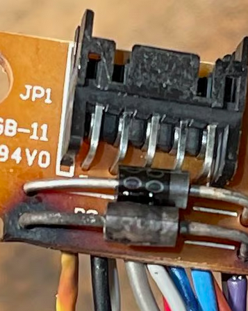
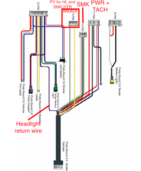
Key point- there are 2 diodes on the tether socket PCB that form the PV (Posiive Voltage ) via the the yellow or white main motor wires. In other words, because we are limited to 10 wires in the tether, MTH worked out a fact one of the 2 motors wires is always positive. The diodes then allow the headlight and smoke unit heater both to take advantage by using diodes rather than an 11th PV wire and bigger tether.
https://ogrforum.ogaugerr.com/...arness-pcb-w-2diodes

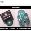
example failed diode
Your notes with replies in RED
I'm getting continuity from the red smoke unit connector to the brown wire in the 4 pin connector in the tender.
I also have continuity on the green and grey wires in the 4 pin, from the fan.Fan is on a different regulated DC source voltage.
Is the brown wire the power for the resistors? Yes, but it is the RETURN to the tender PCB on the negative side of the circuit. Also, frame ground and DC negative on the board are different things- important to know frame of reference when trying to measure a voltage.
f so, what voltage should I see on the 4 pin connector? Are there any other tests that I can try? Yes, ensure the white and yellow motor wiring plug at the PS3/2 stacker board is plugged in, ensure you have a headlight wired (blue connector) and it is working. If the headlight has PV and is working, then in theory the heater has PV and should be working.
I highly suggest you post a picture of your modified PS1 smoke unit. Many times folks make mistakes when cutting the traces and this can kill the expensive PS3/2 stacker board when you first power up.
Just imagine the potential number of blown up boards that happen(ed) world wide in total, rather than the installer(s) just buying a new smoke unit top PCB??????
Again, do you have headlight working powered off the blue connector in the PS3 steam upgrade harness? This is because it shares the same PV voltage source.
You also could temporarily for testing use another 6V bulb- example your reverse light bulb (from the upgrade kit) and plug that into the red heater plug- it would light showing heater status of working and on.
Have you ensured you flashed the correct steam large smoke unit chain files to the board?
https://mthtrains.com/sites/de...20DOCUMENT_FINAL.pdf
https://mthtrains.com/chainfiles
Upgrade manual https://mthtrains.com/sites/de...ction/50as10709i.pdf
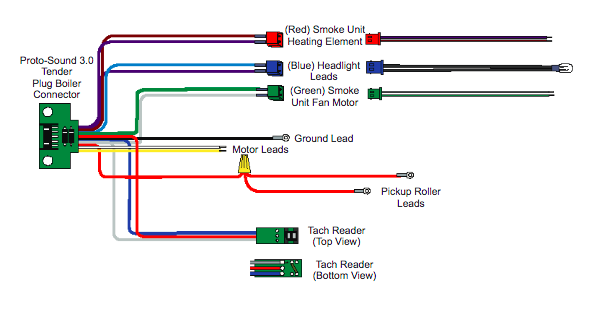
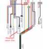
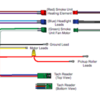
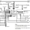
Diagrams below with some notes relevant to PV wiring for smoke heat.
Again, a 6V bulb can be used in place of the heater for visual indication during testing.
Attachments
I would read this topic because it too is basically about PS3/2 stacker and no heat.
@pennsy k4 posted:I'm getting continuity from the red smoke unit connector to the brown wire in the 4 pin connector in the tender.
I also have continuity on the green and grey wires in the 4 pin, from the fan.
Is the brown wire the power for the resistors?
If so, what voltage should I see on the 4 pin connector? Are there any other tests that I can try?
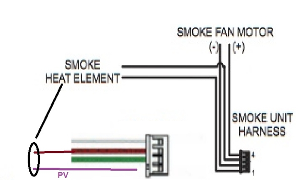
The 4 pin connector is for smoke, but 1 wire (PV) often a purple wire, is intentionally omitted because of the limitations of the 10 pin wiring harness, basically using the yellow and white motor wires with diodes at the engine side of the connection to then form PV inside the engine end of the harness.

Again, in this connector- grey and green are smoke fan.
Brown and the missing wire position are smoke heat, with the missing wire position being PV locally at the PS3/2 stacker board.
The pinouts we are looking for at the board are better explained in the PS2 diesel kit instructions- because PS3/2 stacker board set by name is replicating the functional wiring connectors and outputs of the PS2 boards. https://mthtrains.com/sites/de...ction/50as17540i.pdf
As you can see in the above diagram, the 4 pin smoke harness in a diesel directly connects to the smoke unit and PV for the smoke heater.
In Steam engine kits, PV in the engine is again coming from the white and yellow wires of the main motor section of the harness via 2 diodes found on the tether connection board.
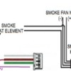
Gray Fan +
Brown Smoke Heat -
Green Fan -
Purple PV Smoke Heat +
Attachments
Did the smoke heater work prior to loading the correct PS32 chain file and the sound file for your Allegheny? Reason I ask is I've noticed a quirk with recently produced PS32 boards. Everything will work with the factory PS32 chain and sound files. After the correct PS32 chain file and sound files are loaded for the application the smoke heater stops working. The cure is a factory reset using a TIU. Once the reset is done power the board down, wait 10 seconds, power the board back up and add the locomotive back to the DCS remote. Everything then works correctly.
Thanks everyone for the quick replies and wealth of information. The headlight has worked properly the whole time. As Vernon suggested, I plugged in a back-up light bulb into the red plug in the engine, no light.
Just FYI- first PS3 upgrade kit was from last year, I installed it in a Rail King Northern (that had a bad PS1 board). After the upgrade, when I tested it, everything worked and it had generic steam sounds in it. When I put a sound file in from the last RK Northern MTH made with PS3, it worked on the first try. This time, while testing the Allegheny, I noticed it started with diesel sounds. The smoke unit fan worked but not the heat element. I installed the sound file from the last RK Allegheny they made with PS3, everything else worked, except the smoke unit heat.
I'll be honest, I've never heard of a stacker chain file before today. After reading the stacker board info from the link above, I downloaded "O Gauge Steam w/Standard Smoke" file and sent it to the engine. I shut everything down and then restarted. The light in the red plug came on immediately.
Now I have smoke!
Thanks again for all the help, Sean
“Thanks again for all the help, Sean“
Who is Sean? Vernon wrote a treatise, and Lou offered his thoughts.
I'm Sean. Force of habit, like putting a name in an email signature.


