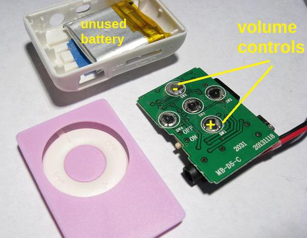
MP3 player battery?  The board I use has no battery.  Also, remember this is going to be something that hopefully gets produced in quantity, so any solution has to lend itself to easy assembly.


I'm currently rethinking my power supply situation, and I may have to revisit having two regulators and instead do a better job filtering the power supply for the more sensitive components from the MP3 player noise.  With a single supply, this issue gets a whole lot easier to deal with.


Here are two "new and improved" strawman concepts for the supercap approach.


grj 7v stepup

Adding about 15 cents in parts, above shows a switch that only charges the supercap when track voltage is present.  Unfortunately, this has and additional connection to the option board.  This has the higher filtered voltage to run a 2nd low-current 5V regulator.


grj 5v stepup

Per previous discussion of running the 5V stuff at something a bit lower, above uses a 5V fixed output stepup regulator that is actual a bit cheaper (and smaller) than the variable stepup module - 99 cents on eBay (221650839111).  In this case a 7805 on the option module performs the supercap charging duty and acts as its own charging on/off switch.  That is, if track voltage disappears, then charging voltage disappears.  Thus there are only 3 connections to the option board.  Since the charging "power" is occasional, I don't think elaborate heatsinking is needed.  More thrashing is needed to deal with the 2nd 5V regulator issue.


grj 5v stepup ebay module

Attachments

Images (3)
  • grj 5v stepup
  • grj 7v stepup
  • grj 5v stepup ebay module

I'm thinking that maybe the second 5V supply should go and instead I see if I can properly filter out the noise from the MP3 module feedback.  I'm going to bust out the 'scope again and see if that's possible.  I'm thinking of a low value resistor and large value cap for the feed to the secondary powered devices.  I'd also add a .1 ceramic cap for high frequency hash suppression.  Clearly, the secondary supply has greatly complicated the battery backup scenario, so maybe the way forward is to eliminate that as an issue.


In my testing, the single 560uf filter was plenty down to 7.5 DC out of the bridge at load, and I still got good transient protection.  I can use that board real estate saved for the second rather large cap for better filtering for the receiver and uP power supplies.  I'd also be eliminating the second regulator.


It's not going away, I'm just trying to catch up on some work I've been putting off.  I think I may redo the power supply to have a single feed and better filtering.  The dual supplies work well, but the complexity of the battery circuit is a problem.  Stan has sold me on the need to cover a wide audience, so I want to solve that issue.  Once I figure that out, I'll probably make a test board with the full up system and all the interfaces.  I do think about how the software is going to work, and I plan on working a bit on that in the background.


Hi John


I know it not going away but sometime times it good to walk away and come back with a fresh point of view. I know about the honey do list. I am on vacation this week and I have been try to get to my project all week and no joy. Family and the honey do list have taken up all my time, no complains but a fact of life. I believe that Stan is right but the wide audience but the issue as always is price of the final product. I would like to see how you solve the battery problem.  I am just using supercaps and cap to solve my problem on my project.  Software problem will be solve in due time as well. But the battery for this project is the sticking point. It has to work but at a reasonable price for production. I sure you and Stan will come up with a solution soon.


Thanks for the update.


I got the little step-up converters in, so I did a few bench tests.  The 2.5F supercap charged to 5V generates 12V of power for 7-8 seconds at 125ma, which is about what the input of the 5V switcher that powers the MP3 module draws at the full 250ma load.  It's at least practical to power the board from the supercap for the required amount of time, now I just have to come up with a power supply design that has a single voltage so the switchover is cleaner.  I like this way better than batteries.


One thing is it will take some time to charge the cap initially, I have to limit the current to around 300ma from the switcher as it's also powering the MP3 module and it only does 500ma max.


If I use a 22 ohm resistor in the charging circuit, the time constant to charge the 2.5F capacitor is 55 seconds.  I guess I can live with that, but it's fairly long, I figure probably a couple of minutes to get a decent charge of 85-90% on the cap.  If I connected a different regulator directly to track power, I might charge faster, but that's extra parts...


Decisions, decisions!


So to be clear, are you imagining this conventional option as a custom PC board to which the stepup module and a handful of components get soldered to...in which case some incremental components to speed charging time might be worth the trouble.  And are you OK with a 4-wire interconnect (though 3 is obviously preferable)?


In theory, if you had a constant current charger at, say, 250mA you could charge 2.5F to 5V in 50 seconds (i.e., 0.25A/2.5F = 0.1 Volts/sec).  So you could cut charging time in half or more - so I'm thinking some combo of constant-current switching to constant-voltage (plus resistor) which provides a better topping-off of the charge to overcome the caps internal DC resistance (not to be confused with ESR spec'd at 1 kHz). If you have your scope handy, what kind of DC step-voltage drop do you see when it starts discharging at 125mA?


Anyway, I'd have to think about a simple inexpensive circuit but perhaps something that uses constant-current until the cap voltage reaches X, then switches to constant-voltage (plus resistor).

Using constant current and then switching to voltage control seems a bit cumbersome, not to mention complex and more expensive.   With a 10 ohm resistor and a 7805T and the Schottky diode as you previously suggested seems to get me over 85% in the same 50 seconds, and it's dirt simple.  I could sky-wire that stuff and shrink wrap it, cheap and effective.


If I make it more complex, then I would look to make a PCB to connect the components, and then shrink-wrap it.  I have the feeling it'll run up the cost some, my only concern.   I'd obviously like to stick to as few wires as possible for the battery interface, but 4 wires isn't a deal breaker.


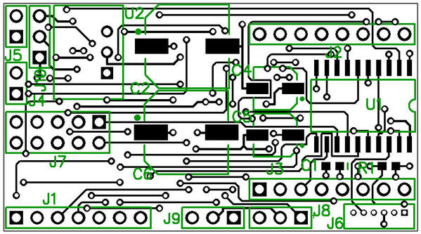
This is the latest trial layout, I'm trying to keep the connectors to commonly available spacing as well as easy to work with.  Most of them are .1" spacing, readily available and easy for folks to make up their own if necessary.  You can also buy .1" spacing jumper cables in a variety of pin counts very cheaply on eBay.  The 10 pin dual row one is for a 10 pin ribbon cable, I plan on supplying that with the board with a hunk of ribbon, probably about 6" long.  That allows you to easily use the optional outputs and inputs, and leave it off if you don't use them. 


RF-Link MP3 Interface, Rev. 3 Trial Layout

Attachments

Images (1)
  • RF-Link MP3 Interface, Rev. 3 Trial Layout

Looks like it's coming along great ,It's going to be a great asset to any layout. Do you have any idea how much you will sell them for and are u already going to have the sounds programed in or are you leaving that up to the customer!

Alan
what will the customer need if he or see want to add sounds or change them?


Alan

GREAT LAYOUT ON THE PC BOARD!!


The sounds will be pretty much up to the user.  I figure to have some "canned" sounds so it will do something when you get one, but I haven't settled on what they might be.


The cost analysis has to come after the final design is in, I don't know what I'll be dealing with until I know what the entire materials and fabrication will cost.  I'm thinking about keeping the build cost down, but that's not the major focus.  Right now I'm in "prototype" mode, I just want to sort out all the design issues so I have a clear path forward.


I tried Stan's solution for the battery power supply running the electronics at a lightly lower voltage using a Schottky diode, but there is a small issue with that.  The receiver frequency is voltage sensitive, and the drop in voltage changed the oscillator sufficiently to cause flaky reception.


I think the plan will be something like the second suggested option with a full five volts and running the battery (supercap) generated voltage through the on-board switching regulator.  This keeps the full 5 volts for the receiver.

Tell me more.  Was this the superhet, regen, or both rcvr types?  How do you know it's the oscillator frequency that changed?


What's odd is at the tens of mA of current for the rcvr+uC, the Schottky drop should be say only 0.25-0.3V.  That's just about in the range of a 5% regulator such as 78L05 that most folks would probably be using for this. 

It was the the regen receivers, those are what I have, except for the couple of superhet ones.


I think it's the PT2272 internal oscillator that is more of the issue, it may shift enough to cause reception issues.  They still worked, just took more button presses and had less range with the lower voltage.  Lowering it more causes more problems, so I figured that was likely the issue.


I also note that the PT2272 is running with the 820K resistors, the specs say that you should use a lower value resistor for operation in the 4-5 volt range.  Problem is, I have 30 sets of these that run with the higher value resistors.


I don't see a big issue in just going with the other concept, I'm going to cobble one of those up to see how it works.  My tests indicate I should probably run the output in the 8.5-9.0 range out of the battery circuit for reliable operation of the on-board regulator.


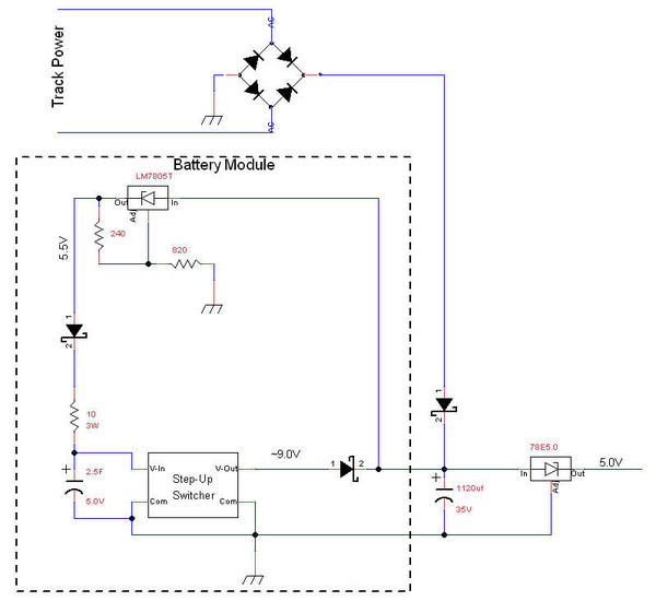
Here's an alternative battery circuit I'm considering. Charging the supercap from the 5V power supply is a problem, if it's running the converter and attempting to power the other circuits, it tends to go into overload and not charge anything. I'm thinking maybe separating the battery function as much as possible makes more sense.


Battery Module

Attachments

Images (1)
  • Battery Module

Battery%20Module

If you install a LM317 (note correction for voltage-regulator mode), then it becomes its own switch that charges supercap only when bridge voltage is present.  So you don't need a transistor switch and just a diode so that supercap does not discharge unnecessarily into the LM317 feedback ladder.  Schottky diodes less than 5 cents in modest qty.


Elaborate on why you need 9V on the stepup.  If the 78E5 says it only needs 7V, this means the stepup will be operating during that annoying "low-voltage" conventional zone between ~7-9V DC.  In steady-state this will mean the 78E5 will be powered thru the stepup and hence the supercap will not get topped off to max potential so to speak.  Obviously with the adjustability on the stepup you'll get to mess with this value but just throwing in my 2 cents FWIW.

Attachments

Images (1)
  • Battery%20Module

Yep, a small oops with the regulator circuit, I kinda' hurried that drawing.


I was unsure if the LM317 would be a problem without a switch, but that's a good thing if I don't need it, the diode is simpler.


The reasoning for the 9V is that I did some bench tests with audio playing and changing modes.  I had to have over 8 volts on the input side for reliable operation, if I was right at 8 volts, occasionally the power supply would drop out and the whole shooting match would reset.  That being the case, I settled on 9 volts for the changeover.  With a full wave rectifier and the normal load, track voltage at around 7.6 VAC I get 8 volts at the input of the regulator.  If I reduce the track voltage to around 7.4 VAC, some audio streams that obviously have a peak surges of sound power trip the supply out and everything stops.  Since I wanted a little margin, I picked 9 volts.  Of course, that's dropped a bit by the diode, so I'm not really getting 9 volts into the regulator.  I can fool with the output voltage once I get one of these assembled and see what works, this is just a starting point.


Here's the "new and improved" battery module.  Once I settle on a design, I'm going to grab an initial supply of the step-up regulators so I have a stock.  I figure the battery modules will only be a fraction of the total sound boards, so I'll just get the parts that may disappear so I have them.  I'm still torn on making a board or skywiring these.  I may have a small board with connections to the step-up and then shrinkwrap the whole thing as a package.


Battery Module

Attachments

Images (1)
  • Battery Module

Well, that's a poorly written 78E5 datasheet (albeit the 1-page version) since it says the input range is down to 7V and 500mA load.  OK so be it.


Note that we're back to the perpetual motion machine if the input the LM317 is AFTER the main board's diode.  It needs to be BEFORE the main board's diode.  Yes, this might mean you need to add a stability cap on LM317 input. This may need some experimentation as with a small cap the LM317 will drop out at 120 Hz at low track voltage.  I don't think this is a problem but that's part of the performance verification.


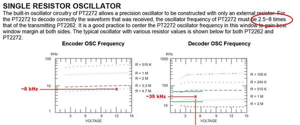
As for the 2272 oscillator.  So as I understand it, as you lower the voltage below 5V it starts to degrade - speculation being it's the bit-rate oscillator drifting.  OK, I see their comment about using the lower value resistor below 5V but frankly this makes no sense given their datasheet curves (albeit typical values vs. guaranteed specs).


pt2262-2272 oscillator

So I looked at my 2262 TX module powered by the 12V batter.  With its 4.7M resistor, that's an osc freq of about 8 kHz.  If the 2272 RX can be 2.5 to 8x, that's a range of 20-64 kHz.  Using their own graph, running at 5V should be about 35 kHz at 5V which is pretty much centered in the range.  And looking at how they extend the voltage range down to 2V on the RX, it seems the 820k resistor remains in the "green" zone even with the low-voltage variability of a 510k or 1M on either side.  I know you're not arguing with me on this point but there's something fishy about why its "falling apart" at 4.7V or just below that with the 820k.  I understand you have bigger fish to fry if you're going down the "full" 5V approach but wanted to comment as it seemed odd that a few hundred mV would affect operation so dramatically.

Attachments

Images (1)
  • pt2262-2272 oscillator

I was wondering what impact the diode would have on having filtered DC for the input to the LM317.  I didn't want to isolate the 1100uf capacitor from the input of the LM317.  However, you're right about the charge loop now.  I can try a small cap for stability on the input of the LM317...


Battery Module

Attachments

Images (1)
  • Battery Module
Last edited by gunrunnerjohn

With the main-board diode isolating the 1100uF, a cap right on the bridge output also perform double-duty as spike protection to protect the LM317 max input voltage.


Separately, I measured (albeit sample of 1) the 2272 pin-15 bit-rate freq on a 4-ch regen rcvr module w/ 820k resistor:


4.0V  ->  26.6 kHz

4.5V  ->  26.6 kHz

5.0V  ->  26.7 kHz

5.5V  ->  26.8 kHz


You saw what you saw, but I'm skeptical it's bit-rate oscillator voltage sensitivity.  Something else must be choking below 5V.  Understood it's a moot point with latest direction but I plan to use these RF modules in the future so I wanted to check it out for myself...


edit: not that anyone is looking but it's pin 15 (not pin 16) of the 2272 that has a measurable square-wave oscillator; I used a 10M scope probe.

Last edited by stan2004

Yep, I think I'm going the full voltage route, don't know what happened there.  I did look at the data sheet and it didn't make much sense that it affected it that much.


The recommended input cap is .1 for the LM317, I think I can afford the three or four cents for one of those.  I do wonder if the diode isolating the main filter I'll need more...  I'm leaning on putting all of this on a small board with the Supercap and just sandwiching the switcher onto it wired into the board.


On a separate note, I ended up with fifteen transmitters (without the receivers) because the one vender tried to pull a fast one and omit the receivers after the fact.  What I bought was the transimitter/receiver set, but then after I ordered, he changed the ad and tried to get away without the receivers.  I ended up getting a full refund, but the transmitters don't work with any of my receivers.  In looking at the transmitters, they have the the 1.2M resistor where all the other ones I have sport the 4.7M resistor for the output oscillator, and of course the receivers match.  I'll be swapping one of these out to see if I have a fist full of extra transmitters when the parts come in.

Last edited by gunrunnerjohn

So as I see it, here's the situation. 


Case 1. Command mode.  1100uF is enough to keep Mr. Recom happy for nominal track-voltage drop-outs.  No option module required.


Case 2. Conventional mode.  At slow speeds with, say, 7 or 8V AC on the track, 1100uF is NOT sufficient to protect Mr. Recom from dropping out and potentially resetting the MP3 module.  So the option-module will provide some fraction of the input power to Mr. Recom....possibly kicking in only on the valleys at 120 Hz.  In this zone the supercap may (due to DC resistance and such) not get fully topped-off since it will be discharging during the valleys. But it should remain sufficiently charged (I'd think 90% or so) to handle a full drop-out from a conventional Direction button press.


This seem acceptable to me.


Sooner than later I'd want to test this with a chopped-sine supply which will effectively have longer/wider valleys than a "pure" sine supply.  I think a DC layout, without the benefits of the AC peaks, may present some issues since the 317 is not LDO; of course the % of O-gauge layouts using DC is quite small but I'd think you'd want to know the limitations and asterisk the behavior nonetheless.


I can't quite articulate my thoughts to make a case but I believe operating on DC is important.  Perhaps I'm thinking large-gauge DC layouts, or battery-operated systems, etc.


BTW I'm assuming the unused (stereo) audio channel is still coming out to a pin?

I have to be honest, I don't think I'm going to try to make low voltage DC work here, I just don't see that as enough of a market to twist in the wind trying to accommodate that case.


I was thinking the same thing about the aux charging for low voltages.  It'll be a balancing act with the correct voltage there coming out of the capacitor's output switcher.


Good point on the chopped waveform, I'll have to try that.


I should be able to simply bring both channels to a raw pin somewhere on the board, I doubt I'll put a connector there.  Likely, they'd be close to the MP3 module to minimize the board real estate the traces use.


I'm "refining" the battery circuit after taking a close look at the supercap specifications and the Schottky diode specifications.  At low currents, the diode only drops .1-.15 volts, and the supercap does NOT like anything over 5V for more than a second.  I'm looking at 5.1 volts out of my regulator to insure I don't cook the cap prematurely.


I figured out my perpetual motion machine.  When I took the transistor out, that's when things went south, I forgot that's why it was in there.


Originally Posted by gunrunnerjohn:
I should be able to simply bring both channels to a raw pin somewhere on the board, I doubt I'll put a connector there.  Likely, they'd be close to the MP3 module to minimize the board real estate the traces use.

Preferably also +5 and GND with those raw outputs.  I agree it doesn't need a connector as this would be for special applications. Conveniently located power is needed to drive the external electronics that takes the raw audio.  Two applications come to mind for starters.


1. 5V powered $1 audio amp for the unused channel.  Not necessarily stereo but I can imagine one system driving speakers in separate boxcars connected only with a 2-wire speaker tether.  So triggering sound #1 encoded only on the Left channel comes out of boxcar A, while triggering sound #2 encoded only on the Right channel comes out of boxcar B.  We'll see what your module price needs to be but this would be one way to add an additional remote controlled audio output for a few dollars.


2. 5V powered tone decoder module to synchronize or choreograph motion or light effect to sound.  I'll have more to say on this as I am messing with the DTMF module I described earlier to decode touchtones on the unused MP3 channel.

Getting back to the big picture, I am convinced this could also be used for track-side or layout sounds - not necessarily rolling stock.  So if the RF module is not used, can a simple module plug in that connector that provides the same 4 "triggers" that come from the RF receiver?  I'd think these would need some simple buffering, perhaps even a 4-channel opto-isolator, so as not to directly drive the uC pins.  I see these 4 wires coming from a) ASC/AIU outputs, b) push-buttons, c) isolated rail or ITAD-like occupancy sensors.


Yes, there are several suppliers of audio modules but I don't think MP3 quality is common in these.  Since this module takes track AC it can obviously be powered by accessory 14-16VAC too...so seems to be a bonus opportunity.  This is especially so if some method is worked out to integrate your other outputs on the IDC.  That is, virtually all layout sound effects have some kind of motion or lighting associated with it.  What's your thinking here?

Several people have already asked about static fixture sounds, so I think you're probably right.  A simple set of four push buttons to 5V will do the trick here, or the equivalent coming from some relay driven device such as the ASC or AIU.  The "trick" for the inputs are that you need to provide multiple button presses at the same time to select modes, so timing becomes an issue.  There is a "ready" output from the remote receiver that I'm thinking of using to tell me there's a new RF value, so you could setup the new value first, and then toggle that bit to trigger the action.  I piped that bit into the uP with the four data bits to give myself that option.


Obviously, you could optically isolate the inputs for best results, that would certainly be the "safe" option.  I suspect that a different plug-in board that provided the non-RF option would be a reasonable plan, that way the main module and MP3 module work exactly the same in any scenario, they just get their data from a different source.


It's certainly possible to envision an intelligent board/box that triggers either the transmitter keys or a direct connection.  That unit could trigger strings of commands as a macro command to do a variety of things.


Obviously, the hardware is there to have synchronized sound and action, it's just a matter of figuring out how to do it in software with the interface we have.


I've tried four different MP3 players, the ones I'm using seemed to have the best sound quality and a pretty healthy 3W amplifier.  They also provide the higher quality micro-SD slot that's easy to use, it's spring latched like most cameras and computer micro-SD slots.  Of course, there's also the fact that this one has the serial data capability with a nice array of capabilities.  I also have about 30 of them in hand, I grabbed them when I saw a good price.  I am getting more of the transmitter/receiver pairs as well, so I'll be ready to put a few of these things out.


One sticking point is getting the software developed and also updates.  One of the reasons I went with the socketed DIP package on the Super-Chuffer was to ease any required software changes, I could just send a new uP and it would be a drop-in.  Updating this unit requires you to have the PIC programmer and also a compatible interface dongle to match the 1.25mm connector used.


Originally Posted by gunrunnerjohn:
The DTMF decoder could clearly be a separate add-on, since the extra audio channel would be available.


This is getting to be a pretty involved system!

So just for fun I whipped together this demo of the DTMF "touchtone" eBay decoder module.  This is meant for the hard-core DIY types.


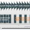
Suppose we use the LEFT channel of the MP3 stereo sound to store the audible sound.  The RIGHT channel then stores sequences of touch-tone sounds that drive the eBay decoder module I showed earlier in the thread.  These touch-tones would be inaudible in the real system but I hooked it up so you can hear/see what's going on.


First here's what the audio editing software might show.  The left audio on top has the repeating crossing bell dinging sound.  The right audio on bottom has alternating touch-tone bursts exactly lined up to the bell sound. 
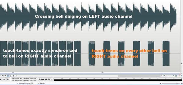
 

dtmf crossing sound and synchronized lights

The DTMF decoder module displays the decoded output on its LEDs.  In a real system the module outputs would drive a relay or whatever to drive the layout crossing gate lamps or LEDs.  For the first few dings the lights alternate on each bell ding.  Later the lights alternate on every other bell.  Yes, in the prototype the alternating lights aren't synchronized to the sound; this is to illustrate the concept of putting the unused audio channel to enhance a sound accessory.  Video below.


I figure the 4 outputs which touch-tone provides can handle most animations.  That is the eBay DTMF module decodes all 16 touch-tones or 0..9, #, *, A,B,C,D (your phone does not use the latter 4 tones).  Using a sound editor (freeware) the idea is you'd simply insert the touch-tone on the unused "control" channel of the stereo MP3 file.  The use of sound-editors and which one is suitable, etc. is a topic in and of itself so I'm purposely skipping over the details to stay on point which GRJ's audio module.


Anyway, if GRJ brings out that unused stereo audio channel, then it can feed the module and each of the 4 DTMF decoded outputs as shown in the 4 red LED lights could drive a relay, motor, solenoid, lamp, whatever.  The DTMF decoder is fast as I think of touch-tone in the 10 events per second range.


So here's another demo, first showing what it looks like in the sound-editor. 


dtmf station and love train

First there's a rapid string of touch-tones on the control channel which makes the decoder dance; there's silence on the audio channel.  Then with the same touch-tone sequence I put some station platform sounds on the audible channel.  Then with the same touch-tone sequence I put some music on the audible channel.  Again, the touch-tone channel was amplified to a speaker to show what's going on but in a real system you would not hear the tones.


We now return you to your regularly scheduled program

Attachments

Images (2)
  • dtmf crossing sound and synchronized lights
  • dtmf station and love train
Videos (2)
dtmf crossing bell
dtmf station and love train
Originally Posted by gunrunnerjohn:
One sticking point is getting the software developed and also updates.  One of the reasons I went with the socketed DIP package on the Super-Chuffer was to ease any required software changes, I could just send a new uP and it would be a drop-in.  Updating this unit requires you to have the PIC programmer and also a compatible interface dongle to match the 1.25mm connector used.


It's a can of worms.  If it's JUST customized sounds, then I think sending an MP3 file is a step forward from the old days of sending a physical sound-chip or re-programmed sound-module.  I figure it is reasonable to ask a user re-program a microSD memory card.


But I'm at a loss for what's "reasonable" when it comes to synchronizing sounds with the other outputs that your module provides (lights, servo, etc.).  On the one hand the hard-core DIYers would probably be using an Arduino with an MP3 module and hence be writing there own program/sketch to effect their complex animation.  So I don't think they are target market. 


I'd like to hear more about this board/box that sequences out macros or streams of commands;  I haven't heard you mention this before (or I missed it).  But whichever way, it sure would be nice if to change/update functionality, a) you don't have to send a physical "thing" around, and b) you don't have to buy/own some programming widget which will get lost, not work with Mac, Windows 10, whatever, and c) you don't have to write "code" to make minor changes yourself.  In my opinion of course...


Well, the sound files are fully customizable by the user, they are on the micro-SD card, and I just pop them into a computer writer to change them.  The card is easily removed, so that's no problem.  Whatever could be triggered from the secondary channel would clearly not require extraordinary effort to load.  Creating the content is another matter.  FWIW, I use Audacity for my audio processing, it's a very capable audio editor, and you have full control of individual tracks if desired.


The door is wide open as far as synchronizing the sounds with the action and lights.  What I'm trying to do initially is to at least have the capability in the hardware to do stuff like this.  I've thought about some basic stuff like having the sense of a car moving and playing one sound, and when it stops, playing another.  Also, the stopped case could also trigger the opening door on a boxcar.  There could be a basic repertoire of canned sequences, but after that I'm still very open to ideas.  I can have a limited configuration capability that you could step through some basic scenarios.


The board/box with the macro commands was all "pie in the sky" speculation on what might be on the other end to drive one or multiple sound/light/control modules, it would obviously have intelligence and some human interface for the operator.  In a nutshell, I'm speculating that the interface could send a sequence of button presses to initiate a more complex scenario much faster than the human operator could manually key them in, thus making the whole operation appear much more seamless.


The reprogramming issue is a sticky wicket, like I said, that's why I went with the removable part.  Right now, I don't have a solution for updating the programming, other than sending it back.

Is it safe to say you don't want to go down the route of the Pricom modules discussed in the other thread on sound effects?


I see it uses a 32-bit Atmel AVR processor IC which reads a user-defined CONFIG file stored on the microSD that instructs how to relate sounds to triggers and outputs.  Obviously this would be a fundamental change in architecture if you have to decode the audio from the microSD...albeit WAV files are easier to decode than MP3.


But if staying with MP3 with the uC only able to see the audio "output" of the MP3 module, then it stands to reason that the programming info must reside in the form of an MP3 file.  So now that we've licked the perpetual motion machine, we can move on to Rube Goldberg devices! 


Remember we're just talking shop here.  Suppose you designate an MP3 file to hold the customization info (how triggers work, how outputs work) similar to what the Pricom CONFIG file holds.  On power-up, your uC "plays" this file (always stored as the 16th ir last "sound") with the audio volume turned off...or maybe it puts this MP3 file on the unused channel and the audio channel plays a voice saying "please wait while I configure myself" or something inane like that.  The uC decodes the file which would be some series of pulses and probably just sound like buzzing if you listened to it.  I figure it might appear to the uC as a 1200 baud serial input which would be fairly simple to decode (simple since I imagine someone else doing this). To be clear, an end-user could not create this file so you'd have to do this.  But the point is you could send this file electronically.

While the idea of individual configurable boards is attractive, I don't think I have any interest in decoding audio to extract digital data.  If I were to go that route, I'd go with a very small DIP package EEPROM and simply read it with the uP, much easier to do, and probably take much less real-estate as well.  Here's a sample, 31 cents in quantity one.  Drops to 24 cents if I buy 100 of them.  To customize the configuration, I just send him another chip for a few bucks shipped.


Microchip Technology 24LC00-I/P


Last edited by gunrunnerjohn

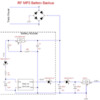
I "tweaked" the battery module and the interface to the board, I think this will work better.  The regulator on the battery module had no filter cap, and that was a problem on my bench tests.  Since there are two caps on the sound board to make up the input filter capacitance, I just moved the isolation diode between them.  I figured that the output from the SuperCAP switcher doesn't need as much filtering that the DC from the bridge.  This allows the battery module regulator to benefit from the first cap and have input filtering.  So far that looks like it works better on the bench.


Edit:  Yes, there's a missing wire from the superCAP to the input of the switching board, but I'll try not to have that in the finished product.


RF MP3 Battery Backup

Attachments

Images (2)
  • RF MP3 Battery Backup
  • RF MP3 Battery Backup
Last edited by gunrunnerjohn

I see your reasoning on just shipping a 25 cent DIP chip for control/sequencing configuration and it is, after all, your circus.  So we can move on.


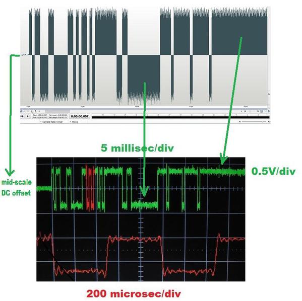
Anyway, I continue to plod along with my plans to the unused MP3 channel for animations and tested the idea of storing a digital data stream in an MP3 file.  So here is the audio editor where I (tediously) hand-edited a digital bit stream starting from a 1 kHz square-wave...so 2000 baud.  The sampling rate is 44.1 kHz.  I was most interested in how the mid-scale DC offset works as well as the ability to generate a DC "high" and "low" digital levels.  Then I plopped the short stream into an MP3 file and played it on my $1 MP3 player module.  The scope shot is shown at the bottom.


digital serial stream test

So far so good.  The red trace on the bottom is a zoom of the red zone in the green trace.  The 2000 baud (500 microsec) pulses seem clean enough for decoding.  The actual output voltage swing is only 1V peak-peak.  But the key is the digital high and low is maintained.  A simple comparator chip or even a properly biased transistor could square this up to a 5V bit-stream that can directly feed, say, the UART/SCI input to a uC chip.  Unlike decoding AC-couple, limited-bandwidth touch-tone audio, MP3 players appear to provide DC-coupled, higher-bandwidth ("fast" edges) raw signals so decoding could be relatively simple.  So, in other words, one could create an ASCII file and store a 1200 baud bit-stream of the file into an MP3 file.  Yes, it seems crazy to go thru the intermediate step of converting from text to MP3 and then back again...but then again if the uC does not have direct access to the microSD card then I think it's an option for the hard-core DIYer that is.


Then I started thinking about the concept of "remote control".  I know nothing about TMCC but I've read your posts about decoding the serial stream from a R2LC or similar module.  So consider this completely pedagogical case.  Suppose someone had a TMCC engine and only wanted a very small subset of controls ... maybe go, stop, blow whistle.  So without needing a command base, you put the engine on the track and use your remote control module to spew out a small set of MP3 serial streams which mimic the few commands to run the engine (or even an ERR accessory).  As I understand it the TMCC serial streams are in the few thousand baud range.  Yes, I can just about see you rolling your eyes even with the Rocky Mountains between us.

Attachments

Images (1)
  • digital serial stream test
Files (1)

It certainly looks like the decoding would be possible from that picture, the data looks as clean as some digital data I've seen.


As you state, TMCC signals are around 3000 baud, I believe that was picked because of the carrier frequency, it does seem to be an odd rate otherwise.


If I wanted to generate TMCC serial commands, why would I go the route of encoding them with MP3 sound and then decoding them?  Since the serial protocol is well documented in the Lionel's The Complete Guide To Command Control, wouldn't it be more to the point to simply generate the required bit stream at the proper bit rate?  I'm not rolling my eyes yet, but I'm trying to understand if I have my $1.50 uP available, why I would generate the codes the hard way.  Of course, in order to impart it on the track, I'd have to generate the 455khz carrier and modulate it with the commands, just as the command base does.  I'm not quite sure what we're accomplishing here.


Using the second stereo channel for other animations, however, does actually look attractive.  One benefit is that you can exactly synchronize the action with the sound, that's a real bonus.  Without having the sound and controls generated together, it's much more difficult to synchronize them.  I think that idea has some possibilities...


Originally Posted by gunrunnerjohn:
If I wanted to generate TMCC serial commands, why would I go the route of encoding them with MP3 sound and then decoding them?  Since the serial protocol is well documented in the Lionel's The Complete Guide To Command Control, wouldn't it be more to the point to simply generate the required bit stream at the proper bit rate?  I'm not rolling my eyes yet, but I'm trying to understand if I have my $1.50 uP available, why I would generate the codes the hard way.  Of course, in order to impart it on the track, I'd have to generate the 455khz carrier and modulate it with the commands, just as the command base does.  I'm not quite sure what we're accomplishing here.

LOL.  I'm not quite sure either!  But for sure I'm not suggesting generating TMCC serial streams via MP3 and then modulating the 455kHz track carrier.  What I'm thinking about all takes place on your module located in the rolling-stock (or engine).  So in one scenario, this would bypass the R2LC demodulation function and directly apply serial commands to whatever takes the R2LC output. Consider the sample application of a boxcar with a door opening, lights turn on, a band starts playing music, solenoid pulses a few times as the singer gyrates, etc.  So previously with an ERR module with multiple outputs, the user would have to send separate 455kHz-track commands to activate specific functions to choreograph the show.  Now, the MP3 control channel would be encoded to send those same serial commands to control the motor, lights, solenoid synchronized to the music and the entire animation sequence would reside on the MP3 file.  You'd still use the power output drivers of the ERR accessory module.  Again, this applies to the case where the uC chip does NOT having access to the microSD data.  Hence it does NOT know what is going on in the music for purposes of synchronization.


As a corollary or whatever, consider a museum display engine on rollers or whatever.  For example, the Pricom site says museum animations are a big application for their audio modules as one would think.  Anyway, suppose you want to run an engine demo with a narration audio track (stored on the MP3 audio channel).  Then on the spare MP3 control track are TMCC serial commands that go to the engine electronics (after wherever the demodulated signal comes out).  This means no command base is needed as you store embed the TMCC commands you need within the MP3 stereo file.  No earth-ground antenna issues or whatever occasionally pops up on the TMCC forum.


But wait, there's more!  So let's say one buys into the idea that it is simple/reliable to directly decode digital data directly from an MP3 stream. I said I'd table the idea of loading the config data if you use a socketed EEROM.  But on paper anyway you could re-flash the program-code of your $1.50 uC.  Of course this is just my backdoor way to put the MP3 version of config data back on the table.  That is, I think of how MTH initially started in PS2 with audio+config information in the reload file.  But now in PS3 the reload file now includes audio+config plus the program code.  And then I think back to how you used to have to change chips to do the same.  Yes, we're talking more and more software but it's so easy since I'm imagining someone else doing the job...


Add Reply

Post

OGR Publishing, Inc., 1310 Eastside Centre Ct, Suite 6, Mountain Home, AR 72653
800-980-OGRR (6477)
www.ogaugerr.com

×
×
×
×
Link copied to your clipboard.
×
×