I think we are at the 2 yard line and it's first down. In other words we're almost there!
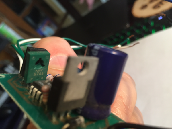
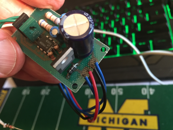
OK. So this might not be photo-graphable but could you peer at the hidden face of the component shown at the red arrow and read the markings? The markings should be something like "B744" white marking on the greenish component shown in photo below but likely something different - a letter followed by 3 numbers. You may have to gently bend one or both components away from each other to read the markings. Since we've come this far, I can draw out a schematic of the circuit for-the-OGR-record. This crossing signal has come up in previous discussions so stands to reason it will come up again!

Also, could you take a photo of your meter or tell me its model number? That is, if you're measuring the VOLTAGE between a green wire and white wire, you should be using a mode-setting on the meter that measures "V" or Volts...rather than "A" which is Amps.
So to be clear, with no meter attached, both controller boards work albeit the one with the added resistor being dimmer?
Ok Stan,
Let's see if we can get it into the End Zone on the first down. ")
The component behind the B744 is: NEC, D794 P, D 2Y
The photo of the attached meter is depicting the setting I was using to make the measurements. I'm certain its not correct, but like I said I'm not very good at electronics as I do not dabble in it often enough to really learn it well.
Also the control board with the extra resistor does indeed dim the crossing buck lights to a very acceptable level while flashing normally.
The control board without the extra resistor does flash normally, but the lights are much brighter.
=============================================================================
Also for those with sharp eyes, that is indeed a Texas Instruments SR-50 calculator on my desk. I bought it new back when they first came out in 1973 during my 2nd year in college. I've used that same calculator everyday since then for school and my job. No need to get anything else.
When the lockdown was about to be implemented, that was the first thing I packed to take home with me in order to work from home. Everything still works and charges like a champ.