Hi,

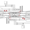
I'm having issues wiring these DS's. I have 4 Double Slips with 2 of them in different spots of the 3 loop layout. I want to wire these for the non-derailing feature to work from all sides without using relays. Wondering if this is at all possible? I can get slip number 1 to work correctly but the 2nd slip will work from 2 sides but the other ones will not. Any tips on how to wire these correctly?? I followed the directions that came with the switches but still having issues. Looked on you tube and ross web site but not much help. This is my 3 rd layout so I'm somewhat fimilar with this stuff but my first time with the DS's.

Thanks in advance!

DanRoss DS Sw 1 of 2Ross DS 2 of 2

Attachments

Images (2)
  • Ross DS Sw 1 of 2
  • Ross DS 2 of 2
Original Post

Replies sorted oldest to newest

Still need some help with this? I have on of these DS on my layout, but have not wired for derailing yet. 

As normal, you need insulated rail sections, so the the DS, you need 4 isolated rail sections, one for each "arm" of the DS. I have added in red the area where you need the 4 isolated rail sections in the DS diagram from Ross. To each isolated rail section, you need to solder a wire that will reach either of the two DZ2500 switch machines of the DS.

dblslipadvanced derail

I don't have power to my DS at the moment, so you will need to do a bit of experimenting on your own. You only use the Green and Yellow wires of the DZ2500 switch machines. The experimenting is that I can't tell you which wire from what switch machine you need to connect to a particular isolated rail section. First, pick a leg you want the derail to work on. Next, determine which DZ2500 needs to be energized to prevent the derailment. Now you at least know which DZ2500 to hook up to the isolated rail in the leg you have started with. Try the green wire, put the switch in the position to derail, move a car by hand into the isolated rail, and see if the switch changes to prevent a derail. If not, disconnect the green, and connect the yellow, then repeat the move car by hand to test.

You can email me at my email address in my profile if you need some more help.


Attachments

Images (1)
  • dblslipadvanced derail

Took a look at the wiring schemes of the breakout board to DZ-2500. Also looked at DZ-2500 to DZ-1008. Looks like the DZ-1008 would be spliced in between the Breakout board and the DZ-2500 connecting to the Red Black Green and Yellow wires as per Z-stuff wiring diagram for DZ-1008 to DZ-2500. Not sure why you want to do this unless to wire to block signals maybe, or power routing? The breakout board has connections for non-derailing feature. This is the first I have looked in to this but unless there is a power restriction on the breakout board I would think one board could be wired to control two opposing switches. Placement of the derailing wires for the out position may be a little tricky but since both opposing switches will be thrown in the out position at the same time. It would possibly not be needed at all.

You will have to download PDF's from Lionel and Z-stuff for the wiring diagrams. I haven't figured out how to link them here.

I never used the DZ-2500's to TMCC or Legacy. Z-stuff had the 2001A data wire drive. At one time there was a lot of discussion of having the switches chained together with the data wire driver and if one switch in the chain failed I thought all of them had to be programmed again. This was enough to stick to push button control at the control panel. It was quit intensive to wire but when a DZ-2500 or DZ-1000 fail all we have to do was wire in a new one. No programming . Things have evolved a lot further since then.

@Forest posted:

I never used the DZ-2500's to TMCC or Legacy. Z-stuff had the 2001A data wire drive. At one time there was a lot of discussion of having the switches chained together with the data wire driver and if one switch in the chain failed I thought all of them had to be programmed again. This was enough to stick to push button control at the control panel. It was quit intensive to wire but when a DZ-2500 or DZ-1000 fail all we have to do was wire in a new one. No programming . Things have evolved a lot further since then.

I don't think you have to reprogram everything for a failure, that must be some of the older stuff.

PLEASE, look at the DS wiring diagram carefully. The switch motor which is thrown for non-derailing, on either side,  will not be the same switch that will cuts power  to the respective track sections 1,2, and 3,4 ( if you are using relays). Depending on the original route, the other switch may have to be thrown also. I use CAB2 routes to program my DS; left to right 1(A-A), 2(B-B), 3(A-B), 4(B-A). I have two switches attached to the B legs which may also throw for routes 2,3, and 4.

Last edited by WinstonB

I see that's the way it's drawn up, but I see major issues in that arrangement.  Convince me I'm wrong...

Refer to the diagram below, you'll probably have to click on it to expand it.

Let's say I'm entering on the left at A and exiting on the right at D, and the #1 rail on the left has been switched to center track power.  All is well and I transition the switch.

Now I enter on the left at A and switch the right to exit at C, the #2 rail on the left is now switched to center track power.  All is NOT well, and I have a direct short across track power and promptly trip the breaker!

Double-Slip Switch Power Switching

Updated picture to show switch machine link to movable rails.

Sorry, but I don't see this working, if I'm wrong, what am I missing?

Attachments

Images (1)
  • Double-Slip Switch Power Switching
Last edited by gunrunnerjohn

John

I think about it as if it’s 2 separate switches, split down the middle.  Lets say switch machine 1 changes route A/B and switch machine 2 changes route C/D.  With your scenario, you are only changing switch machine 2 and therefore only changing power to rails 3 and 4. Since you are going though route A both times, you are not touching switch machine 1, therefore not changing power on rails 1 and 2.

Last edited by Tanner111
@Tanner111 posted:

John

I think about it as if it’s 2 separate switches, split down the middle.  Lets say switch machine 1 changes from route A/B and switch machine 2 changes from route C/D.  With your scenario, you are only changing switch machine 2 and therefore only changing power to rails 3 and 4. Since you are going though route A both times, you are not touching switch machine 1, therefore not changing power on rails 1 and 2.

Jim, that's not the way that it's written up by Ross or described by WinstonB below!  I've quoted his message and attached the Ross DSS wiring diagram PDF as well.  You can clearly see they have the switch machine controlling the right half switching the powered rails on the left half, and vice-versa.  IMO, this is clearly wrong, and I can't see how it would work.

I'm with you, IMO it should be treated exactly as two switches, that's the way I'm using it, and I'm going to wire it that way as well.  I can't see any way that it could work with the wiring proposed in the Ross DSS document or by WinstonB.  I will be questioning Steve at Ross on Monday about that wiring diagram as well.

I updated my original picture to illustrate which switch machine is switching which side with the dotted arrows.

@WinstonB posted:

PLEASE, look at the DS wiring diagram carefully. The switch motor which is thrown for non-derailing, on either side,  will not be the same switch that will cuts power  to the respective track sections 1,2, and 3,4 ( if you are using relays). Depending on the original route, the other switch may have to be thrown also. I use CAB2 routes to program my DS; left to right 1(A-A), 2(B-B), 3(A-B), 4(B-A). I have two switches attached to the B legs which may also throw for routes 2,3, and 4.

Double Slip Switch Wiring.pdf

Attachments

Last edited by gunrunnerjohn

Jim, that's not the way that it's written up by Ross or described by WinstonB below!  I've quoted his message and attached the Ross DSS wiring diagram PDF as well.  You can clearly see they have the switch machine controlling the right half switching the powered rails on the left half, and vice-versa.  IMO, this is clearly wrong, and I can't see how it would work.

I'm with you, IMO it should be treated exactly as two switches, that's the way I'm using it, and I'm going to wire it that way as well.  I can't see any way that it could work with the wiring proposed in the Ross DSS document or by WinstonB.  I will be questioning Steve at Ross on Monday about that wiring diagram as well.

I updated my original picture to illustrate which switch machine is switching which side with the dotted arrows.

Double Slip Switch Wiring.pdf

John

Now I see what you’re saying.  I am curious what Steve says.

I believe Ross' DS diagram is correct.  The DS is my next switch to install, and a few months ago I set it up on my workbench to see how it worked.  Sorry it took me a while to put my chicken scratch drawings into PowerPoint, but here it is.

The left side of the chart shows which lead rails need to be energized for the trains to make it through the switch.

The right side of the chart shows which lead rails are energized for DZ-2500 switch position.  This assumes all 6 wires from the DZ-2500 are connected to the breakout board and the green and yellow wires of the DZ-1008 are connected to any of the breakout board's green and yellow inputs.

For DZ-2500 'X', green LED has switch machine energizing the white wire (#1), red for gray (#2).  For 'Y', green LED has switch machine energizing the white wire (#4), red for gray (#3). 

DS_lead_rail_wiring

At least I hope it works this way or I'll have a couple of burned out DZ-2500s.

Attachments

Images (1)
  • DS_lead_rail_wiring

In my mind the DSS is just two switches back to back, so if I treat them that way, it's not problem to see how the rail switching works, you do it just like you would on any other switch that needed power to those rails.

In your graphic, you have the rails to be energized correct, but I question how you get there, because using the Ross diagram, I don't believe you can.  I see no way that if I'm coming in the A track on the left side and controlling the power to the dead track sections from the right side can possibly work.  For one exit path, I'll have a direct short every time!  However, if I control the relay from the same side, it's no problem to make it work.

Go back to my drawing and explain how you make it work with the Ross wiring.

It makes no sense to me and has to be a mistake.  There's no way that could work!

I wired my DS just as the diagram shows from Ross with relays. However, I did not wire for non- derailing.  I set the desired CAB2 routes before a train enters the DS. CAPPilot’s operation as described is the setup I have. You observation is correct that’s why all my routes are set by me manually. My post was for those attempting to wire for non-derailing operations, using the Ross setup,  to point out the issue with the various powered sections labeled 1,2,3 and 4.

Last edited by WinstonB

John,  All I can say is it worked for me back them.  I hope to have the DS in by next weekend so we will see.

I also played with the non-derailing.  I think it will work but you will not have a choice as to which way it goes out of the switch.  You have 4 ways into the switch, but each of those 4 ways has two ways out depending on how the other switch machine is set.  If it goes onto a track with a train on it you might get more damage than if you had just let it derail.  I'm going to solder the derail wires onto the switch before installation, but not sure I will use them.

Last edited by CAPPilot

I have played with the switches and the paths through the switches.  I'm not sure what issues you foresee using the non-derailing, but I'm not anticipating any issues there, and my testing by sky-wiring the switch and running my battery powered locomotive through the two DS switches worked just fine.  Remember, non-derailing only pertains to the entry side, the exit side is set to whatever route you desire (or maybe to one you don't desire!).  However, there is only one potential trigger for the non-derailing if you wire it right, when you exit the DSS, the non-derailing logic should be such that the switch machine is already in the position that is being called for by the non-derailing rail connection, hence no switch movement.

As for the DZ-1008 relay wiring, I'm still not seeing how wiring the relays for the DSS like the Ross diagram can possibly work.  I'm sure not going to wire them that way until someone convinces me with solid logic that it will.  In two or three sentences I explained why it can't possibly work, and all the postings since have not refuted the facts as I presented them.  I'm waiting to be proven wrong, but I just don't see it yet.  That being said, it's hard to believe those diagrams from Ross have been around as long as they have and nobody has had a problem, that I don't understand!

The phone lines are open and operators are standing by!

Last edited by gunrunnerjohn

Add Reply

Post

OGR Publishing, Inc., 1310 Eastside Centre Ct, Suite 6, Mountain Home, AR 72653
800-980-OGRR (6477)
www.ogaugerr.com

×
×
×
×
Link copied to your clipboard.
×
×