Yesterday evening, I watched an excellent video - featuring real steam locomotives; it was mostly old, but good, footage.


This one particular segment featured, the biggest steam locomotives, used in North America; including, Norfolk and Western and Union Pacific equipment.


One of the things that caught my attention, was seeing the side rods etc. moving at extremely high speeds; it had an EXTREME -  SOMETHINGS GOING TO BREAK look... at those speeds.


So many, fairly large, moving parts; it looked like it would be physically impossible, for those components to move any faster; and, if they were able to... something would give.


This must have required significant ongoing maintenance, to keep these massive machines... working and safe.


I think that type of steam locomotive technology, must have reached it's limit...


BTW, it's fortunate that some people went to the trouble of capturing these unique machines, in action, for future generations to enjoy/see.


Rick

Original Post

Replies sorted oldest to newest

hello Rick B...........


Do you meant siderod "flexing" as where it is flexing and reaching to a point of breaking ?  I would imaged this can happen to such as U.P.'s #9000 4-12-2 thus having too many drivers connected to one siderod.  Did such as thing happen ?


the woman who loves the S.F.5011,623

Tiffany

Originally Posted by Rick B.:

Hi Tiffany,


Some of the footage showed them running wide open, with the rods etc. moving almost impossibly fast; I can't see man-made equipment being able to withstand that type of stress, for very long, without something breaking/failing. It appeared extreme... at it's upper limit!


Rick

That's why the locomotive design engineers had slide rules, log tables and mechanical knowledge, to prevent things from flying apart.


Rusty

hello guys and gals.........


I can see that for the siderods to spin really super fast would be toy trains as they are good at that !!!!  A good example would the lionel #681 turbine, try running it at 18 volts and watch the siderod move !!!!!!!!!. I think that's what Rick B is saying about the real engines doing that !!!!


the woman who loves the S.F.5011,623

Tiffany

Originally Posted by Rick B.:

Tiffany,


I'm thinking there's an upper limit, re: size, shape, material used... and how fast is can move. Exceed that and you're in trouble.


I wouldn't want to be anywhere near, a high speed failure...


Rick

Here's something for you to worry about...  Almost every nut on a steam locomotive is held in place by a lowly cotter pin.

Rusty

Originally Posted by Tiffany:

hello Rick B...........


Do you meant siderod "flexing" as where it is flexing and reaching to a point of breaking ?  I would imaged this can happen to such as U.P.'s #9000 4-12-2 thus having too many drivers connected to one siderod.  Did such as thing happen ?


the woman who loves the S.F.5011,623

Tiffany


Hi Tiffany,


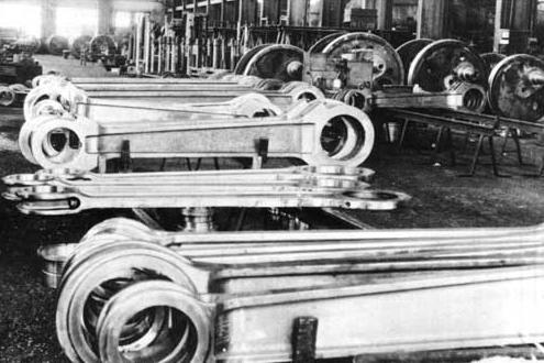
The siderods on the prototype locos (and better models) are not one continuous piece. Separate rods connect each adjacent pair of drivers. This is necessary so that each sprung driver can move vertically on its own. One long rod would not allow for independent motion. 


Here are some typical side rod sections:


rods


Materials engineers had become pretty good at calculating stresses and the limits for various materials at speed by the time that the big steam locos appeared. In the early days, there was indeed some trial and error involved in determining safe limits.


Jim

Attachments

Images (1)
  • rods
Originally Posted by Rusty Traque:
Originally Posted by Rick B.:


This must have required significant ongoing maintenance, to keep these massive machines... working and safe.


Yes, it did.


That's why the railroads employed boilermakers, pipefitters, machinists, mechanics and helpers.


Rusty

I have a DVD set at home that my wife gave me for a Christmas present a couple years ago, which includes all vintage films that were made either by railroads or someone else for promotional use or employee use.

One DVD contains all British films, and one is incredbly interesting, in that it shows when they take a steam locomotive off line and do the regular maintenance. 


Essentially, the locomotive was down to the bare essentials and thoroughly gone over before going back into service.


Something being run under that much pressure with that many moving parts simply needs it!

Roller bearings and automatic lubricators made a huge increase in the reliability of steam locomotives, but they could still fail when routine maintenance was neglected. One of the Milwaukee Road's streamlined Hiawatha 4-6-4 Baltics was destroyed when a lubricator failed and a rod bearing seized. When the railroad investigated this horrendously expensive failure, it turned out that crews had been complaining about the offending lubricator for a while, but the shop crew had just fiddled around with it instead of rebuilding it as they should have done. Perhaps it was just sloppiness, or maybe pressure to keep the big streamliner in service. The locomotive was never put back in service; it was sidetracked and cannibalized for parts until all the units were scrapped. 

You do realize that the same thing happens inside your automobile engine?  Connecting rods are not just some simple piece of cast iron.


There are times when I am convinced that mechanical engineering was better in the first half of the 20th century than it is now.  Most of my good machinery was designed in the 1930s, by Ford, Continental, Lycoming, and South Bend.  My 2003 Ford Ranger was designed by incompetents.


Opinion.

Originally Posted by Southwest Hiawatha:

Roller bearings and automatic lubricators made a huge increase in the reliability of steam locomotives, but they could still fail when routine maintenance was neglected. One of the Milwaukee Road's streamlined Hiawatha 4-6-4 Baltics was destroyed when a lubricator failed and a rod bearing seized. When the railroad investigated this horrendously expensive failure, it turned out that crews had been complaining about the offending lubricator for a while, but the shop crew had just fiddled around with it instead of rebuilding it as they should have done. Perhaps it was just sloppiness, or maybe pressure to keep the big streamliner in service. The locomotive was never put back in service; it was sidetracked and cannibalized for parts until all the units were scrapped. 

I forget whether it was Classic Trains or Trains magazine that ran an article covering that incident.


The article had a Ted Rose painting of the locomotive as the destruction was happening at speed. 


Rose effectively captured the rods as they were flying apart chewing up the running board and sheet metal.  Even for a painting, it was a frightening image.


Rusty

Certainly by the 1930s, the engineering of steam locomotives was mature - the forces involved were well understood and the calculations needed to engineer equipment well  fairly precise.  Side rods and all other equipment was designed with enough strength, bearing surface, etc., to handle the stress expected.  The motion may look fast, but most locos ran at perhaps up to 200 RPM.  Same with large reciprocating steam plants.  I saw a film once of the engines on the USS Texas, one of the last US capital ships with reciprocating steam, prior to turbines.  That size pistons and rods, moving at perhaps 80 RPM, are just frightening to watch!  Wow.  Designing modern car and aircraft engines for 6000 to 9000 RPM is just as much a challenge and puts parts under just as much stress.  And as always, if overreved, poorly maintained, or overstressed - things come apart.


That's why the locomotive design was outlawed; when a side rod went it took out the cab and whoever was sitting on that side ... wasn't it a Union grievance that finally pressed the issue?
 
When installing the rods the nut is driven on with a slug-wrench and a sledgehammer until the sound it makes when struck with the hammer is "just right".  Then the very large cotter-pin is installed to keep the nut from turning.
 
Doing the rounds tapping the nut with a hammer confirms it's still tight.  A loose one will have dull sound instead of a "ping".
Others may do it differently.
 
What's the practice on the NKP 765?  Rich might know the answer.
 
A rod coming loose at speed would indeed be a very bad day. 
 
Originally Posted by WindupGuy:
Originally Posted by Tiffany:

That explains why the cabs are in the back of the steam engines rather in the middle for this reason.

Exactly right, I've seen a couple of pictures of "Mother Hubbard" locomotives that had side rods or connecting rods break... the result isn't pretty.


Last edited by Kerrigan

A great discussion on a high-tech subject!  Railroad engineering designed these rods  thicker than they needed to be - but how much thicker was always debated - 100%? - 80%? - 60%? LIMA sent their design of the Allegheny Main Rods to the C&O - and the C&O responded by saying "Make the cross-section larger." LIMA responded saying they were confident that their design was sufficient. C&O repeated their instruction to "make it thicker". So more weight was added to an already too-heavy locomotive at the insistance of the Railroad. And then the railroad later sued the builder for the locomotive being too heavy! Whoa!

Let's remember the NYC Hudson slip tests where they slipped a Hudson at 142, then 147 MPH and higher - to confirm their counter-balance calculations. Those rods were changing direction 10 times a second! Well over 200 RPM! 300? Maybe more! These were tested in the middle of a regular run - with NO ill effect. 

When I was a kid I was in the liberry.I found a book about train wrecks.In it was pictures of sid rods breaking.And sometimes the resuilt was some one geting killed.Now to me having the rim of the wheel come off.While moving at 75mph this happen to a b&o steam locomotive.But the crew managed to stop the train before a derailment could happen.And bob2 is right about cars.

Originally Posted by Gary P.Bensman:

A great discussion on a high-tech subject!  Railroad engineering designed these rods  thicker than they needed to be - but how much thicker was always debated - 100%? - 80%? - 60%? LIMA sent their design of the Allegheny Main Rods to the C&O - and the C&O responded by saying "Make the cross-section larger." LIMA responded saying they were confident that their design was sufficient. C&O repeated their instruction to "make it thicker". So more weight was added to an already too-heavy locomotive at the insistance of the Railroad. And then the railroad later sued the builder for the locomotive being too heavy! Whoa!

Let's remember the NYC Hudson slip tests where they slipped a Hudson at 142, then 147 MPH and higher - to confirm their counter-balance calculations. Those rods were changing direction 10 times a second! Well over 200 RPM! 300? Maybe more! These were tested in the middle of a regular run - with NO ill effect. 

For me, thats part of the interest/facination with steam locomotives. Theres certainly something to be said for the engineering skills of 70 years ago where they could keep such large masses of metal turning at great speed in balance without coming apart.


These days, even though its done on a computer your lucky to get a new set of tires on your car balanced correctly.

Originally Posted by mlavender480:
Something can "give" on any piece of reciprocating/rotating machinery... Ever see a Top Fuel dragster launch a piston?

It could and did happen on steam locomotives... But not often enough to be "routine".

On Star Trek, when Scotty would say "Captain, she's gonna blow," she never did, but in the real world it doesn't work like that.   


I have a piston and very bent rod from a '98 Camaro LS1 I keep in my office bookcase at work.  I had installed a dry Nitrous on it when new to boost power about 50-75 HP, but after I gave it to my youngest boy, he just kept jetting up the NOx inbjection to get better quarter mile times.  I warned him, but it was his car.  With somewhere around 233 additional HP from NOx, he was headed for somewhere in the 11s when the engine just let go about a hundred yards from the end.  

I had a rod break at 300 feet over an Oklahoma soybean field.  The end attached to the crankshaft tore the engine case apart and rendered two cylinders sem-useless.  Covered the windshield with oil.


The engine was still running on three cylinders.  I think it would have put out enough power to get me to a bigger field, but I shut it down and landed in the beans.

My sister enjoyed a similar moment in an Aeronca Champion during an early solo when she was taking flying lessons.  She landed pretty well in a field, but ran through a ditch and took the wheels off, bent the prop, etc.  My father was NOT happy, but it's not like she had a choice.   I personally never experienced a total engine failure in several thousand hours of flying, closest I came was a magneto failure.


I understand the issue with the Camelback locomotive was breaking rods coming through the cab and having an adverse effect on the crew.


First time I've heard of an engine that kept running after throwing a rod. It says something for the basic design of a radial engine - I doubt any other engine type would have kept going. I assume they just dropped in a new mill and saved the three good jugs and whatever else was left for parts. Was the crank still usable?

Originally Posted by bob2:

I had a rod break at 300 feet over an Oklahoma soybean field.  The end attached to the crankshaft tore the engine case apart and rendered two cylinders sem-useless.  Covered the windshield with oil.


The engine was still running on three cylinders.  I think it would have put out enough power to get me to a bigger field, but I shut it down and landed in the beans.


Found the picture of the Camelback with the cab wiped out by a broken rod:


Incidentally, my copy of the "Locomotive Catechism" by Grimshaw has an extensive section on how to deal with various breakdowns on the road.  He devotes the better part of 6 pages just to "Accidents to Main and Side Rods."  It is interesting - assuming you have a fascination with steam locomotives!  My copy is from 1923, but it was originally written in 1893... there was a lot of progress in the technology of steam in that timeframe.  Well worth picking up a copy if you find one.


I'm amazed that there weren't more rod failures in the early days of steam, considering the accepted practice of using a strap bolted to the rod that contained the split brasses and wedges.  That is a lot of parts - all held together with bolts - that had to stand up to the tensile forces from the thrust of the piston, as well as resist the centrifugal forces trying to separate the rod from the straps.  This is an example of the standard practice of the era... it is on the "Eddy Clock" 4-4-0 at the St. Louis Museum of Transportation, one of my favorite locomotives there:


Side Rod detail on Eddy Clock


I love those early steamers!

Post

OGR Publishing, Inc., 1310 Eastside Centre Ct, Suite 6, Mountain Home, AR 72653
800-980-OGRR (6477)
www.ogaugerr.com

×
×
×
×
Link copied to your clipboard.
×
×