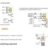
Slow tortoise here . . . .    Many thanks to all of you very patient folks walking me through the nether world of electronics. I am beginning to understand this and I hope that is a good thing. 

1) Now I understand that to use the DCS AIU to throw my Tortoise switch machines I will need a latched relay    (I assume one per switch) and that idea is not going to fly. I will throw the Tortoise machines with SPDT switches. So . . . . . 

Are there SPDT switches that light with red and green depending on the curved route or straight route when I throw the switch? If so, can someone please point me to nice SPDT switches that will look good on the fascia of my layout or on some kind of switch control panel? Can you please tell me where to buy these things? When I look online there are confusing "ratings" for these things and I would like to save time and aggravation. 

2) The New Munoz Lines Will be an island type layout with an "inner" steam yard requiring a duck under for access  (another long story for another time !) and I will want to place the SPDT switches in the yard area not on the outside of the layout so, I guess, I will end up with more than one panel of SPDT switches depending on where on the layout the turnouts are located. So . . . . .

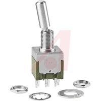
Can someone suggest how I might design these individual switch control panels in/on which I will mount these SPDT switches? For example, here is a switch that looks like it has red/green and a little box panel that seems like it would work OK. I do not need to have the track diagram on the panel as that seems a bit complex. I dunno, is there a better way to do this? 

BoxRG switch

3) For my sidings, I would like switches that turn the power on off. I need switches that simply          light = on and no light = off. Suggestions? Perhaps I can buy all of these switches in one place .  . ?

The slow tortoise is actually learning with all of your help and I do appreciate your patience. It is somewhat embarrassing to keep asking these question that seem pretty basic. Many thanks !!

Scrapiron Tortoise

PS: Mike, you e-mail did not work. Can you hit me with an e-mail?


Attachments

Images (3)
  • Box
  • RG switch
  • Scrapiron Tortoise
Original Post

Replies sorted oldest to newest

Tortoise installation instructions.   Click on the link. 

(1.)  A DC power supply, though there are other options, probably the best and least complicated, IMO.

(2.) Use the number (1) wiring diagram that uses two position double pole/double throw switches.


DC with Two position,  double pole double throw (DPDT) switches.  On/On.

A switch that would work.   Click on the link.


This system uses the most basic power source, a simple DC supply of not more that 12 volts.  Lesser voltages will make the TORTOISE run slower (and quieter).  The power supply need not be filtered. Each TORTOISE will draw 15 to 16 ma (milliamps) at stall, so 30 switch machines can be powered by a single 9 to 12 volt 500 ma, wall plug adapter (available from Radio Shack).  Any type of DPDT switch (toggle, slide, etc.) can be used to switch the polarity.  This system will have two wires running form the control panel to each TORTOISE. See Diagram 1.  (Instructions)

2.  There are contacts in the Tortoise switches, two sets NO/C/NC  Normally Open/Common/Normally Closed.  One of the sets could be used for control panel or track side indication lights.

Give me a call. 

Mike CT.   


Last edited by Mike CT

Our entire panel is full of toggles from HERE. SPDT for track power for all sidings and engine tracks, DPDT for Tortoise switch machines

We use a Bi-Color LED for switch indication. Yellow/Green --Green = normal route, Yellow = alternate route

You could do the same thing with a Red/Green LED... This way, one color is always lit and you're only wiring 1 LED to the toggle. It's just my opinion but when you use 2 LEDS (red and green), only 1 of them is lit at any given time. By using 1 Bi-Color LED, the LED is ALWAYS lit. Most people use a red and a green.

In the rail yards where I work, all the controlled switches have yellow/green indicators. After all, red means STOP. If we see a RED signal, we have to stop. So that's why I used Green for NORMAL and Yellow for ALTERNATE.   

We did NOT use LEDs for track power indication just because it's easy to see UP is on and DOWN is OFF. Eliminated a lot of extra wiring to show something on the panel that we could already see. Again, just the way we wired it.

Last edited by Laidoffsick

Eliot

I also have an island type layout with access to center. You do realize more than likely you will operate from both inside and outside. you will need toggles for every switch inside and outside. that is why I use the remote. But better than that are the new WIFI systems. Operate the switches only with a tablet ? I like the layout of the lionel one better, but the MTH I know will operate the tortice. 

Yes, this is old school, and we have to be at the panel to throw switches. BUT.... there is no way we could memorize all the switches and track power toggles to run the whole layout by remote. Not to mention all the extra wiring for AUI's or SC-2s.

All of our Tortoise machines are wired exactly as Mike described above with two DC walwarts.

Jan 2016

Attachments

Images (1)
  • Jan 2016
Last edited by Laidoffsick
Scrapiron Scher posted:

...

1) Now I understand that to use the DCS AIU to throw my Tortoise switch machines I will need a latched relay    (I assume one per switch) and that idea is not going to fly. I will throw the Tortoise machines with SPDT switches. So . . . . . 

Can you elaborate on why a latched relay (one per switch) derails the remote-control (AIU) option and puts you back to a SPDT lever switches?  Cost?  Suitable latching relays can be had for just a few dollars each.  Wiring hassles?  As pointed out in your other thread, you can use the Accessory Output relays (10 per AIU) to provide the "latching" function.


Stan, Not really knowing what I'm talking about is central to my agita. I looked up the type of latched relay I thought I needed and it was $35. I had no idea it was a couple of bucks. But . . . Being able to wire a basic setup is challenging enough for me. I have enough difficulty getting under the layout for a short time. The latched relay stuff just was overload for me. I would much rather use the DCS Wifi set up but, honestly, the whole latched relay thing seems beyond my wiring ability. I want to be on top running trains not under the layout being an electrician.

I will try to re-think this but the more I think the deeper I sink into the quicksand. I didn't realize with the Tortoise machines when I bought them it was a "constant" DC or whatever it is called. I never really had issues with the Atlas O switch machines but I had heard so many good things about the Tortoise, I thought I would give it a try. Now, before I know it, I am into DC and latching relays and it fries my brain. Truth.

Eliot

You asked about control panels.

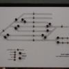
TOP PHOTO. 30 years ago 3mm MDF painted white, then narrow masking tape for the tracks, then paint all over with your colour (mine was orange!) remove tape drill holes mount switches.

BOTTOM PHOTO.Today 2016 still 3mm MDF, paste a Cad drawing of track plan, drill holes mount switches. I won't go into latch relays and tortoise. Roo.MVC-010S 30th Novembe r2012 018

Attachments

Images (2)
  • MVC-010S
  • 30th Novembe r2012 018
Scrapiron Scher posted:

Stan, Not really knowing what I'm talking about is central to my agita. I looked up the type of latched relay I thought I needed and it was $35. I had no idea it was a couple of bucks. But . . . Being able to wire a basic setup is challenging enough for me. I have enough difficulty getting under the layout for a short time. The latched relay stuff just was overload for me.I would much rather use the DCS Wifi set up but, honestly, the whole latched relay thing seems beyond my wiring ability. I want to be on top running trains not under the layout being an electrician.

Understood.  All this talk about DC, DPDT, SPDT, latched relays, etc. can be tedious.   That said, it's your railroad and if you want to use DCS (with an AIU) to control the Tortoises, then let's get all the cards on the table!  If the cost, wiring hassles, etc. rule it out for whatever reasons then so be it...the last thing we want is buyer's remorse, "I could've had a V8".

Some comments in no particular order.

Yes, suitable latching relays can be had for about $2.  But these are just the bare relays and indeed require soldering fine wires.  I figure you can pay more (perhaps a lot more) and buy DPDT (double-pole, double-throw) latching relays already mounted on a board with screw-terminals but just trying to show a starting point.  So this would use the method MTH shows for controlling a Tortoise using the AIU's Switch outputs:  http://www.protosound2.com/pdf/AIU_Tsw.pdf

dpdt latching relay 12v example

As you've apparently discovered, you can use a "less complicated" SPDT (single-pole, double-throw) wiring scheme if you have a source of DC+ and DC- voltage.  In the DPDT methods, the 2nd pole of the electrical switch (or relay) is used to reverse the polarity of the voltage for the reverse direction.  If you already have separate sources of + and - voltages, you can eliminate one pole.  Suitable 12V DC power sources such as wall-warts are maybe $2-3 each...or you can derive your own from AC Accessory Voltage from your transformer using a few 25 cent diodes.  Both these methods are illustrated in the Tortoise instructions/application notes.

But back to the DCS matter at hand.  So as was pointed out in your previous thread, if you use the AIU Accessory Outputs (vs. the Switch Outputs) you can use the SPDT wiring scheme since that's what's in the AIU Accessory Output.

aiu switch accessory contrast

This can be a bit of a nuisance to actually operate since with the AIU Accessory control you don't get the "Straight" and "Turnout" icons but have to use generic "ON" and "OFF" menu selections and mentally convert to "Straight" and "Turnout".   To be clear, the above is not a complete wiring diagram as it doesn't show the DC power supply hookups.  I also show the screw-terminal adapter boards which are available for about $5 which plug on to the Tortoise module and allow you to skip soldering wires onto the switch machine itself.

So in summary, there are (at least) two approaches to the DCS option.   If you go with the more complicated DPDT latched relay approach, it can be made to offer simultaneous control using a layout control panel using push-button or lever switches.   In other words you could control the Tortoises using the DCS/AIU remote control or by manually flipping/pushing buttons on a control panel like those several of the guys have posted.

Finally, generally mentioned in threads about using an AIU to control switches (whether traditional or Tortoise type) is the ability to set, in one fell swoop, all switches under AIU control to a known position using the Route or Scene function.

I'll make a separate posting with comments about switches but wanted to separate the DCS option so as not to muddle things more than I'm sure I've done!  

Attachments

Images (2)
  • dpdt latching relay 12v example
  • aiu switch accessory contrast
Last edited by stan2004

If going the layout/control panel approach using switches, the key diagram is from the Tortoise instructions:

tortoise wiring options

Mike CT shows the following DPDT switch which uses option 1.  Laidoffsick shows a vendor with a wide variety of switches but here's a DPDT switch suitable for the Tortoise option 1.

DPDT switches as recommended

To your point, it can indeed be overwhelming trying to interpret electrical specifications.  In the case of controlling Tortoises, the electrical currents involved are so small (fraction of an Amp) that pretty much any DPDT switch will work.  It really comes down to finding one that has a look-and-feel you like.   In my opinion you shouldn't have to pay over $10 for a switch - I'd say $2 is a good target price.  But note the screw terminals (no soldering required!) of the first switch.

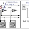
If you go with option 2 or 3, you only need SPDT switches.  They have only 3 connections (rather than 6 as on a DPDT) but will essentially look-and-feel the same as DPDT switches.  Not half the cost but maybe, say, 25% less than a DPDT.  As discussed in previous post you need to supply a DC+ and DC- power source.  In practical terms if you only have a couple Tortoises, it may make sense to just use option 1 and go with DPDT switches and a single 12V DC supply.

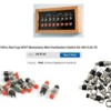
You show a control box in one of your posts showing Red and Black pushbuttons.  Presumably you momentarily press one color to activate "Straight" and the other color to activate "Turnout".  This is yet another wiring option (not shown in Option 1..3) more like the traditional AC solenoid switches with momentary spring-loaded lever controls.  To drive a Tortoise, you would need to add a DPDT latching relay.  But as switches go, these pushbuttons would undoubtedly win the race-to-the-bottom if cost was the only issue!  Less than 20 cents a piece!  As mentioned in my previous post you could use these pushbutton switches to simultaneously control Tortoises from either the control panel or from DCS AIU remote control!  To repeat, this would require a latching DPDT relay per Tortoise; I can draw a diagram if interested as I don't think this dual-control method is shown in any of the MTH or Tortoise documentation (?).

spst momentary pushbutton red and black

You also show an illuminate-able toggle switch which I think might be the following SPDT style:

SPDT as shown

Kind of spendy in my opinion but if the look-and-feel is what you want, then it will work for SPDT Option 2 or 3.  It also has the "blade terminals" so you can press-on the wiring with so-called Quick-Connect or Faston connectors commonly used in automotive wiring.  In fact this particular switch is clearly intended for automotive given all the references to 12V DC operation which of course is also what you'd probably use if applying this to the Tortoise application.  In my opinion though if we throw illumination into the mix, most guys separate the switch from the indicator.  As it turns out, (see figure 4 in the Tortoise diagram), LED indicators play-well with the Tortoise.  LEDs are in the nickel-and-dime price range.  This provides more style options, less expensive, only needs round-holes (rather than rectangular cut-outs), etc.

Separately, you ask about switches for siding block power on/off control.   The switches must handle, say, several hundred times the current of the switches used to control a Tortoise.  But the options suggested in earlier posts would be fine so to your point you could get them all from one vendor.  As with the Tortoise control, if you want illumination/indication you'll find more options separating the switch from the indicator. 

To muddy the waters just a bit, though you didn't mention this, some guys use an AIU Accessory port to remote-control power to siding(s).  Just something to think about if you choose to pursue the DCS approach.


Attachments

Images (4)
  • DPDT switches as recommended
  • SPDT as shown
  • tortoise wiring options
  • spst momentary pushbutton red and black
Last edited by stan2004

Wow !!! I ACTUALLY think I understand what is being posted. You fellows are, indeed, amazing. Mike, Bob, Tom, Doug, so many thanks for the info and encouragement.

Roo . . . . . those panels are really what I would like to have on the fascia of each section of the layout, especially if I can have dual control. Control via the panels and also control via the DCS remote. I don't really understand yet how to have dual control, but Stan 2004 says I can do it. I believe I understand the latching relay thing and the panel thing. I need more tutorial on how to do the panel and the AIU control concurrently !! Stan2004, you're the MAN

THANKS !!!

Stan2004,

Would the switch you see here ( http://www.alliedelec.com/nkk-...2113tcfw01/70192198/ ) work in a panel for me? It is On-Off-On with red/green led?

LED switch

OK . . . . . new goals . . . . 

1) I would like to control my sidings using on/off switches from a main panel. I would prefer switches that illuminate

2) I think I can do the latch relay thing and use the DCS/AIU approach. Stan, I actually think I can solder well enough to use the orange latched relay you show above. I cannot see how I would mount that anywhere near the Tortoise. How would I mount that latched relay?

3) I bought a dozen of those blue harnesses (don't know the exact name) so I do not have to solder to the Tortoise itself. The two DC 12 volt Walworts shown in Option #2 seem the best for me to handle. Don't know, however, where the latched relay would fit into the circuit in that diagram.

4) I don't how I would wire to use either the DCS/AIU or the panel switch? For example, if the panel switch was set to green "straight," could I throw it to red "curved" with the AIU? If I did so, would there be confusion with the panel switch showing "green?"

Eliot


Attachments

Images (1)
  • LED switch
Last edited by Scrapiron Scher
Scrapiron Scher posted:

Stan2004,

Would the switch you see here ( http://www.alliedelec.com/nkk-...2113tcfw01/70192198/ ) work in a panel for me? It is On-Off-On with red/green led?

No.  That won't work for the Tortoises if there is simultaneous/concurrent control-ability from the panel and the AIU.  The switch needs to be of the momentary-style just like the traditional spring-loaded, return-to-center lever switches that come with O-gauge turnouts.  A common designation for this type of switch is (ON)-OFF-(ON) with the () indicating that it is a momentary contact only as long as you press the toggle up or down.  If you use the ON-OFF-ON style and flip the lever to the upper or lower position, then power is continuously applied to the upper or lower circuit.  This goes to your later point 4. below.  Digging a bit deeper, the AIU Switch Ports essentially behave like a (ON)-OFF-(ON) switch in that when you press the Straight or Turnout icon it closes the respective internal relay for exactly 1/2 second to generate a momentary closure...and then returns to the idle or OFF state.  So the (ON)-OFF-(ON) style allows two (or more for that matter) devices to control a circuit.  In the case of the Tortoises the circuit being controlled is the latching relay where the momentary switch closure in the upper position "sets" the relay and a momentary switch closure in the lower position "resets" the relay.  The relay is of the latching type so it stays in the set or reset position until commanded to the opposite position.

 OK . . . . . new goals . . . . 

1) I would like to control my sidings using on/off switches from a main panel. I would prefer switches that illuminate

Should be no problem finding illuminated switches for siding power.  You only need SPST style switches or OFF-ON type using the nomenclature of above.  Pretty much all illuminated switches these days use LEDs (instead of incandescent bulbs).  Some will even have the necessary internal components to directly accept 12V DC to operate the LED.  Others with just a bare LED will require an external 5 cent resistor to knock down the 12V DC to the few Volts that LEDs operate at.

2) I think I can do the latch relay thing and use the DCS/AIU approach. Stan, I actually think I can solder well enough to use the orange latched relay you show above. I cannot see how I would mount that anywhere near the Tortoise. How would I mount that latched relay?

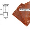
I don't know if there's a "best" way.  One could simply glue it to the Tortoise body and run the wires as needed.  As it turns out that relay has its pins on a 0.1" grid pattern (2.54mm and 5.08mm apart).  So you could use so-called project board which has drilled holes on a 0.1" grid and copper pads to solder the pins for a secure mount.  You would probably mount 2 or 3 relays on one board to share 12V DC wiring.  The project boards are relatively inexpensive - maybe $1 for the size shown.

relay on tenth inch grid


3) I bought a dozen of those blue harnesses (don't know the exact name) so I do not have to solder to the Tortoise itself. The two DC 12 volt Walworts shown in Option #2 seem the best for me to handle. Don't know, however, where the latched relay would fit into the circuit in that diagram.

As it turns out if you want dual-control you need to use the Option 1 method with the DPDT latching relay performing the polarity-reversing duty of the DPDT switch in the Tortoise instructions.  So you only need a single 12V DC wall-wart.  I will draw a diagram once I catch up to your "new goals".

4) I don't how I would wire to use either the DCS/AIU or the panel switch? For example, if the panel switch was set to green "straight," could I throw it to red "curved" with the AIU? If I did so, would there be confusion with the panel switch showing "green?"

Correct.  For planning purposes it's best to separate the indicator (red-green LEDs) function from the switch function.  If it turns out you find a switch which integrates the LED, that's great but you don't want to put the cart before the horse.  This requires a bit of background plus a twist somewhat unique to the Tortoise.  Background: illuminated switches come in two styles.  One style has the light slaved to the position of the switch...so for example the light is always ON (or one color) when the lever is up, and the light is always OFF (or the other color) when the lever is down.  The other style has an isolated light or lights that simply come to terminals on the switch and the user is responsible for activating lights accordingly.  Obviously this latter style is what you want in the Tortoise situation with multiple controllers capable of setting the turnout direction.

The Tortoise also has an interesting property that allows you to hook up a bi-color (2-pin) LED inline with one of the two wires going to it.  With no additional components (no resistor required) one or the other color LED (e.g., red or green) will turn on depending on the latching relay position (set or reset).  It's a very useful feature that simplifies wiring.  This is shown in the rightmost #4 circuit of the Tortoise instruction diagram.  Again, once we are on the same page I can draw a detailed diagram.

And, as fate would have it, many illuminated toggle switches have bi-color LEDs inside with the 2-pins coming to terminals on the switch.  So if you can find a suitable (ON)-OFF-(ON) style switch with an internal bi-color red/green LED, you can simply wire the 2-pins inline with the Tortoise wiring. 

I realize that an illuminated toggle switch means only having to drill one hole for both the switch and the indicator.  And, yes, they are really cool looking.  But I'm guessing you'll have a hard time, or require a fat wallet, to find a suitable (ON)-OFF-(ON) illuminated switch with an internal isolated (not slaved) bi-color LED.  In any event, if you can see your way to drilling two holes (one for switch, one for indicator) there are many 2-pin bi-color LEDs in the standard 3mm and 5mm diameters...say, 25-50 cents each.  I think one of the guys commented he uses green-yellow (rather than red-green) bi-color LEDs on his panel.  Again, more options if you can drill a 2nd hole. 

bicolor led 3mm 5mm

Attachments

Images (2)
  • relay on tenth inch grid
  • bicolor led 3mm 5mm

image

Sooooooooooo, to have dual control, both the switch on the panel AND the AIU ports would be wired to the same latched relay terminals for any given turnout and, thus, either would work at any time?

is it possible to use the DCS remote to activate a turnout and also have the corresponding LED on the panel show the changed status? Ayyyyyyyyyyy

Attachments

Images (1)
  • image
Last edited by Scrapiron Scher
Scrapiron Scher posted:

...

Sooooooooooo, to have dual control, both the switch on the panel AND the AIU ports would be wired to the same latched relay terminals for any given turnout and, thus, either would work at any time?

Correct.  This is shown in the diagram below where the orange and blue wires from the panel switch and the AIU port are tied together.  The diagram also shows the use of basic momentary pushbutton switches wired into effectively the (ON)-OFF-(ON) configuration.  In fact, you could have tri-control with an (ON)-OFF-(ON) switch located at the switch itself to control it a third way.

is it possible to use the DCS remote to activate a turnout and also have the corresponding LED on the panel show the changed status? Ayyyyyyyyyyy

 Yes.  As shown in the Tortoise instructions, a 2-pin bi-color LED (or two different colored LEDs wired back-to-back in opposition) can be wired inline with one of the two wires going to the Tortoise.  This LED(s) can be mounted on the control panel with the switches.  The LED can be in the panel switch itself if you are so lucky as to find an (ON)-OFF-(ON) illuminated switch with an internal bi-color LED.

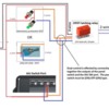
tortoise dual control

More detail is needed to show how to connect the 10-pins of the DPDT latching.  The point of this the diagram is to get your arms around the various components to plan where the various elements can be located or co-located.  Obviously the control panel switches will be mounted near each other.  But maybe mounting more than 1 latching relay on a project board can save some wiring.  For planning purposes, the orange and blue control wires to the latching relay and the 2 wires to the Tortoise can be thin wire as very little current flows thru them...AWG 26 would be fine. 

Attachments

Images (1)
  • tortoise dual control

As a resource for anyone trying this at home, I figure the biggest wiring hassle is with the DPDT latching relay...particularly attaching wires to the somewhat tiny pins (all 10 of them ).   No doubt there are others but Azatrax makes a 12V DC Latching Relay on a circuit board with screw-terminal connectors and corner mounting holes.  

azatrax dpdt latching relay module

They show the Tortoise application though you must make external connections for the so-called cross-connect or criss-cross wiring for motor polarity reversal.  A bit more costly than a $2 bare DPDT latching relay, but to each his own.


Attachments

Images (1)
  • azatrax dpdt latching relay module
Last edited by stan2004

Stan2004,

Decision #1: The small orange DPDT latching relay is barely more than 1/2" long and there is no way I will wire that.

Decision #2: The DPDT latching relay above at $13.75 is out of the question. When the smoke clears I will have  dozens of $40 switch machines.

Decision #3: I will use the AIU Accessory ports to do some/all switch activation

Decision #4: As I understand it I can activate the Tortoises from a panel with the push-on switch without a latching relay, yes? If so, that is my option for the front of the layout and/or the interior where the steam yard will be.

So it is written, so it shall be.

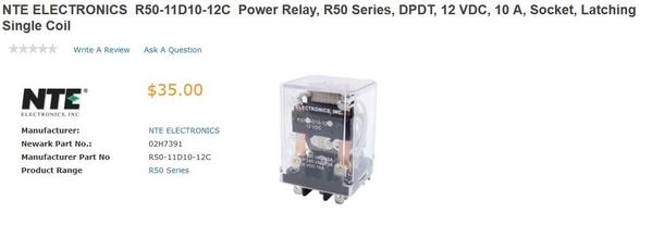
Understood; that Kemet latching relay is indeed a tiny part.  BTW, I looked up the MTH-recommended DPDT latching relay (NTE 50) and found it for $35 at Newark.  Wow!  Is that where you came up with $35 for a latching DPDT relay to control a Tortoise???

nte r50 35 dollar latching relay

OK.  If you go the SPDT route which is essentially a ON-ON type (no center-off), you can only have 1 controller per switch.  So, yes, you can use just an AIU Accessory Port which has ON-ON functionality to control a Tortoise using Option 2 and two 12V DC power supplies wired as shown in the Tortoise instruction.

Then, separately, for those switches under panel-only control, you could use basic ON-ON SPDT switches for less than $2... such as (from vendor suggested by Laidoffsick):

spdt on-on

You can still use a bi-color LED connected inline to one of the Tortoise wires for indication.  And if you can find a suitable ON-ON SPDT switch with a built-in bi-color LED you could then drill just one hole in the panel.  The wiring would be as shown in Option 2 of the Tortoise instructions using two 12V DC power supplies ($2 wall-warts).  If you need specific wiring instructions, let me know exactly which switches you plan to use and I will sketch something.

I'd have to do some head-scratching but if there's still interest in controlling each Tortoise from the control panel OR (not AND) the AIU, there might be a way.  In other words you would choose which method is active (using a switch and/or an AIU Accessory Port) and then that method would be in effect.  So one method or the other at any given time. 

Attachments

Images (2)
  • nte r50 35 dollar latching relay
  • spdt on-on
Last edited by stan2004
Scrapiron Scher posted:

Stan2004,

Decision #1: The small orange DPDT latching relay is barely more than 1/2" long and there is no way I will wire that.

Decision #2: The DPDT latching relay above at $13.75 is out of the question. When the smoke clears I will have  dozens of $40 switch machines.

Decision #3: I will use the AIU Accessory ports to do some/all switch activation  Part of the (Latching relay) discussion was related to the AIU, which most likely only has momentary operation.  The Latching relay allows for the AIU momentary to become a permanent On (required for the Tortoise switch).  You may want to look at the Lionel SC-2 or other Lionel switch control (ASC) components that have a permanent on position v.s. the momentary.  Most could be programmed either way, momentary or permanent on.  Foggy head could be wrong on the AIU, not familiar with this device.  Somewhere in the AIU specification there should be information. 

Part of the problem of using a permanent on system like this (Tortoise Switch control) fed by two or more push button sources is,  each permanent on has to be in the same position. Momentary (auto return to off) works better.  Momentary or several momentaries  to a (one) latching relay solves the problem.   

Decision #4: As I understand it I can activate the Tortoises from a panel with the push-on switch without a latching relay, yes?  Yes, back to using the On/On Double Pole Double Throw (Cross over) switch, and one power supply, the wiring is not all that difficult.  Diagram #1.   If so, that is my option for the front of the layout and/or the interior where the steam yard will be.

So it is written, so it shall be.

There are LED lights that can be added to the existing circuitry at 12 volts that would do a nice job of indication.  These LED usually have a voltage dropping resistor attached. 

Just thought I'd muddy the water a bit more.

Best wishes, Mike CT.


Last edited by Mike CT

The accessory ports on the AIU are always on/off . This what I use. I use ON for diverging and OFF for normal. This way when ever the system shuts down for end of session or breaker trips, upon power up all turnouts return to normal or no train can hit another. I also set up routes. In the accessory ports this is called scenes. I also have the little switch lanterns installed for a signal indication.
Clem 

my 2 cents if your walking around layout already why not use a DPDT toggle switch and wire in a bipolar led at same location? its simple its easy to do all the soldering of the wires and can be done on your workbench.

radio shack used to sell some small plastic project boxes 3"x2'x1" these are perfect for installing into your fascia on layout as they are recessed so are flush with fascia so you don't knock into them the boxes are

drill-able to mount a dpdt mini toggle switch as well as a bipolar led all in one box you mount the dpdt switch inside the recessed area of this box so the throw lever is inside the box thus you won't catch clothing on the levers as you walk by! I used them on my layout and they will hold 4 dpdt mini toggle switches as most say here at times try the kiss method.

and lastly if you have a bunch of switches do you really want to have to remember what number to push or find the switches route number ?

my best advice is get a track turnout a dpdt switch a dc power supply some 20-22 gauge wire a soldering iron and solder and the bipolar led and wire it all up once you have completed it and it all works correctly you will feel more comfortable doing all the others. a side note connect all wires to a terminal strip in case a dpdt switch or the led goes bad so you can remove only the offending component.

hope this encourages you to try wiring a switch in the open and if you get discouraged walk away for awhile sometimes doing so the light bulb in ones head turns on and gives you the answer needed to complete the task.

Mike, Stan, Clem, Doug, and STPAUL, and, of course, all of the others in the thread who have held my hand through the thicket of electronics. This will end up being good for me because the more I learn, the better the railroad will operate.

I am getting closer to starting this project because of all the great help here on the Forum. Many thanks to all of you and now it is just finding the right toggles, getting colored LEDs as indicators, making the panels, wiring up the AIU/Accessory ports and additional controls and I am an electrician.

Add Reply

Post

OGR Publishing, Inc., 1310 Eastside Centre Ct, Suite 6, Mountain Home, AR 72653
800-980-OGRR (6477)
www.ogaugerr.com

×
×
×
×
Link copied to your clipboard.
×
×