Stan2004,
Thanks for posting the great Youtube Video link. I took your video & cued it closer to the sparking segment. Click on the link below & it'll take you there. Might save folks some time.
Copter


|
|
So in theory if I hook up a 9 Leds in a parallel wont it just be enough? im confused because I used the LED calculator and it said if I hook up 32 Leds in parallel and each take 3.2 volts, I would only need a 20 ohms resistor.
As for the train interior, I was going to remove the incandescent blubs and just put in like 3 white Leds to make it look more brighter and prototypical. Last question, what did you use the cut the track? Thanks again!
Not sure what you mean by 9 LEDs in parallel being "enough". Enough for what?
As for 32 LEDs in parallel, I can't imagine any subway car holding that many LEDs! If you have 32 LEDs each drawing 20mA @ 3.2V, that's a whopping 0.64 Amps of current. A 20 ohm resistor would drop 12.8 Volts but in doing so would become quite the heater; Power = Volts x Current = 12.8 V x 0.64 Amps = 8.2 Watts. You'd need, say, a 10 Watt resistor which would probably melt something in the car. That's a lot of wasted heat considering that the LEDs themselves would only be consuming 3.2V x 0.64 Amps = 2 Watts. When a circuit draws this much current, you would use other techniques (instead of a resistor) to control the current/voltage into the array of LEDs.
If by removing bulbs you mean to somehow insert 3 3mm LEDs (plus resistor) in each location where there's presently a bulb, then OK. You'll have to experiment a bit since the 3mm LEDs you mentioned have relatively narrow beams (about 30 degree) while an bulb projects in all directions. If you search the forums for LED passenger car lighting you'll see dozens of threads on the virtues of so-called LED strip lights which run at about 10-12VDC. These are nice because they have wide-angle projection for more uniform illumination
I cut the track using a metal-blade bandsaw. As mentioned earlier I tried to cut just the outer-rail with a hand hack-saw but couldn't get the right angle or orientation...so ended up slicing the trackbed itself to get to the rail.
Opps, I meant 32 Leds to light up the "Subway" Part of my layout. As for the train, I will simply experiment with the 3 LEDs as you have said. I will probably use 1.8mm for the subway LED lights. A parallel layout looks like this
So I guess one Lionel CW-80 cant power 32 1.8mm Leds?
I have heard of LED strips also but im not sure how much resistance I will need for a particular strip of LED
Not sparking, Just to illuminate it to give it a nyc feel like this
https://ogrforum.ogaugerr.com/f...ineImage/true/s5.jpg
did they buy the IC chips or they made it them selves? Curious cause if not ill just have to fiddle around with the extra resistors then
For the constant-on tunnel illumination with 32 (or whatever many) LEDs, I recommend a DC-DC converter module. Otherwise, as discussed above, when starting from a "high" voltage like 18 V and dropping (via resistor) down to 3V, most of your power is going up as heat in the resistor. A DC-DC converter module uses switching circuits to more efficiently convert the power from one voltage to another so you don't waste power as much power.

Search eBay for "LM2596 module" and you'll see these for 99 cents and that includes shipping! It's an extremely good value. You can buy versions that have a bridge rectifier already installed on-board ("LM2596 AC module") but they are more expensive considering you can buy a bridge rectifier for $1 or so on eBay (any bridge rated for at least, say, 2 Amps and 100V).
So you apply AC from your CW and adjust the module to put out some lower voltage like, say, 3.5V to drive a parallel string of 32 or however many LEDs. In this case the resistor will be a much smaller value so the power it wastes as heat will be much smaller. If you have an unused 9V, 12V or whatever wall-adapter with DC output, you can skip the bridge rectifier as you already have DC. You will need a voltmeter to adjust the output voltage but as I was advising a guy in another thread you don't need a fancy meter and Harbor Freight Tool stores if you have them in your area give these away free (with coupon) shown here being used to adjust the module output to 3.0V which is what he wanted to drive a string of a parallel LEDs.

Speaking of parallel LEDs, this reminds me of another freebie I picked up at Harbor Freight - a small 4.5V operated LED worklight that has 24 parallel LEDs.

All those white LEDs are wired up in parallel just as you're planning to do...and note they use a 1.5 ohm resistor. But this is, in part, because they are starting from about 4.5V (3 1.5V batteries). If you choose to use a DC-DC module where you can precisely set the output voltage (the voltage output is regulated so you set-it-and-forget-it), you really don't need a resistor at all if you are driving all like LEDs.


All the stuff being done on OGR is with purchased IC chips (generally inexpensive at, say, 50 cents each). The LED for Dummies thread below started off as a simple "for dummies" thread but morphed into a smorgasbord of ideas about everything under the sun including comparing LED strips vs. individual LED (as you are considering). You can get a flavor for the kinds of IC chips being used and determine for yourself if you want to go there.
I must say, Thank you stan for all the information you provided! you taught me almost a semester worth of information at my college. So Change of plans, Heres my Idea, this is for the constant LED illumination (32 in the subway)
I get any sort of DC 5V or 12V wall adapter laying around my house, Strip the wires, Screw them into the LM2596 (The one I see on ebay has a built in voltimeter) I also noticed it has a USB port..Any reason to why it has it?
http://i.ebayimg.com/00/s/NjAw...OxyMt5TJ8Gu/$_12.JPG
After wards I set the volts to say 3.2V output, and then from the output of LM2596 I just add the wires to the output and simply do the parallel set up I was talking about, and since its already at 3.2v, I wont have to use any resistors on it.
I dont think ive asked this, But I do plan on using DCS in the future, But whats the point of getting an inductor?
As for the LED Strips, Ill look further into the thread you have provided me.
Thanks again for all your help Stan, Once I recieve my LEDs and resistors I ordered Ill post some pictures here if I get them working correctly.
This will be on the test so...![]()
I hooked 12V DC to a LM2596 modules w/voltmeter to the worklight LED array of 24 bypassing the resistor to directly drive 24 parallel white LEDs (5mm diameter).

You will probably get similar results and will probably find you can operate closer to 3.0V. If you're a student, here's that sharp diode-junction "knee" or hockey-stick on the V-I curve in action which is the first curve they always show in the chapter on semiconductors. That is, note the small changes in voltage having an outsized effect on current going from 2.8 to 3.0 to 3.2 Volts. For example, going from 2.8V to 3.0V (delta of 0.2V) causes the incremental current per LED to increase about 7 mA. Use Ohm's law and you get the dynamic resistance of the LED at that operating point...much smaller than the average resistance of the LED. Hmm, I hope they teach you about dynamic resistance and load-line curves!
The big win with switch-mode regulators is conversion efficiency. So at 3V, the 24 LEDs pull 0.3 Amps or ~0.9 Watts. At that output voltage, the 12V input current was 85 mA or ~1.0 Watt. So the efficiency (power out/in) = 90% which is very good for this type of power converter. Actually a little power is being consumed by the voltmeter circuit but can be ignored for this example. If you used the resistor method, the current in and out is the same. So for the same 0.9 Watts out, the input power would be 12V * 0.3 Amps = 3.6 Watts. The conversion efficiency would be 25% which is not so good as 75% of the energy is wasted as heat.
I have no idea why there's a USB connector on your module. I found an eBay listing that looks like your module and one photo shows the USB connected with the voltmeter at 5.0V. So perhaps this is meant to be a USB charger...though it seems pretty risky to require a user to set it to 5.0V before using it as a charger?! Anyway that's my guess.
WRT to DCS signaling, the inductor isolates the impedance (not resistance) of the capacitor from the track voltage. The DCS signal rides on (in class they'll say "super-imposed on") the low-frequency 60 Hz track voltage and is hi-frequency in the kHz-MHz range. A capacitor's impedance is inversely proportional to frequency so it tends to load down the DCS signal. An inductor's impedance is proportional to frequency so by placing it between the track and the circuit, it demotes the loading while still allowing the power signal to reach the load.
Separately, your tunnel photo shows lights on each side of the track. Rather than a single long string of 32 LEDs, run two strings of 16 each (or whatever) from the converter output. This cuts the max current running down each string in half which is beneficial for voltage drop effects as well as wire heating though with the current levels involved you probably won't see any effect.

So how about If I don't use a capacitor?
If you're referring to the effect on DCS signaling, then you don't need the inductor. The problem for LED lighting is you will see flicker. Incandescent bulbs kind-of sort-of demote the flicker effect since there's a filament time-constant where the bulb brightness decays (albeit quickly) when voltage is removed. The common wisdom has been that since the inductor cost is negligible relative to the effort to open up a car, re-wire, add LEDs, etc., why not just throw in the inductor even if you don't use DCS today.
If you're referring to the effect on DCS signaling, then you don't need the inductor. The problem for LED lighting is you will see flicker. Incandescent bulbs kind-of sort-of demote the flicker effect since there's a filament time-constant where the bulb brightness decays (albeit quickly) when voltage is removed. The common wisdom has been that since the inductor cost is negligible relative to the effort to open up a car, re-wire, add LEDs, etc., why not just throw in the inductor even if you don't use DCS today.
Guess Ill have to order some capacitors and inductors. what should be the F and the Volts on them? Does it matter if I get a strong capacitor or strong inductor (I.e Holds in a larger amount of charge)
As shown earlier, MTH uses a single 47uF, 35V capacitor for the 2 red marker LEDs in a passenger car. As you add more LEDs (such as converting the interior bulbs to LEDs), more capacitance is needed as there is more current drawn during the dropouts. Everyone's situation is a bit different wrt how clean you keep your track, tolerance for flicker in the first place, number of turnouts, etc., but I'd say the typical values that the guys use when there are a bunch of LEDs would be 220 uF, 35V (or 50V).
The inductor used for DCS in passenger cars is 22 uH, 1/2 Watt.
Now in class they talk about energy storage in an inductor and capacitor. But in this case the inductor is used for its complex-impedance to block hi-frequency signals, not for its energy storage. Your textbook tells you the stored energy (in Joules) for an L (in Henries) or C (in Farads) is 1/2 * L * I^2 and 1/2 * C * V^2 respectively. Seems about the same right? Well, let's look at some real-world numbers for a subway car. Let's say the current flowing to drive the LEDs is 50 mA total. And the voltage available to charge the cap is 18V. A 22 uH inductor with 50 mA flowing stores only 27 nanoJoules of energy. A 220uF cap charged to 18V stores 35 milliJoules of energy. The cap stores 1 million times more energy.
Well I Just ordered the capacitors and inductors on Ebay. Its gonna take about 2 weeks for my LEDs to come since there coming from China. By then I should start setting everything up
As shown earlier, MTH uses a single 47uF, 35V capacitor for the 2 red marker LEDs in a passenger car. As you add more LEDs (such as converting the interior bulbs to LEDs), more capacitance is needed as there is more current drawn during the dropouts. Everyone's situation is a bit different wrt how clean you keep your track, tolerance for flicker in the first place, number of turnouts, etc., but I'd say the typical values that the guys use when there are a bunch of LEDs would be 220 uF, 35V (or 50V).
The inductor used for DCS in passenger cars is 22 uH, 1/2 Watt.
Now in class they talk about energy storage in an inductor and capacitor. But in this case the inductor is used for its complex-impedance to block hi-frequency signals, not for its energy storage. Your textbook tells you the stored energy (in Joules) for an L (in Henries) or C (in Farads) is 1/2 * L * I^2 and 1/2 * C * V^2 respectively. Seems about the same right? Well, let's look at some real-world numbers for a subway car. Let's say the current flowing to drive the LEDs is 50 mA total. And the voltage available to charge the cap is 18V. A 22 uH inductor with 50 mA flowing stores only 27 nanoJoules of energy. A 220uF cap charged to 18V stores 35 milliJoules of energy. The cap stores 1 million times more energy.
Sorry Stan but I got a question, You said before that when you put in the diode to the middle rail, It will reduce the voltage by half, are you sure this is correct? Ive read about voltage drop but i haven't read a topic that says a Diode will reduce the voltage by half
No worries. For model train electronics there a two relevant characteristics of a diode. One is they conduct current in one direction which effects AC to DC conversion. The other is they induce a voltage drop of about 0.7V. Note that there are interesting applications for diodes in communications for shifting frequencies of signals or switching RF signals but we're talking model trains.
For the sparking application, by inserting a single diode as shown earlier, the current only flows on half of the AC line cycle. Look up "half-wave rectification" in your textbook. Then, because voltage is only available to the LED half the time, the effective voltage is cut in half. IF instead of a single diode you used a bridge rectifier, then current could flow on both halves of the AC line cycle and the voltage would not be cut in half. This would be "full-wave rectification".
In the sparking application, there is NO capacitor shown. If you inserted a capacitor after the diode, this would store energy during the intervals when there would have been no available voltage. So during the half-cycle when the diode could supply current to the LED, it would also charge up the capacitor. During the other half-cycle when the diode was "cut-off", the capacitor would step in and supply current to the LED.
You might need to think about this for a bit but you don't want to install capacitor in a sparking circuit for 2 reasons. First, if you are using track power, then the capacitor means you need to also add that inductor to deal with DCS signaling. Second, by leaving out the capacitor, the voltage available to the LED is more "choppy" and variable (the capacitor smooths the voltage). You want this somewhat random-like change in brightness in the LED for sparking. Note that the inventor even used a "blinking" LED presumably to make the sparking more random or hence more life-like (in my opinion).
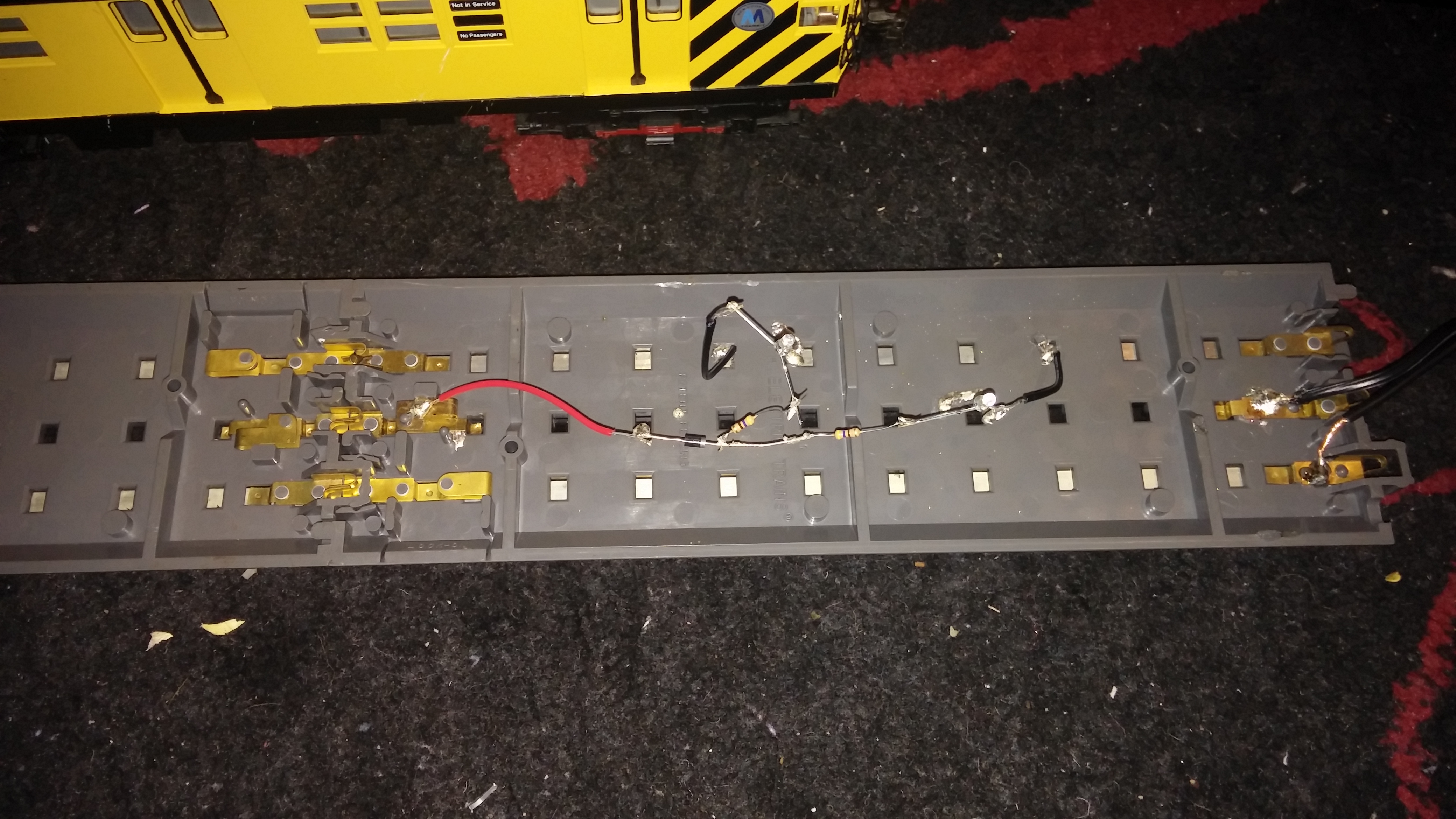
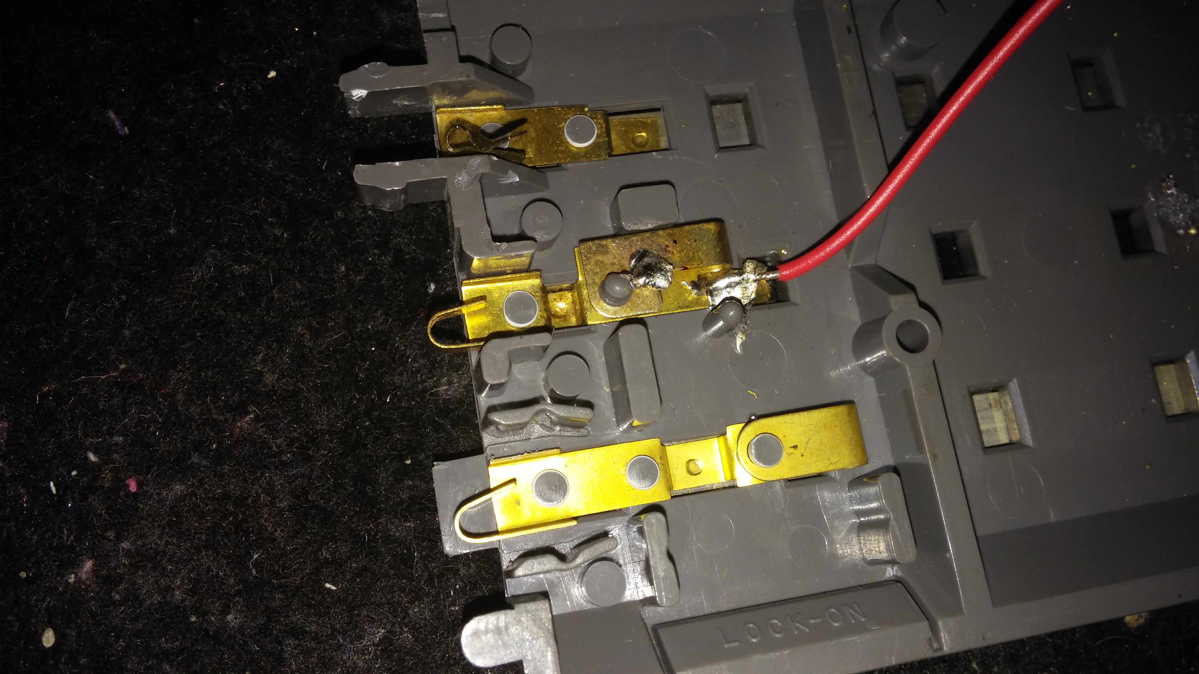
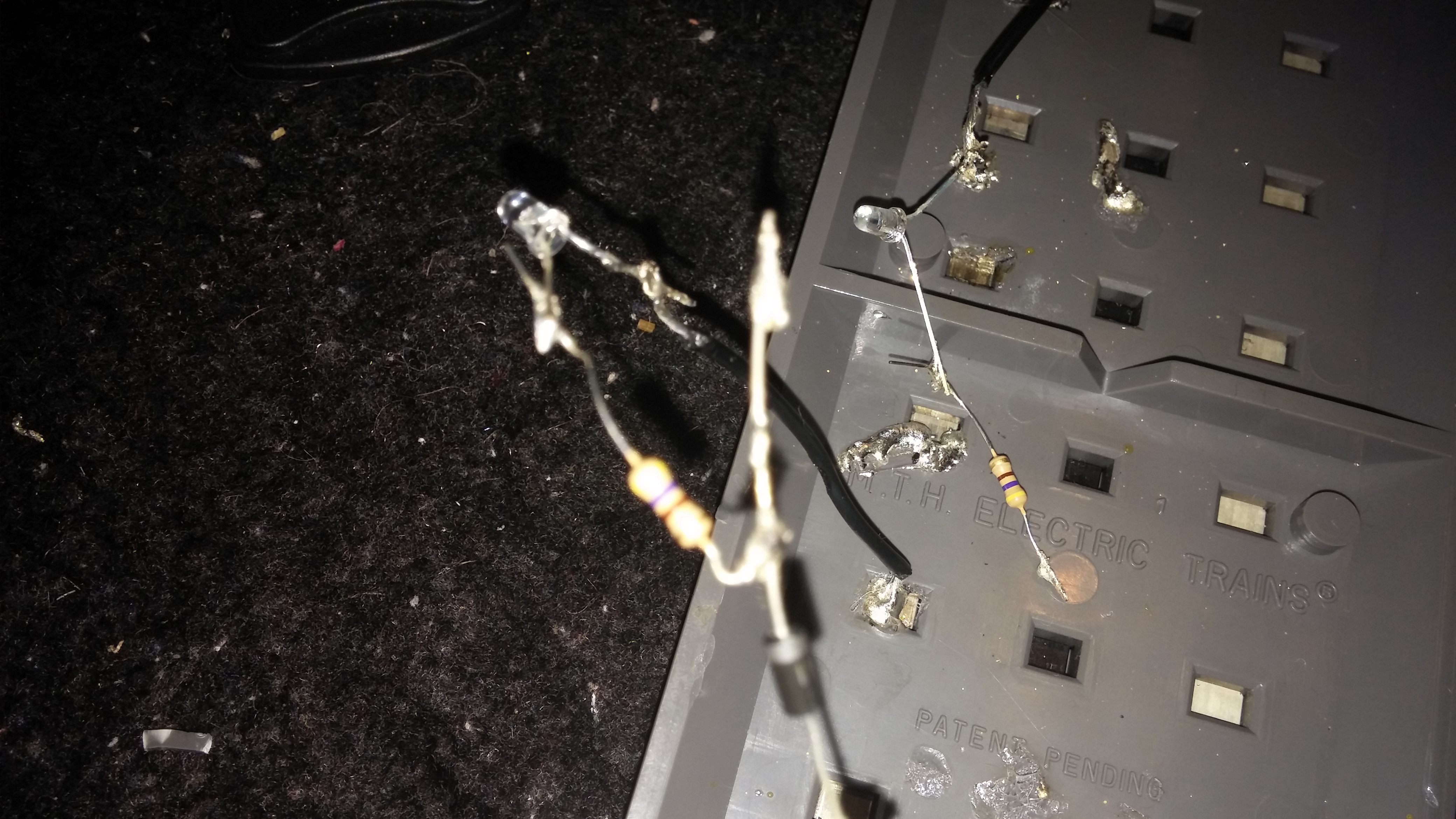
ahhh..Bad news it failed! The LEDs did not light up. I tried to resolder everything moved the hot wire but it still failed. Im not sure why. Im using the 1N4007 1A 1000V Rectifier Diode DO-41. important thing note is I did not cut the rails because I dont have a hacksaw handy, instead I just bent one of the connectors out of place. When I put power and the train on it the LEDs did not light up! I put it another LED with a 1k ohm resistor and still it did not work. Im using the Lionel CW-80 and mth reatrax.
 20140430_180213 by [url=https://www.flickr.com/people/32235547@N02/]killa134528[/url], on Flickr
 20140430_172452 by [url=https://www.flickr.com/people/32235547@N02/]killa134528[/url], on Flickr
 20140430_180055 by [url=https://www.flickr.com/people/32235547@N02/]killa134528[/url], on Flickr
 20140430_180105 by [url=https://www.flickr.com/people/32235547@N02/]killa134528[/url], on Flickr
 20140430_180114 by [url=https://www.flickr.com/people/32235547@N02/]killa134528[/url], on Flickr
 20140430_180155 by [url=https://www.flickr.com/people/32235547@N02/]killa134528[/url], on Flickr
You should be able to run a "red" and "black" wire direct from the CW to your red and black wire and the LED should light up. Also, do you have a voltmeter handy?
unfortunately no, I do plan on getting one in the future, Although it could be posible that its poor soildering connectoins im not sure. does the model of the diode effect it?
You should be able to run a "red" and "black" wire direct from the CW to your red and black wire and the LED should light up. Also, do you have a voltmeter handy?
I ordered a voltimeter, hopefully it will come soon so I can ese what the issue. I will probabl trying tfixing this again idk how though
Access to this requires an OGR Forum Supporting Membership
