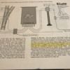
I am about to construct a small control board for a switching yard. I would like to install Bi color common cathode design LED's to indicate turnout position. I have searched Circuiton, Youtube , as well as the OGR forum and have become familiar but would appreciate more input. 3mm sized LEDs and a 1000 ohm resister wired in series seems the common choice. Any suggestions on the resister size/ LED pair would help clear the air. I would prefer a bi color LED over a seperate green/red combo. I am using the Tortoise "SMAIL" version to throw the turnout. SMAIL is not the exact same as the Tortoise wiring I'm learning. It uses DCC control as well as a manual momentary SPDT switch to actuate the motor and throw the points if desired. The SMAILS I've installed work well. I believe the LED should be wired through spots 5,6,7 on the SMAIL, as on AN 6000-2, I've included. My frog power comes off position #4. Position 2 and 3 are unused. I believe spot 5 is +12VDC input from my seperate accessory bus, spot 6 and 7 attach to the 2 anodes(long wires) of the LED and the cathode(short wire) returns to -12VDC. Thanks in advance
Jim


