Hello again...

Background:

I've had a few good discussions with folks (stan2004, gunrunnerjohn,...others...) about the best way to do block occupancy detection for signal lights and whatever else needs to be controlled.  Several people suggested using current sensing (magnetic-inductive or Hall effect) but as many people pointed out on the forum... this doesn't work for long trains that don't draw current in their cars/caboose, or LED lit trains where the current is tiny.

Alternatively use of an isolated rail with a relay is pretty good but sometimes small trains can struggle because it isn't necessary touching both rails all the time, and when the track is AC-powered you can't really put a diode across the coil to shunt the reverse current when it releases, and when you touch the track you can get a zap.

Both of these are actually pretty satisfactory solutions, but I wanted to challenge myself to see if I could come up with a circuit that

1. Has no moving parts

2. Has both outer rails grounded all the time (at least at 60 Hz power and for DCS/TMCC signals)

3. Doesn't interfere with DCS/TMCC operation


This is probably overkill, but it's a good circuit design problem to practice those analog fundamentals....

============================

UHF Block Train Detector

============================

UHF_switch

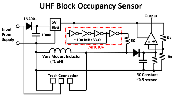
Okay so the idea is conceptually simple. We exploit reactance (imaginary resistance)  to provide different grounding conditions at different frequencies. We do this by putting a small inductor of about 1uH across the two outer rails of the track, meaning they are basically connected at low frequencies, while still open circuit at high frequencies. We then use the high-frequency conditions to trigger the signal lights or whatever else.


Quick Frequency Analysis:

So at 60 Hz (track power) the impedance between the two outer rails is X = 6.28 * 60 * 1uH = 0.003j ohm  (basically a short) so no problem here.

At the highest frequency we need to worry about (DCS's 3rd harmonic at 11 MHz) its X = 6.28 * 11M * 1uH = 69j which is still a much lower impedance than the engines are at this frequency (about 400 ohms). We actually measured this on a VNA and posted it here  (Train Impedance). Note: we consider the 3rd harmonic and not the fundamental because we want the DCS waveform to be nice and square looking (square waveforms have dominant energy in harmonics 1 and 3) otherwise the receiver in the engine will struggle to detect the spread codes properly. 

Since this is like 1/5th the train impedance it's still providing an adequate ground for the DCS signal. Keep in mind the other rail connected directly (not through the inductor) is still in parallel with this too. Just to make sure I checked anyways, and the DCS signal can go through a 1uH inductor without issue. To test this I just put the inductor in series with the TIU output and ran a the train and did the built-in signal test....


 =============

Implementation:

==============

Rectifier:

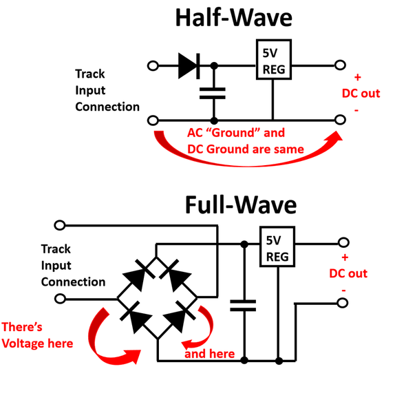
Right so the first thing we want is for the circuits to run of the track power so we don't need extra power lines (which are unpleasant to add to a layout). While normally you would use a full wave rectifier, for this particular application a half-wave rectifier is a better choice... becasue it has the advantage of ground that is common with the input. This is good to know for many many train projects.

If you use a full wave rectifier your common node is neither track terminal, but in fact something in-between, while in half-wave version... one of the track terminals can act as "ground" to all your DC circuitry.

It goes like this...

rectifier

UHF portion:

Next we use a 74HCT04 which is just a CMOS logic gate chip with 6 inverters on it (does anyone else call them "not" gates?). So we form a basic ring oscillator with 3 of the gates, then use a 4th one as an output buffer. The manufacturing variation of the chip along with soldering will set the exact frequency, but it should be in the range of 100 MHz (well beyond DCS or TMCC or anything else train). It's important to do this setup well out of band so the block sensor doesn't jam or interfere with control signals. Both TMCC and DCS use matched filters in the controllers and engine, so they will filter out this 100 MHz signal and not let it go into the control circuits for the trains.

Okay so basically we take the oscillator output and form a voltage divider between the inductor and a 50 ohm resistor in series with the buffer output. When there's no train the impedance at 100 MHz is quite high:

X = 6.28 * 100 MHz * 1uH = 628 ohms

so the voltage divider output is roughly  628/(628+50) = 92% of the 5V / 100 MHz waveform.

When the train comes into the block, the impedance of the inductor drops due to the parallel short, and so the AC voltage at the node falls dramatically (I think in my prototype, the oscillator actually stalls from too much loading).

Next we just used a diode envelope detector to turn the AC waveform into a rectified DC format. We set the time constant of the envelope detector to about 0.5 seconds as a means of debouncing, so if the train looses contact with either rail momentarily it won't affect the output, and only 3-time constants or longer disconnects (so like 1.5s) will actually change the signal light or whatever you're controlling. Finally we use a comparator stage (LF358n in my case becasue it supports single rail operation) to detect if the envelope detector is up or down. Since the peak voltage at the env-detector output is about 4.5V with no train and below 100mV with train, the swing at the comparator input is quite dramatic and so the reference for the comparator doesn't have to be terribly precise. I just went with 2 resistors as a divider to give you 5V/2 = 2.5V (mid-point between supply and gnd).


=============

Testing

=============

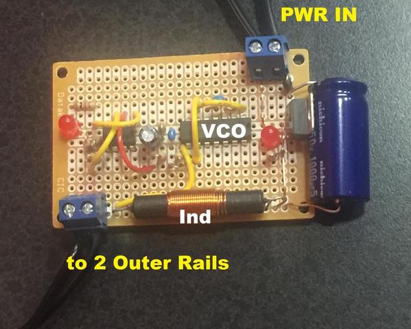
We went ahead and made a simple prototype board to try out the design concept and in testing the circuit works quite well. I don't have a TMCC setup, but my DCS engine doesn't notice it at all (checked by running a train, and with the built in signal test).

Train_dect


Here's a short video showing the setup with a piece of test track. In this case I don't even have the center rail wired and I am just experimenting with a boxcar (it doesn't have a center-rail pickup). First when I hit it with the DMM you can see the resistance across the two outer rails is basically 0 ohm (just wire resistances). Then when I drop the boxcar there (hard to do while holding my phone)... the train detector lights up... Anyways pretty-much everything costs about $16 from digikey.

Again maybe a little overkill, but analog circuit design is fun. I'm thinking this may end up being a project for like a 1st or 2nd year undergraduate analog class in the near future....


~Adrian


Attachments

Images (3)
  • UHF_switch
  • rectifier
  • Train_dect
Videos (1)
UHF_switch
Last edited by Adrian!
Original Post

Replies sorted oldest to newest

Interesting concept, and I doubt it would affect the TMCC signal as the outside rail is only half the signal.  The DCS interference would be more of a concern to me.  I'm presuming that inductor has to carry the full track current based on the statement that the rails are not insulated when using this technique.  For longer insulated rail sections, you may want to drop in another inductor at the far end to connect the rails.

Adrian! posted:

Alternatively use of an isolated rail with a relay is pretty good but sometimes small trains can struggle because it isn't necessary touching both rails all the time, and when the track is AC-powered you can't really put a diode across the coil to shunt the reverse current when it releases, and when you touch the track you can get a zap.

One point on the insulated rail and relay is that when train cars are on the rails, both rails are powered if any wheel is on the non-insulated rail.

PLCProf posted:

Looks good. I don't think it is overkill at all.

I am going to breadboard this as well. I would be curious about possible transmission line effects; in particular 1/2 and 1/4 wave circuit lengths might prove interesting. 


I like exactly what gunrunnerjohn suggested. Split 1uH into 2 inductors of 2uH each (or more even), and make sure they aren't placed at a VSWR minimum.  Lamda/4 is about 0.75 meters so it should make options. Also, I think if one inductor is on the PCB it forces a voltage maximum to exist at whatever point you tap the track (provided the track-board wire is short).

The other thing I didn't think about is the layout maybe radiating. I guess this is okay as long as you fall in the 88-108 MHz range (like a wireless mic). I don't think a 74HC04 is going to produce enough power to upset the FCC. Maybe need some thought about adjacent section blocks capturing the signal too...


I'll be interested in seeing the results, and especially any findings regarding effect on DCS signal.  This might be an interesting alternative to the insulated rail sensor that Gunnerjohn Electronics has been discussing in another thread.  As noted above, there are some locomotives that have issues when one outside rail is insulated.

For your enjoyment.

Understanding The FCC Part 15 Regulations for Low Power, Non-Licensed Transmitters

Home-Built Transmitters that are Not for Sale
Hobbyists, inventors and other parties that design and build Part 15 transmitters with
no intention of ever marketing them may construct and operate up to five such
transmitters for their own personal use without having to obtain FCC equipment
authorization. If possible, these transmitters should be tested for compliance with the
Commission's rules. If such testing is not practicable, their designers and builders are
required to employ good engineering practices in order to ensure compliance with the
Part 15 standards.

There's obviously a whole lot more in the document.

Last edited by gunrunnerjohn
Adrian! posted:
... but I wanted to challenge myself to see if I could come up with a circuit that ...


2. Has both outer rails grounded all the time (at least at 60 Hz power and for DCS/TMCC signals)

...

I like the concept and this is the kind of thinking the hobby needs!

What excited me by the thread title was an alternative to the insulated-rail section which can be a hassle to install, retro-fit, fabricate, etc.  But as I understand it this is an improvement to the insulated-rail method as it provides "ground" power all the time to the insulated outer rail.  What I don't know is if this is an operating issue with layouts.  That is, if there is no train on the insulated-rail section, then do you really need for the insulated-outer rail to have "ground" power available to it?  When the train finally does come along and one or more wheel axles short the outer rails, then it seems this shorting puts "ground" power to the insulated outer rail at a time when it could be of use (to provide a better ground connection to other powered cars/engines on the section).

I'm curious if you considered or are considering some kind of high-frequency occupancy detection that does not require the insulated rail section;  I think this is the holy grail of occupancy detection.  Other techniques using magnets, optics, or even grandkids have their issues.  As I understand it, prototype occupancy detectors also sense changes in electrical parameters - and are localized working over a distance of a thousand feet or whatever.  By way of analogy, it seems with your RF expertise and access to modeling/simulation design tools and instruments, there ought to be a way to have the wheel axles change the high-frequency impedance between the two outer-rails on a localized basis (within, say, 6 inches of the shorting wheel axle) - even if it shifts the frequency just a few percent.  Your UHF idea is nice and simple since it is basically an on/off detector.  But with low cost components such as tuned UHF resonators and demodulators I think you might be able to finally eliminate the gap in the outer rail.

Adrian! posted:
PLCProf posted:

Looks good. I don't think it is overkill at all.

I am going to breadboard this as well. I would be curious about possible transmission line effects; in particular 1/2 and 1/4 wave circuit lengths might prove interesting. 


I like exactly what gunrunnerjohn suggested. Split 1uH into 2 inductors of 2uH each (or more even), and make sure they aren't placed at a VSWR minimum.  Lamda/4 is about 0.75 meters so it should make options. Also, I think if one inductor is on the PCB it forces a voltage maximum to exist at whatever point you tap the track (provided the track-board wire is short).

The other thing I didn't think about is the layout maybe radiating. I guess this is okay as long as you fall in the 88-108 MHz range (like a wireless mic). I don't think a 74HC04 is going to produce enough power to upset the FCC. Maybe need some thought about adjacent section blocks capturing the signal too...


Hi Adrian-

Spent a few hours today fiddling with this.

Didn't have a 74HCT04, so I used a 74HC04, same thing with CMOS-compatible inputs instead of TTL. Oscillator frequency is about 25 MHz, but there is plenty of third harmonic. Did you look at your oscillator output? I would be curious to know if you are really running at 100+ MHz.

I wound a 1 uH air-core coil, mounted the coil on the protoboard and ran a few feet of non-descript wire to a 10 foot length of Realtrax. Left the center rail unconnected.

It sorta works. It was necessary to replace the fixed divider on the comparator with a "sensitivity" pot, the few feet of wire running to the track markedly reduced the effectiveness of the unit. As expected, wave effects are noted, as I roll a car down the track you can find a dead spot. With no cars on the track, running my finger along either rail finds spots that will activate the output.

Time permitting, I will experiment some more. If I can manage to build a "pancake" inductor that will handle the track current, I may try to put the "RF" stuff in the bottom of a Fastrack section and locate the PS and comparator remotely. I was also wondering about using a "wobbly" oscillator to eliminate the wave effects.

Exactly what are you using for an inductor?

Thanks again for all your help!


I'm curious if you considered or are considering some kind of high-frequency occupancy detection that does not require the insulated rail section;  I think this is the holy grail of occupancy detection.  Other techniques using magnets, optics, or even grandkids have their issues.  As I understand it, prototype occupancy detectors also sense changes in electrical parameters - and are localized working over a distance of a thousand feet or whatever.  By way of analogy, it seems with your RF expertise and access to modeling/simulation design tools and instruments, there ought to be a way to have the wheel axles change the high-frequency impedance between the two outer-rails on a localized basis (within, say, 6 inches of the shorting wheel axle) - even if it shifts the frequency just a few percent.  Your UHF idea is nice and simple since it is basically an on/off detector.  But with low cost components such as tuned UHF resonators and demodulators I think you might be able to finally eliminate the gap in the outer rail.

I was thinking about this a lot actually. The way they check for discontinuities on transmission lines is to send a pulse down the line and look at reflections from discontinuities. The issue is a train layout is only a few 10s of feet so you would need like 10^-9 time resolution which is GS/s range, meaning expensive scopes, expensive ADCs and such. Also when you start adding switches to the layout, I'm not sure this really makes sense...

PLCProf posted:

Hi Adrian-

Spent a few hours today fiddling with this.

Didn't have a 74HCT04, so I used a 74HC04, same thing with CMOS-compatible inputs instead of TTL. Oscillator frequency is about 25 MHz, but there is plenty of third harmonic. Did you look at your oscillator output? I would be curious to know if you are really running at 100+ MHz.

I wound a 1 uH air-core coil, mounted the coil on the protoboard and ran a few feet of non-descript wire to a 10 foot length of Realtrax. Left the center rail unconnected.

It sorta works. It was necessary to replace the fixed divider on the comparator with a "sensitivity" pot, the few feet of wire running to the track markedly reduced the effectiveness of the unit. As expected, wave effects are noted, as I roll a car down the track you can find a dead spot. With no cars on the track, running my finger along either rail finds spots that will activate the output.

Time permitting, I will experiment some more. If I can manage to build a "pancake" inductor that will handle the track current, I may try to put the "RF" stuff in the bottom of a Fastrack section and locate the PS and comparator remotely. I was also wondering about using a "wobbly" oscillator to eliminate the wave effects.

Exactly what are you using for an inductor?

Thanks again for all your help!


Hey, The oscillator is running about 91 MHz in mine. It's sort of hard to tell because the scope probe loads the oscillator. Even if you look at the buffer output, there is some miller effect of the scope-probe cap so the frequency you observe isn't exact. I've always found the various CMOS parts can vary a lot depending on what package the are in (PDIP SDIP, ...) since the oscillator speed is driven entirely by parasitic cap. In general the 4000 series (like the 4049) tend to be a little faster than 74HCTs.

I wouldn't spend hours chasing it down.... I'd bet 25 MHz is probably still fine and far enough away from DCS and other control signals. Are you soldering or bread-boarding? (sometimes when you breadboard above 10 MHz) fun stuff happens. The inductor on my board is one of those small ones wound on carboard with a ferrite screw (except I took the screw away). 

My setup didn't see those wave effects, but I'm sure it can happen, I mean it makes perfect sense (wavelength, Zo, TL discontinuity). The wire to the track is acting inductive making the "short" the train induces across the inductor less and less like a short. If you keep the two wires twisted together tight it should reduce the inductance a lot and help sensitivity since the current is the same....

Your idea is great actually..... what if we "FM modulated" our detector?... Since we are just detecting the oscillator's amplitude, any type of constant envelope modulation effect should be okay. So if we just put a varactor or something similar at a low modulation rate (like maybe 10-100 KHz) and had an FM modulation depth of like 70-to-100 MHz or something, the standing-wave null would be avoided. For every position on the track there would be at least some of the sweep where there is no null. I may go back and try this out later...


Last edited by Adrian!
Jan posted:

Does each block require a transmitter?  Or will one do for the entire layout?  If it can be done with only one transmitter the there would less likely be a prob;em with the FCC.

Jan

Hey,

It's not really meant to be a transmitter, just a sensor... I'm sure it does radiate a little bit, and the way it works for now, we do need one sensor per block.

Add Reply

Post

OGR Publishing, Inc., 1310 Eastside Centre Ct, Suite 6, Mountain Home, AR 72653
800-980-OGRR (6477)
www.ogaugerr.com

×
×
×
×
Link copied to your clipboard.
×
×