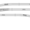
I have Greenberg's wiring book but it does not help me with this one.  Given the attached photo which is a portion of my upcoming layout, I need to know where to put the power drops.  Normally I would just put a feed every 6 or 10 feet.   The turnouts will all be manual throws.  I am not sure where I can locate the power drops or where they "must be" given the turnouts.  I have heard things like "you have to power all 3 legs of the turnout but am not totally sure what that means.  Perhaps it just means there has to be power on each leg coming off the turnout?


I googled this and could find nothing.


Attachments

Images (1)
  • ogrpostwiring
Original Post

Replies sorted oldest to newest

TurtleLinez-


Ross Custom Switches posted a suggested wiring scheme for the #11 switch here:you can use this diagram for the regular #11 switch as well as the #11 wye switch. My recommendation would be to wire the switches per Ross' diagram, then connect the third rail and common feeder wires every 6-10 feet. If you opt for electrical blocks, you would have to adjust your wiring scheme to permit the blocks to be turned on and off accordingly.


-John

Last edited by AcelaNYP
Originally Posted by AcelaNYP:

TurtleLinez-


Ross Custom Switches posted a suggested wiring scheme for the #11 switch here:you can use this diagram for the regular #11 switch as well as the #11 wye switch. My recommendation would be to wire the switches per Ross' diagram, then connect the third rail and common feeder wires every 6-10 feet. If you opt for electrical blocks, you would have to adjust your wiring scheme to permit the blocks to be turned on and off accordingly.


-John

Thanks John, I saw this but it seems this is for electric throw as opposed to manual?

Originally Posted by AcelaNYP:

TurtleLinez-


The Ross diagram applies to both manual and remote switches, as it details how to connect wires to power the rails. The switch machine (on remote switches) only moves the switch points and has no impact on how the rails are powered.


-John

What is he trying to show with the "P" on the left versus the one on the right?  The one on the right means connect all 3.  The left one with the A means?

Last edited by TurtleLinez

TurtleLinez-


If I'm reading it right, the "P" is for Power (center rails) and the "G" is for ground (outer rails). "A", "B" and "C" refer to the power rails for the straight route, diverging route, and switch throat; if all three are wired together then the entire switch gets powered. If you wanted to create isolated blocks on one or both switch legs, then you would not connect "A" with "B" or "C".


-John

Last edited by AcelaNYP

TurtleLinez-


Just two actually - the outer rails are for the common (return) to the transformer.


What Ross is suggesting is simply connect jumper wires (~1" long) to the points marked "P" so that all center rails on the switch are powered. If you needed to run feeder wires to the switch from the transformer/power bus, only one set would be needed.


-John

John C, my 4-way is wired for non-derailing as shown in my bottom photo of the #8 turnouts joining parallel tracks.  I did not cut into my 4-Way tracks. 


I did drill the correct size wiring holes into the tracks for power wiring and non-derailing control wiring.  The non-derailing control wiring at the V tracks is 22 gauge for the short run to the terminal strip (under the table).


The "DZ-1000 Wiring for Automatic Non-Derailing Operation" does show the turnout V tracks cut which is not needed with the long V control rails.  Just be sure the two rails in the V are insulated from each other with hot glue or other.

Originally Posted by pandw:

Susan:


Why would you need the Green 1's if each turnout has insulating pins?


Tony

With Ross turnouts from the factory, the 2 rails that form that V are frequently touching.  The Hot glue (Green 1's) keeps the 2 rails separated so one rail switches to diverging route and other rail switches to straight route.


At the bottom of the Z-Stuff Non-Derailing Instructions page,  those tracks are shown with a cut instead of using the whole rail with hot glue.

AWESOME!  I had no idea how it could be done and the only thing I kept thinking was that I would have to cut the rail on the turnout.  I'm very hesitant to cut a rail on any turnout.  THANK YOU!!!!
 
Originally Posted by Susan Deats:

John C, my 4-way is wired for non-derailing as shown in my bottom photo of the #8 turnouts joining parallel tracks.  I did not cut into my 4-Way tracks. 


I did drill the correct size wiring holes into the tracks for power wiring and non-derailing control wiring.  The non-derailing control wiring at the V tracks is 22 gauge for the short run to the terminal strip (under the table).


The "DZ-1000 Wiring for Automatic Non-Derailing Operation" does show the turnout V tracks cut which is not needed with the long V control rails.  Just be sure the two rails in the V are insulated from each other with hot glue or other.


Post

OGR Publishing, Inc., 1310 Eastside Centre Ct, Suite 6, Mountain Home, AR 72653
800-980-OGRR (6477)
www.ogaugerr.com

×
×
×
×
Link copied to your clipboard.
×
×