


RTR12, I sent you an email, hope you like what I sent. You probably won't use it, but it might give you some ideas. ![]()
Thanks Dave, I saw it, but just getting ready to go upstairs...almost bedtime. I will take a better look tomorrow and get back to you via email. And a Big Thanks for doing that, I really appreciate it.
RD posted:...David I've gone back and re-read your last few posts and the suggestions are so right on its like you are reading my mind. Running the reverse loop around the outside of the upper curve and down the backstretch is a super idea and the extra room needed to do this is well worth the outcome. Also I believe it was you who mentioned making the second level the O elevation and raising the top level and turntable/roundhouse area...another hit as far as I am concerned. I'm still a bit hesitant about all the double-slip switches .. but that can be worked out.. bottom line I love your ideas and the plan you put together if there is a drawback it's the Atlas track.... I would like to see if it could work with Ross turnouts and gargraves flex... from what Ive learned the last few days about flex track it seems like the ticket. What do you think??
RD,
There's no doubt the plan I drew up can be reworked with Ross/GG track. In fact, there are a few places on the plan where I've already used Ross turnouts on curves, since Ross makes O-80 and O-96 turnouts that were easy to insert into the respective O-81 and O-99 curves.
This week is very hectic for me, so I don't think I'll have the time to do any kind of conversion justice. But it should be relatively straightforward. The biggest challenge is gonna be related to the different geometry between the Ross #4 double-slips and the Atlas-O #5 double-slips. If you go Ross, then the turnouts connected to the Ross double-slips will also need to be #4 turnouts. A quick look at things in RR-Track gave me the impression that you'd need 2.25" fitter pieces of track connecting the Ross turnouts with the double-slips in order to maintain 4.5" track spacing. That's all very doable. However, the Ross #4's are noticeably smaller/sharper than the Atlas-O #5 turnouts, which are actually much closer to Ross #6 turnouts in length (according to RR-Track). And trains hitting those #4's coming off the concentric curves could enter somewhat of an undesirable S-curve due to the sharper angle of the #4 turnouts. If Ross made a #6 double-slip to match their #6 turnouts, this wouldn't be as much of an issue. But I guess their thinking was the double-slip usage is limited more for yard track routing rather than out on the mainline.
I placed the double-slip turnouts pretty much wherever I saw them in the original HO plan. I understand your "reluctance" to use them though... hence my cautionary note earlier in this thread. They do provide a dramatic WOW-factor when viewed up close from trackside. However, you REALLY need to ensure your locomotives will track smoothly through the various different routes of trackwork without stalling or shorting. I do recall Atlas-O used the double-slips on their big York demo layout about 10 years ago, and I never saw any problems when I watched trains go through them. But honestly, they weren't using EVERY route available with the double-slips during their demo's.
If you ultimately decide you don't NEED the routing flexibility the double-slips provide, then you could probably get away with using Ross #6 turnouts (where I've used Atlas-O #5's) to provide more basic cross-over functionality between parallel tracks. And those #6's should provide trouble-free performance for all of the equipment you plan to run. Just watch out for center rail power gap issues if you run small locomotives. But that issue can be solved with relays. You just need to decide how much you're gonna lose (operationally speaking) by not allowing trains to easily go directly from track #1 to track #3, or directly from track #2 to track #4 in that area just above the TT in the plan.
Hope that helps.
David
Sorry, RD, but I'm not giving up just yet and you can delete my posts if you want to. Or ask me to and I'll be happy to oblige. ![]()
Now we're back to Ross/GG after you beat me up about it at least twice. ![]() That's okay though, I can deal, so on to the main reason for this post.
That's okay though, I can deal, so on to the main reason for this post.
David said: "Now here's the "new way of thinking" I was referring to earlier in my post: namely, the green track that's largely hidden remains at elevation level ZERO throughout much of the plan. It's the OTHER track (in blue and purple) that is either elevated (blue track) or lowered (purple) to adjust ."
And you responded with "Also I believe it was you who mentioned making the second level the O elevation and raising the top level and turntable/roundhouse area...another hit as far as I am concerned."
So, lets say Level 2, the green track, is set to elevation 0". That means Level 2, the purple track, only has to decline 6" (or 7") to the point where they cross each other. If you run both purple tracks around the outside, that point can be quite far and the decline quite acceptable.
Now, that's great for Level 3, but what about Level 1? The green tracks are directly below the turnouts outlined in blue. That means if the green tracks are at 0", the blue tracks have to rise to 6" at that point or trains won't clear. If you start the incline somewhere on the green tracks, that means the blue tracks then have to rise 6" before they get to the tracks outlined in red. I don't care what level is elevation 0", there has to be 6" of separation at both the blue and red points. You simply cannot get there if all the green track is at elevation 0". There is not enough space for the tracks to rise 6" between the blue and red points. Things work in the original photo because it has a full 40' of O scale space to work with and the lower loops are drawn tighter.
Now, if you consider the green tracks in the red outline to be elevation 0" and the blue tracks above them to be elevation 6", then the rest of the green tracks can go down a portion of the total grade and the blue tracks can go up the rest. Unfortunately, then the purple tracks have to go down further because there still has to be 6" of separation where the green tracks cross over them.
If you and David don't understand this now, then I'm the one who surrenders, I don't know how to explain it any better. ![]()

Attachments
Images (1)
"" And MikeCT has shown that GG flextrack can be bent to these curve sizes fairly easily using his techniques.""
"" but then I wouldn't hesitate to use Ross/GG after seeing MikeCT's examples, if that's the look I preferred. ""
Dave, I noticed you refered to Mike CT's examples a couple of times in your posts. I have seen Mikes wiring work and he is in my opinion a true craftsman if not an artist. If his examples of bending flextrack lead to the same type results then I ask you please put up a link to these examples.
Again I appreciate all the help from you and Carl and David ... I know my lack of experiance and basic knowledge of scale track systems caused some frustration and that I regret. I have made a firm decision to use Ross/Gargraves flextrak.. further research has led me to believe that choice will give the most flexability.
I plan to have the room finished by the middle of May .. after that comes benchwork .. track and wiring...etc..and away we go!!!
""Sorry, RD, but I'm not giving up just yet and you can delete my posts if you want to. Or ask me to and I'll be happy to oblige""
Dave, One more time.. I appreciate your help and advice. You obviously know more about the rrt program and the various scale track systems than I do and that knowledge has been very helpful if sometimes confusing. That's on me...
Good post guys. Great designs.
DoubleDAZ posted:...If you and David don't understand this now, then I'm the one who surrenders, I don't know how to explain it any better.
...
DAZ, with all due respects, then I think it's time for you to surrender on that point. ![]() You're completely missing the point that I tried to make earlier -- namely once you start adjusting track heights with open grid framework vs. the plywood platform mentality, then you actually have very few places where ANY track is completely level.
You're completely missing the point that I tried to make earlier -- namely once you start adjusting track heights with open grid framework vs. the plywood platform mentality, then you actually have very few places where ANY track is completely level.
In the last plan I posted, V1B (which didn't have the grades finalized), I'll say that generally speaking the TT area and the bridge over to the passenger station yard area will likely be completely "level". Aside from that, a large portion of this layout will have grades that rise and fall in order to provide the appropriate clearances. And the grades are nowhere near the severity that you've represented. In addition, there's absolutely nothing wrong about turnouts being on a modest grade. We've seen that many times on popular model railroads that have been featured in magazines as well as right here on the forum.
We (once again) seem to be exerting more unproductive energy on these issues you're hung up on, than actually moving the ball forward. We've maintained ALL ALONG that there would be compromises necessary to shrink the layout from the full 20x40 O-scale rendition. No surprises there. Yet despite all of that, I've given RD a version of this compressed layout that is quite "build-able" given his space requirements. If RD decides he wants to go Ross/Gargraves instead of Atlas-O, even that's not a show-stopper. It's just that he may then decide it's in his best interested to stick with basic turnout crossovers rather than the more intricate Atlas-O design with double-slip switches. It's not as if people haven't used the Ross/Gargraves combo on spectacular layouts before. It's been done all the time. And this one will be no different.
David
Yes,
Attachments
Images (1)

Here's a thread with a couple of techniques, including Mike's.
https://ogrforum.ogaugerr.com/t...78#70693071009750278
I know you appreciate the help, but you're already talking bench work and I don't know about David, but I think the question of grades will certainly have an impact on that. I like your enthusiasm, I wish I had more, but once you start cutting wood and driving screws, things get more difficult to change.
And it doesn't have anything to do with software expertise, David probably has me beat there with RRT, but the geometry between the 3 levels in this compressed version just isn't adding up for me. I see you and David talking in terms of 3 "levels" whereas I see 3 "places" that need 6" of separation and they're all dependent on a 4th place, the tunnels. Regardless of the implication that I think in terms of tables, the tunnels are my elevation 0" and the other levels go up/down from there. I tend to use all positive values though because I measure from the floor up and I'm sensitive to the viewing level. When I do a design, I do a full design, including bench work, so elevation 0" might actually be elevation 43". That might not make sense to you or David, but that's what I see when I look at a finished layout, so that's what I try to reproduce in software.
Well, David, then I leave it to you to finish......whenever you find the time. I'll be back later to delete all my posts, so they don't gum up the thread. I'll leave the one with the link to the techniques for bending GarGraves, RD is going to need it if he pursues this using Ross/GG. I sincerely hope you prove me wrong and if you do, I'll grab a copy of the file for future reference. Either way, I wish RD the best of luck.
DoubleDAZ posted:Well, David, then I leave it to you to finish......whenever you find the time. ... I sincerely hope you prove me wrong and if you do, I'll grab a copy of the file for future reference. Either way, I wish RD the best of luck.
DAZ, it was really NEVER about proving you wrong, per se. Rather it was showing RD there was indeed a way to bring his compressed track plan closer to reality in O-Gauge -- albeit with a few compromises. As we know, we seldom can have our cake and eat it to. But since you were insisting to raise doubt that the plan could accommodate clearances, I took a half-hour this afternoon to fine-tune the grades. I did this VERY quickly, but it sure seems like everything worked out as I envisioned in the original concept.
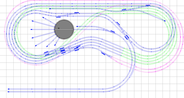
So here ya go... V1C which has the grades finalized, with grades maxing out around 3.1% (give or take), and in some areas grades are well below 2%. That was using 6" clearances. If RD felt better using 7" clearances, he could probably maintain similar grades by bumping the plan out a foot or so in both dimensions. But we've already done that once for added functionality, and I don't think it's worth doing it again solely for this reason.
Now this plan still uses Atlas-O track, as I just don't have the time this week to do a full-blown conversion to Ross/Gargraves. And RD still needs to decide if he wants to go with basic Ross #6 cross-overs vs. the combination Ross #4 turnouts and Ross #4double-slips. (Honestly, my recommendation at this point would be to use the Ross #6's on the mainline tracks above the TT area, if he wants Ross/Gargraves... and stick with double-slips in the passenger yard area.)
The V1C diagram doesn't look that much different from V1B, but the RRT file will have the updated information with grades and track heights:

RD, at this point, the plan is yours to have fun with. Enjoy the ride!!!
All the best,
David
Attachments
Images (1)
Files (1)
"" I'll be back later to delete all my posts, so they don't gum up the thread. ""
Dave I really wish you wouldn't... they are full of valuable information.
Well, David, you proved me wrong, so I stand corrected and I'll eat a box of Crows Black Licorice Drops as a penance.
FWIW, I did find 2 grades that weren't set (both on the right side, one on an inside green track and the other on the outside blue track) and there's only 5.5" clearance at the tunnel, but those are minor. I'd correct them, but I'm not going to post yet another version and further confuse things.
Not that it matters, but I also figured out where my thinking went wrong. It wasn't so much about flat vs open grid, it was more about looking at the return loops as reversing loops and thinking they needed to be level. But it was mostly about your insistence that Level 2 be at elevation zero and the other levels would go up and down from there (see my earlier quote of your statement). Obviously, either you misstated or I misunderstood what that meant. And I had a note here to try 0" at the tunnel, 2" at the turnouts and -4" beneath, but frustration overcame my desire to do so.
I still don't like RRT's 3D view with terrain following, but it does show the elevation of the mains and they look fairly nice and even. I have to take another stab at our taxes tomorrow to validate the first run and I'm traveling for the next 2 weeks starting Tuesday, so I don't have the time to play with conversion to Ross/GG either.

Attachments
Images (1)
RD posted:"" I'll be back later to delete all my posts, so they don't gum up the thread. ""
Dave I really wish you wouldn't... they are full of valuable information.
I've been told they're confusing, but it's your thread, so I'll leave them.
This is taking shape, but I am still having difficulty envisioning what will be available for the viewer. David's rendition manages to get the purple line to the outside for most of it. The green line appears that it would be lost. I guess that one will have to be hidden with access points only.
Of course, the blue line is all visible with some terrain features(cliffs) due to the two grades going to the aisle. Then, perhaps cliffs down to the purple. Purple would need some tweaking to keep out on the edge.
So, where to leave it open, close it in and such? RD, were they any other views in the plan book to help one get a side view?
It looks like the under tables have center openings, but that would be a given to access the top level wiring.
How should it be sceniced to present the most action for the viewer? This is an island walk-around layout with 360° of viewing angles.
We restored a 3 level layout with a hidden connecting helix between the three layers. When we finally grasped how it would look with the scenery repaired, our first thought was that the trains were hidden too much. This was easy layers, as the track radius decreased as it elevated. it's 11' x 17'.
Just trying to stir some thought on the final presentation as the track is coming under control.
Attachments
Images (2)


Videos (1)

Ok, just to help, I roughly followed the shapes of David's levels and set the decks at the same heights to perhaps provide a perspective. I stretched the purple level out to expose as much of the end curves and the long side run.
I can't do angled graphics in SCARM yet, so the levels are constant. The track would grade of course.
It may help visualize the sub-roadbed shapes.
Attachments
Images (3)


Well, here's one last revision for the night, V1D. Four changes worth noting:
- I've added a curved cross-over using Ross curved turnouts on the curve connecting the TT/Roundhouse/EngineService area with the Passenger Yard Tracks. I intended to do that earlier, since it allows easier access to the TT from essentially ANY of the passenger tracks. A minor tweak, but it will buy back LOTS in terms of operational flexibility.
- I moved the entire TT/Roundhouse area slightly to the right to avoid potential track clearance issues beneath the TT. Even as it is, the TT underframing may still impact the hidden green tracks slightly. If this happens to be the case in real life (you'll know immediately once you see your turntable), then the entire diagonal stretch of hidden track on both lower levels (green and purple) can be shifted to the left to avoid any clearance issues with the TT framing. There's plenty of room to shift those tracks to the left without changing any of the concentric circle trackage on the far right and far left of the layout. Alternatively, the TT can still be moved a few inches to the right. However, you'll need to plan exactly how many stalls you'd want for your Roundhouse, and then ensure you have proper clearance between the back of the roundhouse and the blue mainline tracks behind it. Even if you decide on just a simple 3-stall roundhouse so things aren't too crowded, it'll still be an impressive structure.
- I bumped the purple track out a few inches on the far right-hand side of the layout (still within the overall 15x26 footprint), so it is now essentially "visible" for that entire stretch. However, you may want to intersperse stretches of visible track with short, hidden tunnels along the way for interesting scenic effects. In fact, that may be your best ticket along that outer purple track... and you'll still have roughly 28-30" of aisle space between the concentric curves and the passenger yard tracks once you decide on the exact location of the benchwork fascia in that area.
- Lastly, I've added a 4-track hidden staging yard (beneath the passenger yard tracks), which is accessible from the purple return loop. This required some minor tweaking of the blue trackage (i.e., new curve turnout) leading into the purple return loop tunnel from the mainline double-slip.
So here it is, V1D:

For clarity, here's a diagram of just the two lower levels, much of which are hidden.

At this point, RD, I don't think there's really all that much left to do with this plan aside from outlining the aisleways/fascia. Then of course there's the conversion itself to Ross/Gargraves, which I still think will be relatively straightforward once you decide between Ross #6 turnouts on the mainlines vs. the #4's with double-slips. Or perhaps you'll decide to work directly from these files with Atlas-O track! ![]() Either way, this should turn out to be one spectacular layout. Best of luck!!!
Either way, this should turn out to be one spectacular layout. Best of luck!!!
David
Attachments
Images (2)
Files (1)
RD,
David's changes to the purple were perfect. Here are some more enhanced shots of what the layout may look like in the room. I like leaving the yard table legs open, closing the end and using round legs. Then, it's attractive and one can see the trains in yards and look through it. 3/4" with stained edges would look fine.
I closed in the green line. It could be possible to leave the aisle edges open for a view of the green line under everything.
Looking at the original plan document, I am have having trouble visually with the industrial area spurs and the commissary/express freight yard on the large on blue level or top level. They look like appendages that don't belong on a freestanding table.
It appears that it was designed to be against walls.(the plan document notes building flats) If you build yours freestanding, they look really awkward and detract from flow of the layout from the yard side and the end.
I don't think that you would lose a lot of operational value deleting those tracks for the aesthetic improvement of the layout. I propose that they be eliminated.
Perhaps I can get some track on this and show the purple exposed running on a ledge by closing in under the blue level.
Here's some more 3D's.
Attachments
Images (4)


To follow Carl's lead and keep it in RRT, I also added some decking to show the separation of levels. This was done before David posted his V1D version, but I copied the decking over, I just didn't change it for the new hidden yard, etc.
Obviously, David and I have different workflows when it comes to RRT, especially with regard to elevations and 3D displays. Therefore, in order to display all the tracks above RRT's baseboard, I used RRT's "Grade/Elevate Track" feature to globally raise all tracks 9". The lowest track is now 0", the highest is 15", and this didn't change the grade percentages. I should have changed the highest elevation to something closer to 50", so I could have added legs, etc., but I didn't think of it last night, I just wanted to get rid of the negative elevations. BTW, there is a stray straight track in the lower left corner of David's versions. I meant to mention this earlier, but forgot.

Attachments
Images (1)
This is taking shape, but I am still having difficulty envisioning what will be available for the viewer.
Carl the concept is for big city scenery...the open space at the top ..opposite TT/RH area.. skyscrapers .. downtown .. Bill B's tower city .. elevated CTA... a grand plan I know but..aim high right??
David's changes to the purple were perfect. Here are some more enhanced shots of what the layout may look like in the room. I like leaving the yard table legs open, closing the end and using round legs. Then, it's attractive and one can see the trains in yards and look through it. 3/4" with stained edges would look fine.
At this point, RD, I don't think there's really all that much left to do with this plan aside from outlining the aisleways/fascia. Then of course there's the conversion itself to Ross/Gargraves, which I still think will be relatively straightforward once you decide between Ross #6 turnouts on the mainlines vs. the #4's with double-slips. Or perhaps you'll decide to work directly from these files with Atlas-O track! ![]() Either way, this should turn out to be one spectacular layout. Best of luck!!!
Either way, this should turn out to be one spectacular layout. Best of luck!!!
David...Ross #6's it is.. at this point I agree that would be best.. and Carl is right..these last changes you've posted are perfect! ... the pictures Carl posted of the decks and levels are right on..It's like you guys are in my head seeing the same vision .. freaky really how tuned in David and you have been since the start ..
I agree there is little left but some details which will depend on how I place the layout in the room.. I have options.. picture the top boundry of the plan (pass station/yard) as along the long wall in my basement ..opposite that wall is about 18' of open space then the stairs. I can put the passenger station/yard against the long wall so the side with the purple line going down + TT/RH and big city would be what you see as you come down the stairs..or flip it 180 and put the puple line against the wall and the station /yard area is what you see first.. or I can put the station/yard against the wall and bring the layout out of the upper corner of the room on an angle..45 sort of.. this would mean some changes in the way the yard/staging connects to the mainlines but can be done..
These decisions will be worked out in my head as I finish the room prep..but now thanks to you guys I have a plan and a solid vision in my head of what the layout will look like as I move it around the room...I also seem to remember that I have a full set of Ross templates laying around here somwhere that I bought a long time ago to help plan the "dream" layout. Once the room is done I can use the templates to help figure out the benchwork. I sent a copy of ver_1c to my friend Jim Williams to look over what I need to do concerning the miles of wire that will no doubt be under and around .. the journey continues.
Guys, at this point, I'm gonna let RD run with things as he wants. He now has a fairly solid proof-of-concept plan to work with going forward, and there's so much we just don't know in terms of room specifics and his personal preferences.
I think the original plan was designed to have the side of the layout with the passenger station and hidden yard beneath be anchored to a wall. If that can be done with this plan, that would be IDEAL. But again, we have no knowledge of RD's preferences, nor are we familiar with any of the nuances of the room. I think I recall RD saying the entire room is "open" (i.e., no support columns). But whether he intends to have the entire layout in the center of the room vs. anchored to a wall is gonna be his call.
Anchoring the layout to a wall will have the added benefit of incorporating a backdrop that can draw the viewers into the whole scene. And the 2-foot wide yard areas would be ideal for this... then have the larger/wider portion of the layout be where the walk-around capabilities come into play.
As for RR-Track philosophies, I actually do prefer using absolute track heights in my own designs. But this was essentially a proof-of-concept goal, hence the discussion about ZERO elevation and points above and below that. Now that RD has the plan, he can pretty much run with his own preferences of actual layout height, and RR-Track makes it very straightforward to "lift" the layout in this case to RD's preferences.
David
RD, you made your last post while I was typing my last post! ![]() So you've begun to articulate some of the things I was talking about. Sounds like your creative wheels are turning... and that's what it's all about from this point forward. Enjoy the ride, and keep us posted from time to time.
So you've begun to articulate some of the things I was talking about. Sounds like your creative wheels are turning... and that's what it's all about from this point forward. Enjoy the ride, and keep us posted from time to time. ![]()
Best of luck!
David
Quite the layout. How do you propose to access the middle or far ends of the layout? Hatches and ducking under. I am 50 years old and crawling under or on-top of the layout gets old quick. A Middle of the room might alleviate some of your access issues.
Seacoast posted:Quite the layout. How do you propose to access the middle or far ends of the layout? Hatches and ducking under. I am 50 years old and crawling under or on-top of the layout gets old quick. A Middle of the room might alleviate some of your access issues.
Take a look earlier in the thread... RD's room dimensions are roughly 22x35, and the layout footprint is now 15x26. If the passenger/staging yards are anchored to a wall, the big portion of the layout will have walk-around access. So that's a big help right there. That leaves the area that's currently void of track in the plan to be a natural access area. And potentially -- depending on how many turntable tracks RD wants, there's room for another small access hatch near the TT. I just threw a 32" TT (because that was the largest in the RR-Track libraries I had) and filled in the tracks from there. TT's and Roundhouses tend to be VERY overwhelming elements of an O-Gauge layout, so even a 3-stall roundhouse would be impressive. That whole TT and locomotive service area is ripe for tweaking based on personal preferences.
David
"If the passenger/staging yards are anchored to a wall, the big portion of the layout will have walk-around access. So that's a big help right there. That leaves the area that's currently void of track in the plan to be a natural access area."
Being able to walk around the outside of the largest portion of the layout puts all but the TT/RH trackwork in reach. I've been looking at the plan the last couple days with an eye towards bencwork.I think it can be done with nothing wider than 3'.. I'm looking at 3x8 for the average for ease of handling.
"TT's and Roundhouses tend to be VERY overwhelming elements of an O-Gauge layout, so even a 3-stall roundhouse would be impressive. That whole TT and locomotive service area is ripe for tweaking based on personal preferences."
Right you are...again... I have been playing with the idea of moving the whole section to different spots around the plan... just by floping it to the other open space opposite its present spot would change a whole bunch of things the least of which is how trains enter and leave the yard/terminal area.. or.. how about the top end of the yard opposite the passenger terminal.. move it of the main layout completely ... or...
how about moving the the main layout platform so it comes out of the upper left corner of the room on a diagonal.. that woul widen the space at the bottom or right side which the maybe makes room for a runaround track at the end of the station????
my head is spinning with possibilities...![]()
I want to congratulate Dave, David, and Carl on what they accomplished with the design of this layout. I really took a shine to it when RD posted the page.
Jan
Great job guys. I've been checking every so often. The 3d really reflects what a cool plan that is. I wasn't so sure in two dimensional views.
Boo Man posted:... The 3d really reflects what a cool plan that is. I wasn't so sure in two dimensional views.
When it comes to 3D viewing, the "creme de la creme" of model railroading CAD planning software is something I've only recently heard about. It's called 3rdPlanIt by Eldorado Sofware. Given it's capabilities, I wouldn't hesitate a NY-second to spend the $125 for it if I were planning more model train layouts. Heck, I'm so intrigued by its capabilities, I might get it anyway!!! ![]() Or at least play around with the trial version.
Or at least play around with the trial version. ![]() Yes, it's the first piece of software for model railroad layout planning that's given my eyes cause to stray away from RR-Track after all these years. It's THAT impressive.
Yes, it's the first piece of software for model railroad layout planning that's given my eyes cause to stray away from RR-Track after all these years. It's THAT impressive. ![]()
David
Jan posted:I want to congratulate Dave, David, and Carl on what they accomplished with the design of this layout. I really took a shine to it when RD posted the page.
Jan
No way this plan comes together this well or this quickly without their help. The wealth of knowledge and experience here is a very valuable resource to anyone planning a layout. I can't begin to describe how grateful I am for all the help!
I installed the demo version and need some time to go through some of the tutorials to figure out how it works. That will give me something to do during the stops on our trip next week. ![]() I checked the list of track libraries where it shows just GarGraves and Lionel, but found there are more in the program itself.
I checked the list of track libraries where it shows just GarGraves and Lionel, but found there are more in the program itself.
DoubleDAZ posted:I installed the demo version and need some time to go through some of the tutorials to figure out how it works. ...
I wouldn't expect this to be an "overnight" learning curve. Quite the opposite, in fact. With this program, you can work up your entire ROOM with all kinds of details, like where the doors, windows, and backdrops will be -- not to mention the program's ability to import images/photos of virtually anything you'd want to place on your layout. Even the benchwork design can be extremely detailed as well (if you so choose to use it for this level of details). It's one of the best -- if not THE best -- program I've seen for rendering 3D views for our model railroad track plans -- even those with multiple decks. The program is really amazing. But when software is this powerful, it tends to have a lengthy learning curve that improves with practice.
Not my intent to sidetrack RD's track plan discussion with this stuff. It's just that somebody mentioned how the 3D views helped him envision the layout better. And I thought I'd chime in and mention 3rdPlanIt, since it's 3D rendering is really out of this world.
David
Rocky Mountaineer posted:RD, you made your last post while I was typing my last post!
So you've begun to articulate some of the things I was talking about. Sounds like your creative wheels are turning... and that's what it's all about from this point forward. Enjoy the ride, and keep us posted from time to time.
Best of luck!
David
Hi guys,
Following up on Davids request to " keep us posted" I thought I'd do a quick update. It is still full speed ahead with the plan as we left it. The hope of having the room done by May turned out to be a pipe dream. I've been steadily working towards that end but it looks like Santa Fe Jims prediction of end of August/September is a more realistic goal for finishing the room and starting benchwork.... I really want the room to be right before I start messing it up. To that end it is almost empty of all the trains and misc crapola that accumulates over 15 years. Once that happens it's a thorough cleaning...man the dust...new carpeting..track lighting .. tune up the bathroom... exhaust fan etc.. it's going to be comfortable.
I am also really considering a loop around the ceiling ..like Pat Mariano has ..dedicated to the Acela which I will have to do before I start benchwork.... and all this time is being put to good use saving for track.. lumber.. etc. Power and operating systems are covered.. I have aLegacy system and nabbed a like new ZW-L from a fellow forum member at a GREAT price ..also I have a ZW-C along with at least ten 180w bricks and a couple of 135w.... this plus a couple of postwar ZWs, a KW and a TW should handle it.
I have also been toying with the placement of the layout in the room. Because of the open spaces and the way the Station tracks are separated give plenty of options to stack staging tracks and think levels.
So I figure if I finish the room by mid September start benchwork before the holidays I should be well on my way to laying track by the new year. If I get the family to pitch in things could even go quicker....maybe.... that's it for now...
RD,
Good to hear from you.
yes, the preparation and planning do take time. Continue to think through the room prep.
usually one needs to provide some inspiration to get help...
Forum member Seacoast has an interesting ceiling layout and there's the large clear acrylic ceiling layout. I'll add the link when I find it.
Time for the latest news.. I'll be going to my first York next week and bringing my track plan with an eye towards layout building supplies... such as backdrops..benchwork..track..switches & roadbed... turntables/ roundhouses... electronics.. etc.. etc.. etc.. looking for any and all ideas to help put this thing together...
Also looking forward to meeting the folks that have been so helpful here...
A very lovely design! Great work on this!
Question: As the layout fits within a larger space (giving access around the layout), will the yard tracks at the top of the plan actually extend to both the left and the right to use more of the available space, which would otherwise be open? That is, the long dimensions of the room are 35', but the layout only extends 26' - that is nine feet of space at the top wall that could accomodate longer spurs to the left and right. Or are there plans for bookcases or cupboards filling the top wall to the left and right? Or are there doors or other obstructions to prevent extending these spurs? It would be interesting to see the layout plan within the larger room.
Cheers! -Ken
Hi Ken,
It really is a deluxe plan .. but David and Carl and a few others did most of the work!
To answer your questions there is room to move the layout around as I mentioned in an earlier post .. also the way the yard tracks connect to the layout is very flexible and depends on how I position the layout . I also want to leave enough room for a comfortable sitting area with a couple of overstuffed chairs a table or two ..you get the idea.. Somwhere awhile back I made a scale drawing of the room including all doors..windows..poles etc. I'll have to try and find it and scan it in..or I guess I can duplicate it in RRT....
Add Reply
Sign In To Reply

