stan2004 posted:
wrawroacx posted:

... you have the accessory voltage and see you connect one wire to the black wire from the 14 Volts to the 2C, is that correct and the red wire to the Crossing Lights? Also from both diagrams, why do you have to have 2 different options?

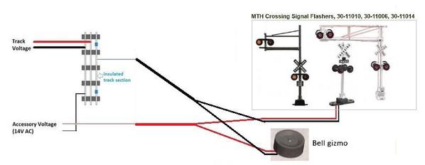
Correct.  In this case, the black wire from Acc Voltage goes to 2C.  Red wire from Acc Voltage goes to the Red wire of Crossing Lights (and to Red wire of Bell if used).

I show options because they are exactly that.  The two methods will behave the same (i.e., are functionally equivalent) but sometimes one method can be simpler - for example requiring less wire length.

Well, not to confuse the issue but I hasten to point out that your question was "can this relay work for...".  In the options category, yet another method for these accessories is to skip the relay all together.

mth crossing stuff no relay method

So while the relay "can" work for those lights, you do not necessarily "need" that relay (or any relay).  This is because these latter accessories are simple OFF or ON accessories with only 2 wires.   The crossing gate is a more complex accessory which is ON and ON and hence needs the relay module to manage the extra wiring (5 wires).

What makes your head spin is there are reasons why you might want to use a relay module even if you don't need one.  That starts to get into subtle differences in how different relay modules are designed and the dialog can become somewhat geeky with a helping of philosophy. 

You need a relay module like Azatrax for the crossing gate.  You can use the relay module for the simpler signals. 


Stan, please email me at  wrawroacx@windstream.net  I have some more questions, but don't want to keep bumping up this post.

Martin Derouin posted:

Can't the flasher with bell, or no bell, be connected to insulated rail,  It is only a straight on or off connection.

Indeed.  We might have been writing at the same time - see my post above.

But to peel another layer of the onion (this stuff can get so complicated it can make a grown man cry!)...

I'd say the first "complaint" that comes up with the direct insulated rail connection method is intermittent triggering from dirty wheels/track contact.  So you can get flickering behavior in the accessory lighting or audible hiccups with the bell module.  Some relay modules suppress this, some better than others. 

Not necessarily for crossing lights which are low-power, but there are accessories that consume quite a chunk of power.  When connecting the accessory directly to the insulated rail, all that power is flowing through the wheel axles.  You might see sparking on the wheels.  In the case of a relay, only the power to activate the relay coil flows through the wheel axles.  It's just my opinion but I like to keep "control" currents low and let relays do the heavy lifting. 

Additionally, the relay method can provide time-delay so the accessory remains activated for 10 seconds (or whatever you set) after the train clears the insulated section.  Perhaps not for guys looking for simple plug-and-play accessory activation but if willing to fiddle with insanely (low) priced relay and electronic modules from eBay you can add all kinds of neat features to make a layout more interesting.  Again, just my opinion.


stan2004 posted:

Upper right of page click on POST then TOPIC pull-down then fill the blanks for title, etc. and you're off to the races!

post topic

So you're missing the CENTER led in the vertical-proceed state.  Post if this is occurring on all 4 heads.  And if practical to separate the wiring, does this occur on each head if that head is the only one connected.


Yes.  Each individual one was doing the same.  I finally figured it out.  My pony wire that went from the signal bridge to the IR controller, was brand new off a spool.  Swapped it out and I'm back in business.  Thank you for all who thought about my problem.  

Non-sequitur:

Understand the white and yellow drives the gate up and down.  Be interesting to find out why it was designed this way.  That is, why not a wire to insulated rail block that drives gate down then automatically up after clearing rail block?  They have board that does the flashing, it couldn't be hard to add up down transistor logic unless motor current draw is alot.  My MTH semaphore is a direct to rail operation with a built in timer raising flag to yellow then green.

Last edited by rrman

Interesting observation.  Another example would be the 3-wire red-green dwarf.  I'm sure someone knows the history of the SPDT contactor plate vs. relay vs. solid-state circuitry to steer lamp power from red to green triggered by an insulated track section.  I think the least expensive off-the-shelf solution in 2017 is about $10!  We have entered the Twilight Zone. 

I've been working off-line with Tom and thought I'd share what I don't recall seeing on OGR. 

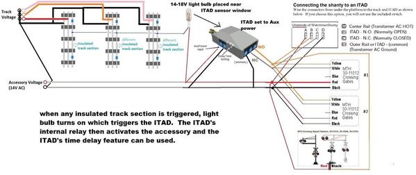
Let's say you've tried the ITAD method but can't get it to work reliably across 2 or 3 parallel tracks.  You go back to the insulated-rail method but wish you had the time-delay feature that ITADs offer.  The time-delay feature also suppresses intermittent noisy wheel/track contact which can flicker signal lights.  You have an ITAD sitting in the drawer gathering dust.

mth realtrax itad and insulated rail multi-track 3 to itad

Dust off the ITAD.  Connect a bulb to turn on when any of the insulated-rail sections is triggered.  Place the bulb near the window of the ITAD.  When the bulb turns on it generates enough Infrared energy to trigger the ITAD (which is looking for Infrared reflections from a passing train).  Hook up your accessories to the relay contacts of the ITAD and you also have the time-delay function!

The diagram shows an MTH Realtrax ITAD which plugs into Realtrax like a lock-on.  But if you power the ITAD from Accessory Voltage you don't need to use Realtrax and can locate the ITAD "anywhere".

So the ITAD is simply being used for its Relay and settable time-delay.  You do need a small light bulb but I figure most guys have these lying around.  If you don't have an MTH Realtrax ITAD they seem to be about $20 shipped on eBay.


Attachments

Images (1)
  • mth realtrax itad and insulated rail multi-track 3 to itad

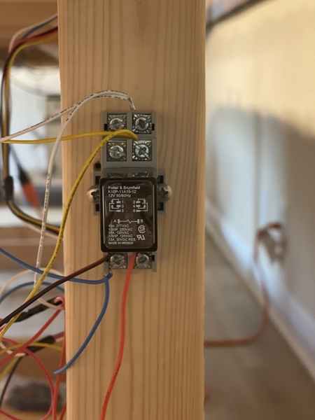
From reading the posts in the above thread, this has been beat to death, but please bear with me.  I’m having trouble getting my MTH crossing gates to work.  They are connected to the 14v posts on my Z4000 and when I touch the blue and yellow wires together, they go up and when I touch the blue and white wires together, they go down and the lights flash.  I’m using a Potter and Brumfield DPDT relay as shown in the photo below. Which wires go to which number?  I had these on a previous layout several years ago and they worked fine.  Thanks in advance for any help.  I’m stumped!  IMG_5673

Attachments

Images (1)
  • IMG_5673

Add Reply

Post

OGR Publishing, Inc., 1310 Eastside Centre Ct, Suite 6, Mountain Home, AR 72653
800-980-OGRR (6477)
www.ogaugerr.com

×
×
×
×
Link copied to your clipboard.
×
×