Used them for years, the tolerance of the LED is amazing. I used the 14v version just because I use them in place I do not use the resistor in.
With all due respect, you have no idea what you're talking about. Tolerance? There is no doubt that an LED will tolerate 25 microamps, it hardly notices it! We making an indicator light, presumably one that will be relatively easy to see in normal room light.
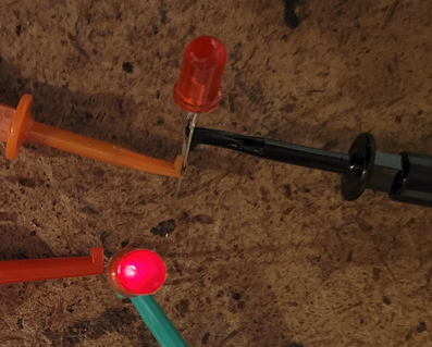
Here's two red LED's both powered from 18VAC, one with a 1K resistor and the other with a 300K resistor. In normal room light, the one looks completely dark, guess which one has the 300K resistor?

So, I turned off the bench lights and the other LED, and sure enough, there is a very dull glow that you can barely see, it is actually lit slightly with 25 microamps.
I'll leave it up to @John H which resistor value he thinks is appropriate for his indicator lights. I'm betting it'll be the one that he can actually tell is lit! 
All I can say is you must have Eagle Night Vision to be able to use that as a pilot light!