
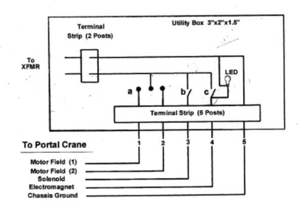
Does anyone have any ideas as to why I can't replace a postwar controller with three simple switches in a project  box?  1) on-off  for the magnet, 2) SPDT maintained contact for the rotate/ lift, and 3)  SPDT center return for the spin/ lift.  Seems I have to open up the one I have every few months and re tension those spring loaded contacts.

Ideas welcome!


Attachments

Original Post

Replies sorted oldest to newest

Great ideas, I plan to do  the indicator  light idea for the magnet and will get it done this week.  However, John, I do have one of  those  timer modules sitting around from a past project.  So I might get elaborate assuming that is working! (No KISS principle here.)

One puzzle I can't figure out, last week I almost bought a "282 controller" on that auction  site. It only had a four  wire conductor cable (instead of five) but the seller claimed  he had sold many without issues.  Could this unit be for the  newer  DC motor version?  It was advertised for a 282 but I can see no way to take one of the  282 or 282r units down from five conductors?

Well, it only took a few  years to complete this project but who is counting. (Did I say I would do it next week?)  Here it is for the record.

Someone sent me this sketch and this is what I used pretty much.  Switch A is a SPDT momentary, B is SPST and I did use a LED indicator for C.   Pictures of the finished product are below.  @Susan Deats and the slsprr information were very useful for tracking down the conntections on the crane to connect the new wire.  I need to get out the Epson label maker now.  BTW, terminal strips will be below the layout.

PS to GRJ: I did not add the timer for the magnet - I fear I failed the classy test on this one.


102_7664102_7665

Attachments

Images (3)
  • mceclip0
  • 102_7664
  • 102_7665

Add Reply

Post

OGR Publishing, Inc., 1310 Eastside Centre Ct, Suite 6, Mountain Home, AR 72653
800-980-OGRR (6477)
www.ogaugerr.com

×
×
×
×
Link copied to your clipboard.
×
×