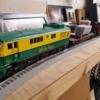
it's looking great!  And now you got me hooked...

I've received 2 fuel tanks from shapeways for the model I'm trying to print.  One uses their default process in plastic, the other uses PLA.  The default process is vastly superior and produced a finish in flat black that to me needs no further hand processing or paint.   The PLA is shiny with striations.   It's fine for perhaps very basic prototyping, and can be less expensive ... (you have to check using their convenient web interface) -- which would be the major motivator for using PLA at this point.

So given that, I've ordered up 3 more pieces in the default plastic process -- they are being printed now.  The first is something that sits about the fuel tank -- the model which I got from elsewhere -- calls it a "fuel gauge" ...  there is one per side.

The other is what I call the platform -- in the model it includes the front, back stairs -- basically the flat bit between the top engine shell and bottom wheel/truck assembly.

The fuel gauges are pretty cheap to print but the platform is pricey.

In the original models the fuel gauges were solid but I hollowed them out -- and platform was 2 pieces but I connected them.  This is because (I believe) the original model is in 1:32 scale & so the parts don't fit in the printers -- but in 1:48 the pieces fit whole in the printers. 

Clearly shapeways has some nice printers!

Once I get the new pieces --  I have to figure out how to connect them.

The original model has holes for connecting points.   I left most of those but didn't think to NOT scale them.... so they are very tiny.

I had intended to use screws ... glue would be easiest but I'd like to be able to take it back apart.

I saw some  folks using thread insets and using a soldiering iron to embed them in the plastic using heat -- looked kind cool in the vids -- but no doubt easy to completely screw up.

It seem inevitable I'll have to print again... but maybe not!

Things I used:

- free public domain engine model from internet

- free Tinkercad account

- free account at Shapeways

Costs:  my time, money to print


Severn posted:

I had intended to use screws ... glue would be easiest but I'd like to be able to take it back apart.

I saw some  folks using thread insets and using a soldiering iron to embed them in the plastic using heat -- looked kind cool in the vids -- but no doubt easy to completely screw up.


I'm intrigued. Do you have more info about these thread insets?

It's personal taste -- I'm for squinting!   Anyway if you did try it, I suppose some brown/black spray paint and some kind of "screen" in front the area of interest to thin out the what'll hit the engine and also "blockers" to keep paint out of what you don't want paint to hit at all.

I think you should print another shell, perhaps white PLA and experiment with that....

check the comments though:  "these inserts will fill with plastic and go in crooked, just learned this by doing ... instead, try threading in a long screw, apply heat to brass insert while pushing down gently on end of screw .. you can check alignment going in by looking at the long screw protruding .. when plastic sets, unscrew that long screw .. now is it is straight with no plastic in the threads. Also, it may be necessary to drill plastic hole to an exact size, 4mm seemed to work for me with these same M3 McMaster Carr inserts (just finished inserting 100 this week ... takes a little practice, try on practice parts first!)."


I would say pre-plan... i only planned a little for connecting it all up and largely just went with the existing screw holes in the model.

Secondly I think larger flatter ended tip on the iron would be better ... maybe.

Finally as the person said above, can fill up with plastic so there probably needs to be a hole in the location already...

I bought some weathering powders at my LHS the other day.

Since I have no layout I feel like my models take it's place. For the fact that they're never done, because there's always something more I can add.

I plan on adding  a rail sounds board, windshield wipers, coupler cut bars, and air brake lines. Just to name a few. There are dozens of other small details I could add, and I have another model of the GE shovelnose that will need these improvements as well. 

well there's all sorts of thing you could do electronics wise.  I've been fiddling around with a raspberry pi board... on the other hand you could probably get DCC installed and working...  or buy the boards for MTH...   As for sounds, you can take a MTH sound file and rework it with ADPCM from Mark Deveccio...   Or you can just do your own thing -- there's a lot of arduino, pi related sound boards out there too.  Or maybe just a bluetooth remote speaker ... or...

Severn posted:

well there's all sorts of thing you could do electronics wise.  I've been fiddling around with a raspberry pi board... on the other hand you could probably get DCC installed and working...  or buy the boards for MTH...   As for sounds, you can take a MTH sound file and rework it with ADPCM from Mark Deveccio...   Or you can just do your own thing -- there's a lot of arduino, pi related sound boards out there too.  Or maybe just a bluetooth remote speaker ... or...

I've thought about putting command control in it. Maybe swapping in a DC motor for my AC one. Even modifying the frame as well.

Short of a steal on a "hangar queen" (like maybe a dropped MTH diesel with a cracked shell and bent trucks...?) -- you'll be paying for a few hundred for that PS3 board and related.  But it should work as I understand it with most typical DC motors likely to be found in o gaugue.  Nice thing about MTH is you can manipulate the sound file using 3rd party and free software from Mark Diveccio.  (ADPCM)   You could also go with electronic rail road...   Alternatively you could do it with DCC.  That's appealing somewhat but the o-gauge level boards are pricey.    But to me at least, likely problematic mixing it with mth dcs or lionel... although I feel confident of the former, i'm less sure of the latter but suspect issues.

Fantastic job Tom. Wish I was young enough to see where 3-D printing will go. I have made things around the house that really work. I was like you and got tired of waiting for someone to make an engine I wanted for a long time. A simple steeple cab electric. So I printed my own and even selling them. The full story will be in a upcoming OGR Magazine. DonDSC_5883DSC_5892

Attachments

Images (2)
  • DSC_5883
  • DSC_5892
Last edited by scale rail

Mounted!...ish. I still need to figure out how to mount a coupler to it, and do a little paint touch-up. My biggest problem is that I want to put 3-axle trucks on, like the prototype and the number 100 I already finished,  but I don't have the money to do that right now. I should probably wait on any further plow work until then. Maybe I should just work on the grab-irons, decals, and lights.20180509_213958

Attachments

Images (1)
  • 20180509_213958
Last edited by Tom M
scale rail posted:

Fantastic job Tom. Wish I was young enough to see where 3-D printing will go. I have made things around the house that really work. I was like you and got tired of waiting for someone to make an engine I wanted for a long time. A simple steeple cab electric. So I printed my own and even selling them. The full story will be in a upcoming OGR Magazine. DonDSC_5883DSC_5892

Wow! You just got my attention. That looks great!

Jeff C

I'm back to 3d printing a unique model.907_whse_grye

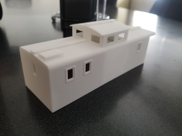
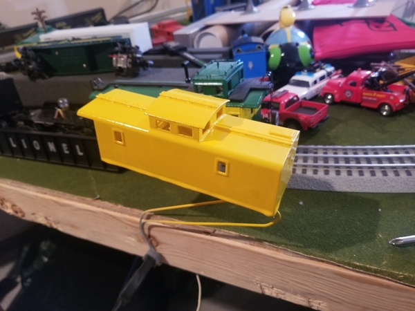
This is the White Pass and Yukon Route number 907 Rotary Caboose. This caboose was specifically designed to work on the rotary snow plow train. It even had flangers under the rear platform when backing. I finally got around to printing it out.

From 3d computer model:mceclip0

To a rough print:20200306_142738

Add a Lionel postwar caboose frame:20200307_161055

Add a yellow coat:

20200308_150929

Add green paint and decals:

20200310_232927

Add a vinyl sticker:

20200311_000555

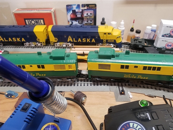
And tow it around the track with a 3d printed engine:

20200326_213912

Attachments

Images (8)
  • 907_whse_grye
  • 20200306_142738
  • mceclip0
  • 20200307_161055
  • 20200308_150929
  • 20200310_232927
  • 20200311_000555
  • 20200326_213912

More work on my shovelnose diesels continues. I have now wired up a powered dummy to help with conductivity issues. They are now connected by a tether that supplies power from the dummy to the motor and supplies backup lights to the dummy.

20210311_201008

20210220_094801

After completing the wiring I wanted to better secure the shells to the frames. These frames are simple Postwar alco frames. I drilled through the frame and then drilled a hole in this piece of styrene I added. I am using something called heat set inserts. These are normally used in electronic repair and custom builds.

20210218_195615

Attachments

Images (3)
  • 20210311_201008
  • 20210220_094801
  • 20210218_195615
Videos (1)
20210218_195625

My EC-4 is getting completed. The view above shows a very early version that has morphed into 3  roof sections, all three sections are equal lengths.  This saved about 3-1/2 hours of print time from an earlier earlier version! It did require changing the laser cut base holes for adjusted and relocated supports. The newest version looks more like the EC-4 with side panels and detailed lower piping of elements on the actual EC-4.

Also, I made the all eight (8) light housings separate-able to be inserted and attached after being wired.  I posted this before.EC-4 v19 assembled

the view above doesn't show the three equal roof sections or the sliding side panels.

Attachments

Images (1)
  • EC-4 v19 assembled
@AlanRail posted:

My EC-4 is getting completed. The view above shows a very early version that has morphed into 3  roof sections, all three sections are equal lengths.  This saved about 3-1/2 hours of print time from an earlier earlier version! It did require changing the laser cut base holes for adjusted and relocated supports. The newest version looks more like the EC-4 with side panels and detailed lower piping of elements on the actual EC-4.

Also, I made the all eight (8) light housings separate-able to be inserted and attached after being wired.  I posted this before.the view above doesn't show the three equal roof sections or the sliding side panels.

This is a great model. Will the vacuum fit entirely inside? Or will it stick out of the top?

Even though this is not a motorized-car ( like the original that has transmission issues so it is pushed) the electrical wiring to all eights sets of LED lights is a lot as are the various parts (there are over three(3) dozen Laser cut and 3D laser printed parts).

I  dont think I will ever try to build a 3D resin car again. I have designed and redesign AND PRINTED close to two dozen versions before the final one that is sitting on my desk waiting to be completed.

Add Reply

Post

OGR Publishing, Inc., 1310 Eastside Centre Ct, Suite 6, Mountain Home, AR 72653
800-980-OGRR (6477)
www.ogaugerr.com

×
×
×
×
Link copied to your clipboard.
×
×