I had a problem...  I had this Aux Water Tender and the previous owner had obviously abused it, almost every one of the stanchions were broken!  I made a glue attempt several times, but either the material or the size made it difficult to impossible to get something that would stand even the gentlest of handling.  Of course, these are unobtainable from Lionel, why stock the part that's most likely to break?

A conversation about the possibility of  3D printing the stanchions with @AlanRail yielded a perfect answer!  He generously 3D printed an entire set of stanchions to the exact specifications needed to repair the tender.  The only extra step was painting them black from the gray plastic color, that was really easy!

Disassembling the railings was a big interesting, these were obviously not meant for maintenance.  However, it was accomplished, and now my tender has returned to it's former glory!

Lionel 6-38006 Grayhound Auxillary Water Tender

After seeing the level of detail possible with a decent 3D printer, I can imagine a parts revolution for obsolete parts, the stanchions have amazing detail for something so tiny!

Let's hear a round of applause for Alan, a huge THANK YOU!

dogs-dog

Attachments

Images (3)
  • Lionel 6-38006 Grayhound Auxillary Water Tender
  • mceclip0
  • dogs-dog
Original Post

Replies sorted oldest to newest

@AlanRail posted:

thanks all.

I am having issues with my FormLabs 3 printer's connectivity.  Formlabs people are really responsive.

They are sending me a replacement new printer, the latest one, the FormLabs 3+

This is an upgrade to my FL3. Prints on the "plus" version are sharper than the 3.

FormLabs is located near MIT in the USA.

Wow, that's good customer service!  I see why it makes good prints! Starting at$3,750.00

Clearly, these are a cut about the $500 3D printers!  From the reviews I read, the FormLabs stuff is the top of the heap!

Great work by @AlanRail. John- I'm sure you are happy to have the tender restored to it's original glory. I hope these get added to the 3D Project Catalog.

3D printing has revolutionized many industries. The applications in modeling are endless. I saw story on-line the other day about a group of engineers are architects that are 3D printing a 2 story house. Pretty cool!

Bob

@Ron045 posted:

I'm confused on how the replication process starts.  Does the machine scan the part you want to replicate or does a human need to draw it in CAD?

I suspect most often, as it was in this case, a human indeed drew it in CAD.  If I were proficient in using 3D CAD, I'd probably consider a 3D printer.  IMO, that's by far the biggest barrier to getting full use from a 3D printer.  Of course Alan also has a high quality resin printer, that probably helps with the actual printing and the look.

Scanning is good for complex models like dinosaurs with multiple surfaces. Good scanners are expensive.

Our models are more rectilinear and/or circular. So not nearly as hard to model.

Most solid modeling programs allow you to take a 2D drawing and extrude it into 3D. I usually import one or more photos into my program and use it as a basis for the model.

Last edited by AlanRail

OK  I was asked to make some F7 stair steps. These steps have 2 surface tread designs.

so first I measured the step using a digital caliper. The step comprises three basic pieces: a rectangular box and two cylinders.

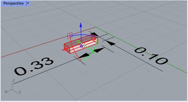
In the 3D program (Rhino 7) I made a rectangle sized with the length 0.33" and width .10" of the step.

rhino rect

the dimensions are just for illustrative purposes. Next, I extrude the 2D rectangle intorhino rect extru

3D using the .06 "thickness I measured. the xyz manipulator is shown, so clicking on the green Z direction dot allows

extrusion in the z direction. Since Rhino is a surface modeler, I now have 4 surfaces created.  So to make it a solid, I cap the sides with a top and bottom surface.

rhino rect extru cap

Now i have a solid rectangle for the step; next I  need two pins to insert into the F7 body. The pins are created with two circles equally spaced along the long side. doing the same extrusion with the circle, i have two pins.

rhino step

I did skip a few steps in that I rounded the ends of the pins and added a small cylinder on the end of the pins next to the step to act as an insertion stop.

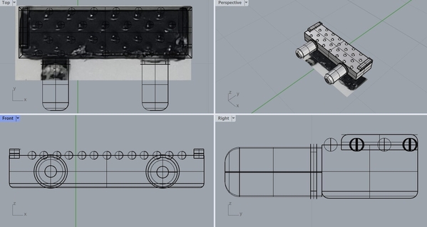
Now I drag the actual step photo into Rhino. I carefully scale the photo to match the size of the step. Note the tread designs.

rhino step photo

I then match the photo's tread designs.  The tread designs consist of 4 rows of submerged spheres and two end step ledges. Easy to make and easy to evenly place. See below.

rhino step tread design

And then make a .stl model to print.

F7 stair steps x 10printed F7 stair step [2)


That is how I use a photo to make a 3D model. 

Attachments

Images (9)
  • rhino rect
  • rhino rect extru
  • rhino rect extru cap
  • rhino step
  • rhino step photo
  • rhino step tread design
  • f7 stair step printed
  • printed F7 stair step (2)
  • F7 stair steps x 10
@AlanRail posted:

Most solid modeling programs allow you to take a 2D drawing and extrude it into 3D. I usually import one or more photos into my program and use it as a basis for the model.

This is most commonly described as Converting a 'Raster' Image to 'Vector' Graphics.  It's been done for a very long time.  When a designer wants to scale an image and does not want it to become pixelated it's converted to a vector.   Drop the vector into CAD, grab your calipers, add the 3rd dimension... and, you are off to the races.

Last edited by Dennis-LaRock

I got a Legacy Y6b with some cosmetic challenges last York. It was missing this mystery part (muffler for the separator?).  A pal sent me a photo of it and then I snapped one of my own of the Y6b sitting in the TCA museum. This part was done on my resin printer. One thing I like about the resin printer for detail parts is that you can core a part all the way through very nicley:

846280D3-7CC3-4CE3-960C-A9C3FF31B8A4DA62C6F0-D02B-4DAB-A1EF-7DB76E6FCE9615902B6B-13E1-4D3A-A9A8-7F27E314DC0B

Attachments

Images (3)
  • 846280D3-7CC3-4CE3-960C-A9C3FF31B8A4
  • DA62C6F0-D02B-4DAB-A1EF-7DB76E6FCE96
  • 15902B6B-13E1-4D3A-A9A8-7F27E314DC0B
@AlanRail posted:

OK  I was asked to make some F7 stair steps. These steps have 2 surface tread designs.

so first I measured the step using a digital caliper. The step comprises three basic pieces: a rectangular box and two cylinders.

In the 3D program (Rhino 7) I made a rectangle sized with the length 0.33" and width .10" of the step.


the dimensions are just for illustrative purposes. Next, I extrude the 2D rectangle into

3D using the .06 "thickness I measured. the xyz manipulator is shown, so clicking on the green Z direction dot allows

extrusion in the z direction. Since Rhino is a surface modeler, I now have 4 surfaces created.  So to make it a solid, I cap the sides with a top and bottom surface.


Now i have a solid rectangle for the step; next I  need two pins to insert into the F7 body. The pins are created with two circles equally spaced along the long side. doing the same extrusion with the circle, i have two pins.


I did skip a few steps in that I rounded the ends of the pins and added a small cylinder on the end of the pins next to the step to act as an insertion stop.

Now I drag the actual step photo into Rhino. I carefully scale the photo to match the size of the step. Note the tread designs.


I then match the photo's tread designs.  The tread designs consist of 4 rows of submerged spheres and two end step ledges. Easy to make and easy to evenly place. See below.


And then make a .stl model to print.


That is how I use a photo to make a 3D model.

Is that extra plastic re-usable or is it waste? Why is there so much compared to your step?

Last edited by Ron045

Add Reply

Post

OGR Publishing, Inc., 1310 Eastside Centre Ct, Suite 6, Mountain Home, AR 72653
800-980-OGRR (6477)
www.ogaugerr.com

×
×
×
×
Link copied to your clipboard.
×
×