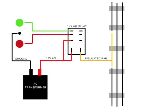
If using a 12v AC ice-cube style relay, can a capacitor be added to reduce, or eliminate, the chatter when entering or exiting the block? 

The scenario would be an AC transformer providing 12-14v to both the signal and relay.

If so, where, on this diagram, would the capacitor be added?

What size capacitor to use?

And what about the polarity of the capacitor?

Thanks,

Mike

Screen Shot 2016-02-18 at 9.16.46 PM

Attachments

Images (1)
  • Screen Shot 2016-02-18 at 9.16.46 PM
Original Post

Replies sorted oldest to newest

Actually John, it might chatter, but not because of the coil, but because of intermittent contact of the wheels on the insulated rail.

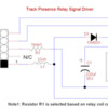
This little gizmo was designed by an electrical engineer I once knew. We used 24VDC relays. The DC ground was combined with the AC ground on the track. The 24VDC went to two of the terminals on the circuit, the third went to the insulated rail trigger. The trim pot adjusted the discharge rate of the cap, and voila, poor man's timer. Even at the lowest setting, it stopped all chattering. Longer settings  were useful for other things.

delay circuit

Attachments

Images (1)
  • delay circuit

RTR12,

I think most folks using DC relays are powering them from a source regulated in some manner to whatever voltage is needed for the relays, 5 or 12 VDC usually.  This positive side, VCC, or whatever you'd like to call it is connected to one side of the relay coils.  the negative, ground, or what-have-you from the power supply is then connected to the U post/ out side rail.  The other side of the relay coils are connected to the insulated track rails such that the axels connect the ground side of the relays, not the "+" side.  Track voltage then has no effect on the operation of the relays.  

As for different ways to provide this 5 or 12 VDC power, you could use an HO 'transformer' if you got one laying around, an old wall wart from some device you don't use, or perhaps the most common one I've seen lately are the cheap, buck-converters from china available on the auction site.  


On the original question of stopping the chatter, I can not think of a solution that would be anywhere near as cost effective AND simple as replacing the AC relays with DC ones... unless you already own a large number of the AC relays, they have very high contact ratings, and you need them to control very high voltage or current (ex. over 10 amp/250VAC) In that case I would use the lower rated DC relay to power the coil on the AC relay.  

As another note you can typically power AC coil  relays off DC.  You need a lower voltage, and I'm not sure how to figure that voltage out.  I would guess something in the range of 70% of the AC coil voltage.  So, if you already own many of these relays you could also try using them just as GRJ's circuit shows, but powered off around 8.5VDC.  Though 70% seems to work by the math for RMS values, it may not be right... I would probably use it as a starting point, but end up at whatever the lowest voltage that can reliably throw the contacts is.  (under load, as it may take more power with high current running through the contacts.)

JGL

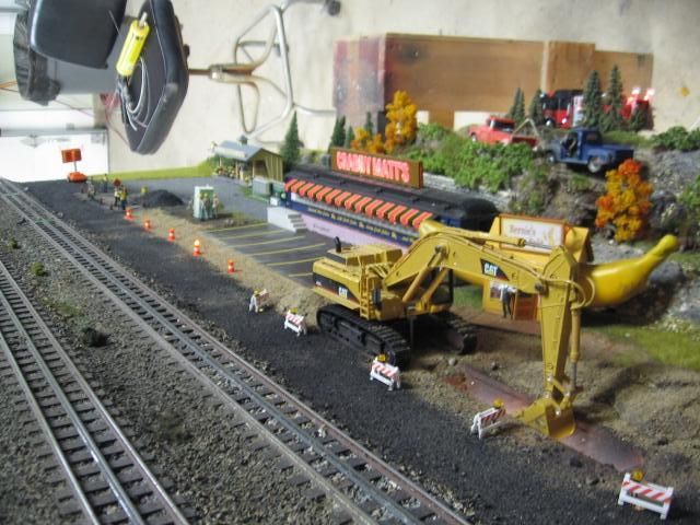
Another approach to the relay voltage related to 18 volts AC, (train), is to supply a 24 volt relay and power it at 20 to 22 volts ( a max) available from (train transformers).   The animated back hoe on this module has a 120 volt motor. We (Fort Pitts Highrailers) didn't want to apply 120 volts to a push button to operate the backhoe. The push button has public access.  So we used a 24 volt relay, 120 volt contacts, and used track voltage, via the push button to activate.  The 24 volt relay works O.K. at 20 volts, any lower, and it began to chatter.    


Last edited by Mike CT

Does it perform the same way if you put a different car at the end of the train? (probably not).

The real answer is that during the travel of the entire train, there are always more than one axle making contact. Each axle will make contact and lose contact, many times, but since there are more than one axle, they compensate. At the end of the train, there comes a time when there is just one final axle, and due to the intermittent contact areas of one axle (rail to wheel to axle to wheel to rail) there will be chatter, or a blip.

Switch your thinking to using DC. DC is the only sane and reliable way to do electrical controls that involve timing, matrices, and wired logic using diodes.

JohnGaltLine posted:

RTR12,

I think most folks using DC relays are powering them from a source regulated in some manner to whatever voltage is needed for the relays, 5 or 12 VDC usually.  This positive side, VCC, or whatever you'd like to call it is connected to one side of the relay coils.  the negative, ground, or what-have-you from the power supply is then connected to the U post/ out side rail.  The other side of the relay coils are connected to the insulated track rails such that the axels connect the ground side of the relays, not the "+" side.  Track voltage then has no effect on the operation of the relays.  

As for different ways to provide this 5 or 12 VDC power, you could use an HO 'transformer' if you got one laying around, an old wall wart from some device you don't use, or perhaps the most common one I've seen lately are the cheap, buck-converters from china available

On the schematic above that GRJ posted, the relay marked as 12V coil was looks like it's being powered from the terminal marked 'center track' using a choke (for DCS) and diode and an isolated rail for common. I was just wondering if the one diode was enough to reduce command voltage to something useable by the 12V relay? The terminal marked 'Center Track' was what got me wondering?

I have AD/DC converters and even some DC power supplies, but I am not certain how much voltage a bridge rectifier or diode drop the voltage...like the half wave/full wave, RMS and all that stuff? That is what I was wondering about.

John H posted:

This is all good information, but doesn't really explain why the chatter only occurs at the last car.

Arthur just summed it up pretty well as to why chatter happens, or is more likely right as the train is leaving the isolated block.  

Running on nothing but whatever sense I can make of it, and pulling things out of... a hat?... I suspect that there is going to be less chatter at the start as an engine enters the section as locomotives generally have much more conductive leading trucks and a whole lot more weight applying pressure on those wheels, leading them to make better contact with the rails.  Better contact makes for less, or no chatter.  

I suspect that if the same train were run into the section backwards the pattern of the chatter would reverse as well.  

JGL

rtr12 posted:

On the schematic above that GRJ posted, the relay marked as 12V coil was looks like it's being powered from the terminal marked 'center track' using a choke (for DCS) and diode and an isolated rail for common. I was just wondering if the one diode was enough to reduce command voltage to something useable by the 12V relay? The terminal marked 'Center Track' was what got me wondering?

Look closer.   The resistor is also in the coil circuit, that's how I adjust the coil voltage.  This was created with command operation in mind, and for simplicity I run them from track power, the relays typically are 20-30ma coil current.  The relay drops the voltage to the proper level and also limits the inrush current charging the capacitor to avoid arcing at the wheels when the capacitor is first charging.

Last edited by gunrunnerjohn
gunrunnerjohn posted:

Note the resistor in series with the circuit for the relay.  I adjust that relay to get around 11-13 volts DC on the relay.  The value is dependent on where I salvage the relays from , the coil current varies for different sources.  That circuit is "tried and true", and once I install them, I have never had to revisit them.

Hmmm...Resistor indeed...Who put that there? I must have looked at that thing at least 5 or 6 times and didn't even see it until I read your post.   And this is after having my eyes fixed last summer too... just think what it was like before that!

Thanks, that's much better! I should be up watching TV instead of being on here...

JGL,

I have it now, GRJ straightened me out. Thanks.

Last edited by rtr12
rtr12 posted:

On the schematic above that GRJ posted, the relay marked as 12V coil was looks like it's being powered from the terminal marked 'center track' using a choke (for DCS) and diode and an isolated rail for common. I was just wondering if the one diode was enough to reduce command voltage to something useable by the 12V relay? The terminal marked 'Center Track' was what got me wondering?

I have AD/DC converters and even some DC power supplies, but I am not certain how much voltage a bridge rectifier or diode drop the voltage...like the half wave/full wave, RMS and all that stuff? That is what I was wondering about.

Ok...  this has a number of answers, depending what parts you're using.  

1. Using only a single diode will effectively cut AC RMS voltage in half as it kills the half of the AC wave negative to its polarity.  However the voltage will turn on and off at 60 cycles, it's still AC.  For something like a light bulb this will work out ok, but might cause a chatter in a relay.  I'm not really sure on that.  It is pretty much useless for any sort of solid state device.  

2.  A single diode with a capacitor across the ground and diode's 'output'.  With the cap added, it stores energy so that as long as the load is not enough to drain the Cap before the next cycle it will hold the voltage at a constant level.  This voltage is a bit hard to figure the math on, and I couldn't locate a formula on it as most folks tend to use a bridge rectifier and/or use the single diode and cap(half wave rectifier).  It works similar to a bridge rectifier (see below), but because the input voltage peaks half as often and the capacitor must hold the voltage over the 'negitive' half of the wave, the effective voltage is slightly lower than the 1.4141 multiplier used on a bridge rectifier.  

3.  Diode bridge: using 4 diodes set up in the format of a bridge allows the current to pass through from both sides of the AC wave, allowing the full energy of the AC to move to the +/- leads.  It is still an oscillating wave, but rather than moving in the familiar sine pattern it is converted to a series of positive bumps, each starting at the end of the last.  In the end this behaves similar to using a single diode, and I can't recall ever seeing a non rectified diode bridge.  

4.  The bridge rectifier:   by combining the bridge with a capacitor to hold the energy of the oscillating current the bridge rectifier supplies the full energy of the incoming AC current, again, so long as the cap is large enough to power the load.  When you convert AC to DC the DC voltage is approximately 1.4141 times higher than the AC voltage.  This is because of the way AC voltage is measured for it's ability to power things.  You've probably seen the term RMS on meters and such.  This is Root Mean Square and what it means is that you take a number of measurements of the voltage throughout the arc of the rising and falling sine wave, the more measurements the better.  Each value is squared (multiplied by it's self), then the total of all reading on that wave are added together.  The value is averaged by dividing by the number of readings taken (mean).  The square root of that average value is then taken as the value, or ac voltage, and fairly effectively shows the useful energy in the AC power.  The capacitor in the bridge rectifier, however, holds the peak voltage of the wave, which works out to being about 1.4141 times higher than the RMS voltage of a 60 cycle sine wave.  

So with a full wave bridge rectifier (4 diodes and a capacitor) the DC voltage is substantially higher than the AC input voltage.  this is why you see volks suggesting using at least 35V rated caps and such in the circuits even though track power is 18VAC( 35v is often the first standard value higher than 25v).  That 18 VAC when rectified produces over 24VDC.  

As one last bit to mess with the math, a typical silicon diode will drop about 0.6 volts off the current passing through it.  this is a good way to drop voltage as opposed to using a resistor because diodes are a whole lot less expensive for the current they can handle.  for example, to cut the brightness of a little 5 watt light bulb in half you would also need a 5 watt resistor.  not the cheapest or easiest thing to come by.  On the other hand a string of 1n4001 diodes cost around a penny each, and can handle the same current as an 18 watt resistor at 18V.   

I think I just came up with an idea for my first video on electronics... 

JGL

JohnGaltLine posted:

Ok...  this has a number of answers, depending what parts you're using.  

1. Using only a single diode will effectively cut AC RMS voltage in half as it kills the half of the AC wave negative to its polarity.  


Well, as long as we are going on and on.....

I see the above statement here all the time and, while intuitively satisfying, it is incorrect. The RMS voltage value of a half sine wave is 70.7% of the full wave value, not 50%! To think about it correctly, picture that a half-wave rectifier delivers power only half the time. But, P=V**/R, so getting half the power equates to 70.7% voltage. Or, I can do the math offline if you want. 

Note that this is about RMS values, if you are worried about peak-to-peak or average it is a different story.

Practically, this means that unfiltered 1/2 wave rectified 18V gives about 12.7 rms volts, plenty close enough to use with automotive 12V lamps and all that. It will also not overheat a 12VDC relay. and will pull it in just fine. It will probably buzz, however, in many cases the presence of the flyback diode is more than enough to solve that.


JGL,

Thanks for the added details. I can never seem to get this stuff straight and remember it, even though it has been explained before. I think I'll print this one out an put it on the bench this time for reference.

I was thinking about the diode and looking at the power to the relay coil and seeing right past GRJ's resistor, that didn't even register until I read his additional post above. This morning I see there is even a note about it at the bottom of the schematic...  I had completely missed all that before, it just went right by. Must have been the phase of the moon?

PLCPROF,

Thanks for the added explanation and clarification. This is also headed for the printer.

Last edited by rtr12

FWIW, in many cases, I don't use a diode bridge in a power supply for one simple reason.  With a diode bridge supplying your circuit, your DC ground is no longer your frame ground.  This presents a real problem for some environments, specifically the standard TMCC configuration.  Many of the signals for the R2LC/R4LC are frame ground referenced.  In order to be compatible with that environment, any circuit interfacing to them has to take that into consideration.  That's why my Super-Chuffer uses a simple diode to rectify the track voltage and simply uses a larger capacitor for smoothing.  OTOH, my lighting regulator module uses a full-wave bridge as I didn't need a common DC to frame ground reference for lighting.


Just an aside explaining why you'd want to use the "inefficient" half-wave rectification at times.

PLCPROF, by the math, you are correct, half a sine wave will produce 70% RMS value of the full wave.  I don't think you will actually see 70% if you place a meter across your load, however.  Guess I need to check it out when I have time.  Of course this is only if using RMS for an AC reading.  The DC voltage will be quite a bit lower unless filtered with a capacitor.  

GRJ, yep, there are reasons to use a half wave rectifier besides just cost.  

In related information I've been digging at today, Lionel seems really big on using half wave, unfiltered, but rectified, AC to power their motors in legacy engines.  Not a bad way to put about 12 volts to a 12VDC can motor, I suppose, even if it is less efficient than using PWM DC.  

JGL


Getting back to the original premise of this thread, with all the opto-isolated Arduino compatible relay boards available, has anyone used one of these with a 5V supply to make a control rail? Seems like the anti-chatter capacitor could be much smaller if it only needs to support the load of an opto-isolator. The relays on these boards are less than a dollar apiece!

Add Reply

Post

OGR Publishing, Inc., 1310 Eastside Centre Ct, Suite 6, Mountain Home, AR 72653
800-980-OGRR (6477)
www.ogaugerr.com

×
×
×
×
Link copied to your clipboard.
×
×