Hi,

I have an MTH 30 -79452 log dumper. I am not sure how to bench test it for operation. The littles are blaming one another for dropping it. Trying to sort out if it's the car or the FasTrack activation track.

I have 14v AC track power on that line. I am getting ~ 2.4 volts on the activation rails which is jumpered for track power supply when I push the unload button.

Do I ground the chassis and power to both shoes or ground to one shoe  and power to the other to test the car operation?

I don't see anything physically wrong with the car, unless the shock jammed the arm to push the car body up.

Any help would be appreciated.


Original Post

Replies sorted oldest to newest

You should get "full" 14V AC between the left and right activation rails when pressing UNLOAD.

Since the UNLOAD lever is momentary, it is just to activate the function and track power must also be applied to the wheels and center rail roller(s) for the operation to run to completion.

So if testing on the bench with operating car on its side, upside down, whatever, you need to jumper track power to the wheel and center-rail roller.  Then momentarily jumper track power to the 2 sliding shoes to simulate throwing the UNLOAD control lever. 

stan2004 posted:

You should get "full" 14V AC between the left and right activation rails when pressing UNLOAD.

Since the UNLOAD lever is momentary, it is just to activate the function and track power must also be applied to the wheels and center rail roller(s) for the operation to run to completion.

So if testing on the bench with operating car on its side, upside down, whatever, you need to jumper track power to the wheel and center-rail roller.  Then momentarily jumper track power to the 2 sliding shoes to simulate throwing the UNLOAD control lever. 

The MTH car doesn't have a center roller - just a spring mounted slide contact , one on each side. It is a motor that slowly lifts the cats and returns it down.

I checked my track, it's ok on the pass through voltage when the button is depressed.

I checked the slider pick-ups to power converter board - the continuity is good, but I can't get on the little solder tabs on the power board to confirm AC in an DC out. I'll try later.

I don't see how a fall would damage that. It was mounted to a post with the heat sink of a device on the bottom. I really wanted to see AC in and DC out or not. I can imagine the motor gear package getting jammed from a fall. It has a cam on it.

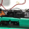
So, a little more testing tomorrow. I'll put photo up of the guts.

Thanks, Stan.


Last edited by Moonman

My mistake - I was thinking of a different MTH operating car circuit that automatically stops at the end of the cycle.  In this case it appears the motor runs as long as the UNLOAD lever is thrown and immediately stops when released no matter where it is in the cycle.

So that board is just an AC-to-DC converter board with a regulated DC output so that the motor runs at fixed speed irrespective of track voltage.  Seems to me you just need to see confirm 14V AC at the input and fixed DC at the output.  I suspect the fixed DC output voltage is 8V or 9V DC determined by the 3-terminal IC voltage regulator chip which is bent such that we can't see the markings which would of course indicate the voltage (e.g., 7808 = 8V, 7809 = 9V, etc.).

If you get 14V AC in, but no DC voltage out, I suppose there's a chance of a component failure though hard to believe simply dropping the car would do this.

yes, I called it the motor package, because, one holds the button, it lifts the car to full tilt, pauses with a shaking motion and returns to down position. So, there's another board in the motor package. it's a nice, slow dump operation.

perhaps the grandkids sparked it. I am going to get some more stuff out. I was trying to test it on the track, hold the button, hold the board and get some readings. Time to head to bench. I'll see if I can get a number off of that round piece.


I realize you need 6 hands to make the measurement but just want to be sure we're on the same page.  I'd make the following 3 voltage measurements with the lever held in the UNLOAD position (or with wire clips going from 14V AC to the two sliders).

Measure 14V AC going into the board.  Measure the TBD DC output voltage leaving the board.  And while at it, the unregulated DC voltage which should be about 18V DC.  Hard to tell from photo but you might not be able to easily bend up the regulator chip to read its markings.  I believe you will measure 8V or 9V DC on the motor voltage output.

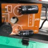
Log_Dump_Car_Board_Side_B

Attachments

Images (1)
  • Log_Dump_Car_Board_Side_B

Stan,

I have the car on the activator track , button held down.

I get 14 vac in, I get .35 DC volts unregulated, not 18  across the round thingy leg and motor - lead and I have nothing to the motor + and -.

Can it be fixed or should I order a new board?

Would I have to disconnect the motor leads to test with DC from a 9 volt battery?

Thanks, again.

Yes, disconnect 1 of the motor leads to test with 9V battery...though may be easier to disconnect both wires for easier connection to  battery.

The "round-thingy" marked RB152 is a bridge rectifier.  If you're only getting 0.35V unregulated DC, it does seem to point the finger at the RB152.   But just to be sure, double check with the best magnifier you have available at all the connections and solder joints around the RB152...and the body/case of the RB152.  I'm looking for any hairline cracks or whatever possibly from a sharp impact when dropped.

If the motor runs with 9V battery, this is probably the "best" news.  I figure the replacement motor gearbox mechanism would be, say $20-25, replacement circuit board would be $5-10.  The round-thingy is one of those 10 for $1 components on eBay...a bit more from US but widely available (the kind of part even your local Radio Shack might carry if they're still around).  Yes, it would involve cutting/removing the 4 legs and soldering the new part in.


Last edited by stan2004

I did have to break out my third hand jig with a lighted magnifier to hold the board. I'll eyeball the rectifier for some physical damage.

The flux or coating that is on the factory board was a pain, so I went from the + leg to the - motor wire. The solder dot was clean.

Ok, I'll unsolder the motor package wires and test it with a battery.

The grandkids are five and six and usually good around the trains when I don't have eyes on them. I suppose they got me. Their story was a drop, but Noah knows how to power up the layout. He may have sparked (shorted it) the car trying to put it on the track. It's a little heavy as it is all cast. It's freezing here, so I need some indoor activities.

Yep.  Another one of those you'll pay more for shipping than the part itself!

Perhaps obvious, but orientation/polarity is important when you install the part.  The case is marked +, -, ~, ~.  As shown in the Radio Shack equivalent part it will come with the 4 legs in a square whilst you will have to bend the legs in a single-row to fit the board holes.

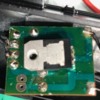
Untitled

Attachments

Images (1)
  • Untitled

Yep, I paid 27¢ each for 5 and $4 + shipping. Still cheaper than a new board , if I could get one.

The specs on RB152 show Vf forward voltage as 1 volt. Is that all that it will pass through to the circuit? The 9 volt battery on the motor did seem to run it too fast?

Thanks for the heads up on the markings/ legs. I have worked with other bridge rectifier package styles.

Is there anyway that I can check the rest of the circuit? Can I jumper DC in to + /- legs and check for voltage at the motor outputs?


Attachments

Images (1)
  • RB152
Last edited by Moonman

There are 4 diodes in a bridge rectifier.  A diode passes current in one polarity (forward mode) and blocks the current in the other polarity (reverse mode).   Vf refers to the diode voltage that is dropped and effectively lost when passing current.  When a bridge is properly operating, 2 of the 4 diodes are in the forward mode and the other 2 are in the reverse mode.  As the polarity of the incoming AC alternates, so do the pairs of diodes (each pair alternates forward-reverse-forward-reverse, etc.).  So you actually get 2 x Vf drop in voltage since 2 diodes are in forward at any given time.  If starting from 14V, you have plenty of voltage and can tolerate this 2 x Vf drop from the bridge.

The purpose of the IC regulator chip (folded with its markings facing downward) is to provide a fixed DC voltage to the motor.  Based on your comment that a 9V battery drives the motor too fast, I suspect that regulator might be 6V or 8V (which are common values for such a regulator chip).  I don't think think its worth the risk of breaking a leg on that device to bend it up.

You can attach your 9V battery and the motor should operate.  It is absolutely critical that you apply the battery in the correct polarity (+ to +, - to -).  In the case of directly driving the DC motor box with a 9V battery, if you applied the battery backwards the motor likely have run just fine but just in reverse.  But if you apply the battery backwards at the RB152, you might explode a capacitor.  Anyway, the motor will run slower because, like a diode, the regulator IC too has a voltage drop...probably about 1-2V.  So your 9V input might become, say 7-8V at the motor terminals...but no more than whatever the unknown voltage rating of the regulator IC chip.  You can perform this with the RB152 installed or not...in case you already removed it in preparation.

Separately, does you meter have a so-called "Diode Test" setting?  Icon something like that shown below.

diode test


Attachments

Images (1)
  • diode test
Last edited by stan2004

yes, I do have the diode test (an older fluke 87 III)

I tested the forward bias on the diode + & - and got a 0L reading with the line on the bottom full, like a short in a continuity test. it's still in circuit or on the board, but the probes were up on the legs.


So, if I ensure polarity is correct and clip the battery to the + and - diode legs that would be the safe way to check the rest of board.

Last edited by Moonman

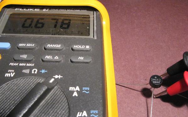
bridge diode test

On a Fluke 87, the "OL" reading in diode-test mode indicates an open-circuit or diode in reverse-mode.  If you have a minute or two, what you want to do is make a series of 8 measurements on the un-powered bridge.  This can be done with it soldered in the board.  Note that none of these measure from + to -

red to ~1, blk to + (this case is shown in photo above).  then reverse red and blk and re-measure.

red to ~2, blk to +.  then reverse

red to ~1, blk to -.  then reverse

red to ~2, blk to -.  then reverse

there is no ~1 and ~2 per se...just two ~ so I'm just arbitrary calling one ~1 and the other ~2.

A working bridge will show about 0.7V in one direction and OL in the other direction for each diode.  I'm pretty sure you won't get this!


And, yes, after you double and triple check for polarity, you can hook the 9V battery to the + and - legs of the bridge.  The motor should turn a bit slower than when the 9V was directly applied to the motor.  If you have enough hands, measure the motor voltage as it spins.


Attachments

Images (1)
  • bridge diode test
stan2004 posted:

bridge diode test

On a Fluke 87, the "OL" reading in diode-test mode indicates an open-circuit or diode in reverse-mode.  If you have a minute or two, what you want to do is make a series of 8 measurements on the un-powered bridge.  This can be done with it soldered in the board.  Note that none of these measure from + to -

red to ~1, blk to + (this case is shown in photo above).  then reverse red and blk and re-measure. .583   .578

red to ~2, blk to +.  then reverse  .0L     .0L

red to ~1, blk to -.  then reverse   .0L    .568

red to ~2, blk to -.  then reverse    .0L    .0L

there is no ~1 and ~2 per se...just two ~ so I'm just arbitrary calling one ~1 and the other ~2.

They actually marked the board + and minus for ~ (AC) , so, I oriented that slide pickup on the hot activation rails, I know, over thinking

A working bridge will show about 0.7V in one direction and OL in the other direction for each diode.  I'm pretty sure you won't get this!

I certainly did not    


And, yes, after you double and triple check for polarity, you can hook the 9V battery to the + and - legs of the bridge.  The motor should turn a bit slower than when the 9V was directly applied to the motor.  If you have enough hands, measure the motor voltage as it spins.

yes, I would hope it turns slower as the dump movement, top and return is slow

I certainly appreciate your patience and educational efforts. It will certainly help with future train repairs.

The bridges are on a slow ride from Texas, perhaps I should have ordered a board from MTH. Oh well, I will repair it next year.

I'll post the results of the powered board test and take a voltage reading of the output to the motor.


Given the diode-test readings you made earlier, + and - legs of the bridge are not shorted.  This is a very strange result.

Put your meter in Ohms mode, and measure red to bridge +, and blk to bridge -.  If there is indeed a short-circuit this would of course measure something close to 0 Ohms.  The normal reading would be a very high number (thousands-millions of Ohms).

I suppose since you have to remove the bridge anyway, you can just go ahead and clip the 4 legs of the bridge to remove it so no soldering iron required (make note of orientation of course). 


Add Reply

Post

OGR Publishing, Inc., 1310 Eastside Centre Ct, Suite 6, Mountain Home, AR 72653
800-980-OGRR (6477)
www.ogaugerr.com

×
×
×
×
Link copied to your clipboard.
×
×