
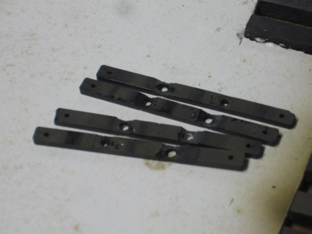
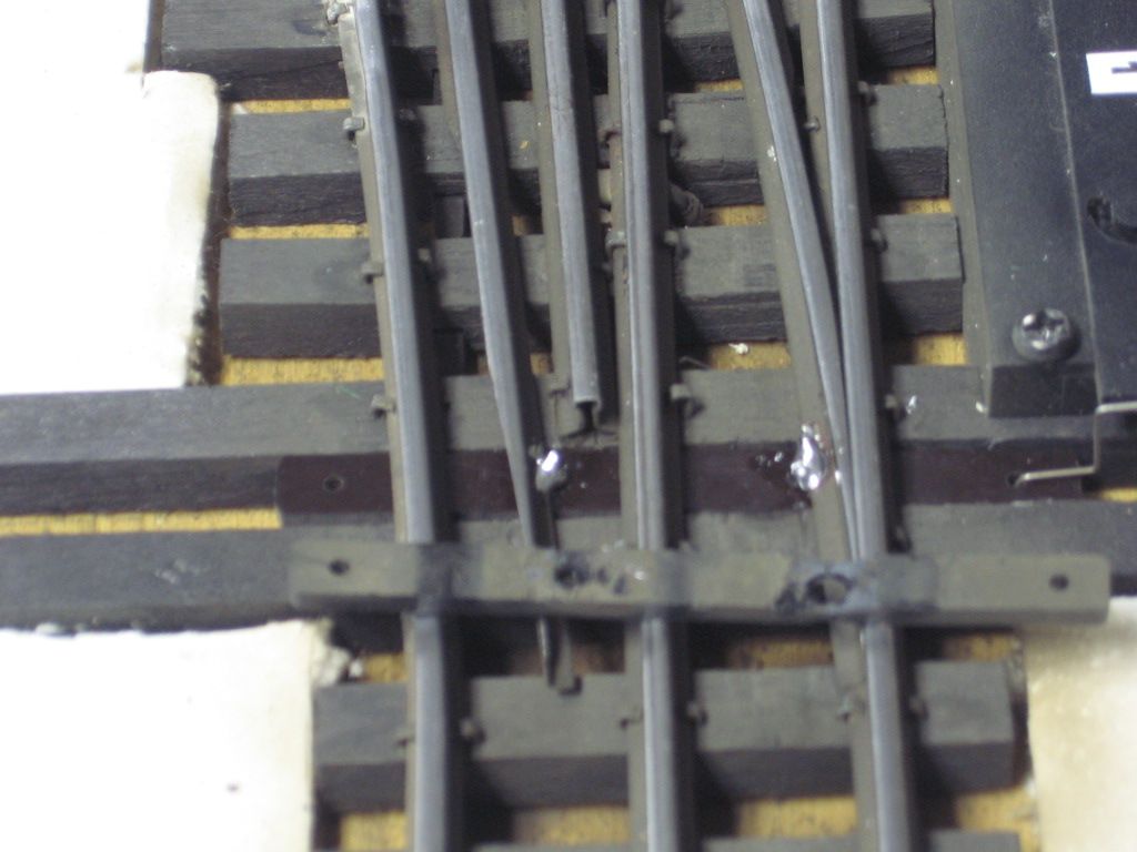
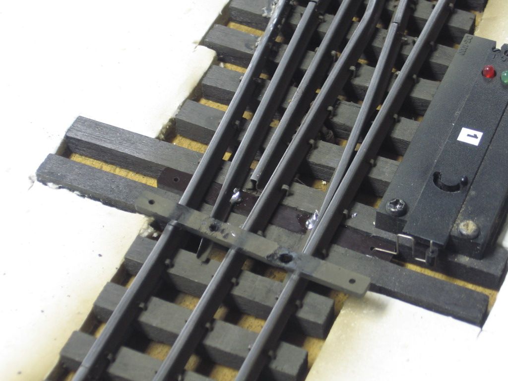
The drawbar broke at the rivet where the point is soldered to the rivet on the drawbar. While Ross has fixed broken switches for me in the past, I want to see if anyone has replaced the drawbar themselves, with the switch embedded in the track work on the layout. I speculate that if I heat the top of the points with the solder gun where the point is soldered to the rivet I can remove the broken one - and then slide a new drawbar in and line up the rivets to the points and add a bead of solder. Has anyone done this? If its not possible to due with the switch installed then I'll have to remove the switch, in which case I'd just send it back for them to fix correctly. If I can avoid having to remove the switch and do the repair in-situ then I'd give it a try, once I get a new drawbar.

Original Post

Replies sorted oldest to newest

Paul;

I've done several of these without removing the switch from the layout. There are a few things of which to be aware:

  • First, prep the new drawbar by inserting the the new rivets.
  • To get the new drawbar in with the rivets inserted into the drawbar, it's necessary to remove the strip of material that runs under one of the outside rails. Otherwise, the rivet won't pass underneath the rail.
  • Some Ross switches have the moving rails made out of aluminum. These rails have holes through which the rivets pass and the rivets are secured by putting solder on the top of the rivets to hold them in place.
  • Other Ross switches have tinplate moving rails where the rivets are soldered to the moving rails them selves.
  • Each of the two types of Ross switches require different throw bars and length rivets. Ross can provide either set of throw bars and rivets, however, you need to know which to order.
  • If you are replacing a drawbar with tinplate moving rails, it's best to insert and then solder the rivets in place. When replacing a drawbar in a switch with aluminum moving rails, you can only insert the rivets and then not solder until the rivets have been inserted in the holes in the moving rails.

Done in place.  I used pieces of a plastic switch plate/Ross can, and will supply the connecting links and solder pins.

The solder heat may be part of the problem.  Old drawbars.

Note the soldered pins to the side of the rail.  They may have to be adjusted to allow full/and free swing.  Repair was done with the switch in place.

The replacement bar with the pins can be slid in from the left or right.  Then I shimmed the pins, from the bottom to hold them in place, before solder.  Note that the movable switch points tend to roll, be sure the point fits tight against the inside of the rail before solder.    Check for free swing and operations. 

Best wishes with your project.   Mike CT.

Last edited by Mike CT

I suggest that you might invest in a smaller iron such as a Hakko adjustable temp. with a smaller tip than the gun. It makes it a lot easier and more heat controllable than a gun, You don't want to melt the new bar. You have to be careful to support the rivets with a shim to hold them up and in place without distorting the fit between the points and the receiving rail. It takes time and planning to do right. I've done it wrong many times to be done over correctly .

Buzz

I've replaced lots of these on several layouts, always with the switch in place.  Like Barry says, you need to cut out the wooden stringers beneath the rails in order to slide the new throw bar with pins in place.  An Xacto knife with a #11 blade works well.  I put a little paste flux on the new pins, then the flux will hold them in place after insertion into the new throw bar.  I have some wooden coffee stir sticks for shims to hold the new bar/pins into place for soldering.  I've always used a Weller 140 watt gun for these repairs with no problems.

The depressions in the old throw bars shown above were not caused by heat during soldering.  According to Ross, for a period of time they unknowingly used a soldering flux that chemically reacted with the plastic in the throw bar over time.  The reaction  enlarges the holes in the bar and causes the "cratering" seen in the old bars.  Eventually, enough of the bar dissolves so that a break occurs where the hole is.  The switches involved were all the older design with the pins soldered to the sides of the rail and a fairly large solder blob in place.  The new design with pins inserted into holes in the rails and a tiny solder blob have no problems.  Not all of the older design switches used the problem flux, just some of them.

Ross will send you any pins and bars needed to fix the throw bars for free.  I always keep some on hand.

Thanks again everyone.

I have 9 switches with extra "play" in the drawbar-rivet to point connection. I believe Bob is right - the flux that was used to initially solder the points "ate" the plastic - which can eventually lead to the drawbar breaking at the rivet to drawbar weak point.

Out of the 9 switches I have with excessive "play" two have broken thus far; one Ross has fixed and the other is in transit to them now for repairs. They will do this for no charge. For the remainder of my switches with this loose connection the choice is either to replace the drawbars as preventative maintenance or wait until they break outright, and then either send them back to Ross or attempt to fix myself.

I will copy this thread into my personal file.


Last edited by Paul Kallus

Paul, I've replaced quite a few, but just a couple in place on the layout, most were done at the bench. I don't use replacement throw bars from Ross, even though Steve gladly offers to send them. I make my own from phenolic plastic. It's a little more work, but they will never fail again, and you can solder them til the cows come home without fear of damage. For the pins, I use some small brass nails which I cut to length with a wire cutter. The installation process I use is almost exactly as Barry and Bob describe.

My wife found me a chunk on Amazon. Phenolic is the same type as they make circuit boards from, but it's a little harder to find without any copper cladding or holes. I use 1/4", but you can get it in 1/8" as well. I cut the throw bars to width on the table saw, then bundle them together with tape for easier handling, and cut them to length with my chop saw.

I use an old one to get the hole spacing, then drill the 4 holes, two for the points and the other two for your control device. I like Bob's idea of the flux to hold the pins in place. Personally, I just use a little tape on the underside. I also place some temporary wedges under the bar to get it up close to the bottom of the rail. Just don't make it too tight, or the bar won't move freely when you're done.

I cut the wooden splines on both sides because I'm using the thicker material. You could probably get away with only cutting one if you were using 1/8" bar, but I think it gives you more room to maneuver if they are both out of there.

Add Reply

Post

OGR Publishing, Inc., 1310 Eastside Centre Ct, Suite 6, Mountain Home, AR 72653
800-980-OGRR (6477)
www.ogaugerr.com

×
×
×
×
Link copied to your clipboard.
×
×