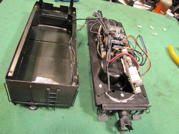
I bit the bullet and ended up buying one of the Atlas O 0-6-0 steam switchers...  For my preferred railroad I had been watching for the two options available that have been made previously, either Atlas or MTH, and it turned out that after a long time watching an Atlas engine came up first and for a pretty decent price too.  It appears to be nearly new if not actually new since the wheels and rollers looked pristine as did the rest of the model.  Of course I went into this knowing these had some issues such as the drawbar and tether setup which was confirmed when I got it on the track.  I've been considering trying to make some changes and improvements to the engine as a winter project and have a few questions for anyone out there who has had one of these apart...

First, what are the "watch outs" or hints for getting the tender and locomotive apart, as in removing the shells?  I've poked around on the tender a bit and it appears there are four screws from the bottom, one in each corner.  The bottom didn't seem to budge though and I was hesitant to get too tough with it right away.  Looking closely at the tender there almost appears to be a trace of adhesive on the bottom front and rear of the tank - did they do anything strange like both glue and screw the tender shell to the tender frame?

For the engine itself I've only seen a couple casual references made to it being difficult to disassemble but without much in the way of details beyond that...  What should I look for, and likewise watch out for getting the boiler and cab off to expose the internals?

One more question for now, the manual makes no mention about the lights on the engine...  I'm not sure if my eyes are deceiving me, but they almost appear to be LED's?  Either way, can anyone confirm the voltage of the headlight, tender, and cab lights?

Last edited by CCTSteam
Original Post

Replies sorted oldest to newest

I spent a little time this evening tinkering and starting to dig into this engine.  The tender actually ended up coming apart more easily than I was initially afraid of.  And I discovered that what I thought was adhesive was just a little "goo" that had bled into the joint between the shell of the tender and the frame from foam strips attached to the inner lower edge of the shell.  So the tender is apart and I'm able to take stock of what's inside.

The engine is being a little more challenging.  I removed two screws beneath the cab and one under the cylinder saddle and the lower part of the engine seemed to come loose.  The cylinder end is totally free but something is hanging up getting the motor end out of the firebox.  It only seems to pull out about 1/4" before hanging up.  After trying various ways of tilting and wiggling it I decided to set it down and come back to it later.

If anyone has any hints for whatever is binding up the motor end from coming out of the firebox I'd be interested to know!

Last edited by Rich Melvin

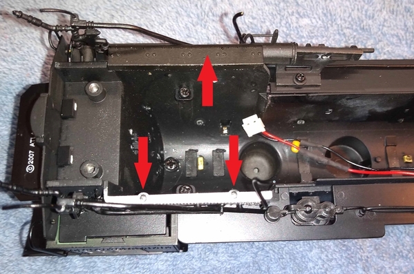
So I've done some more tinkering and reached a breakthrough...  The secret to getting the engines apart and the motor out of the firebox area is the two ashpan pieces on the bottom edge of both sides of the firebox.  I eventually figured out that these are not cast solid with the sides of the firebox, and are actually just a firm press fit.  Each of the ashpan sides has two pins, and there are two matching holes on the inside of the firebox sides they press in to.  They can be gently, but firmly pulled off, and afterwards the lower chassis and motor separate easily.  Below is a picture showing one of the ashpan sides in place, and the press fit holes on the other side where the ashpan is removed.

Atlas060_Firebox_Bottom

Attachments

Images (1)
  • Atlas060_Firebox_Bottom

I've found that when I run into one like this, setting it aside for a spell and coming back to it usually results in progress.  There are also many times where just the trim where railings or piping come through the shell block the chassis from separating.  You just have to look for them and deal with them once you figure out what is holding up the works.  On larger articulated models, many times the front articulated power truck has to come off first.

I too have one of these steamers. She runs very well at low speeds as a switcher should. I would like to dead rail it in the future. This loco has been dormant in its box since moving to new home and in-progress layout. There is not much info on this loco. Please keep us posted. Jim at Atlas’ parts dept. may have info if you can get to him. He has always helped me in the past.

Keep us posted. John’s advice (above) is dead on.

Larry

I've picked this engine up and set it down a number of times so far, and I definitely believe in the idea of stepping away from something like this when I seem to reach a dead end or frustration starts to set in...  I'd much rather take my time and come back with a fresh mind than end up breaking something.  At the same time I enjoy a good challenge sometimes, and this seemed like a good one to tinker with and see if I could improve some of the functional weaknesses these have...

When I ran it a few times after receiving it I was definitely impressed with how smooth and nice it ran including slowly.  But it's weaknesses were readily apparent too...  The tether / drawbar arrangement, less than impressive sounds, and it also seemed like the tender trucks were really stiff to swivel and turn.   These are all things I'm looking at trying to improve upon.  The disassembly process has been really interesting so far, seeing exactly how these are put together.  I did a lot of searching thinking someone has surely done a writeup or video of upgrading these and fixing some of their problems, but was surprised I was able to find relatively little about these in that regard.

So one of the things I'm looking at is an electronics upgrade, most likely with current ERR parts such as the Cruise Commander and Railsounds.  One of the other things I'm looking at is using the Chuff Generator and Super Chuffer from Hennings and John.

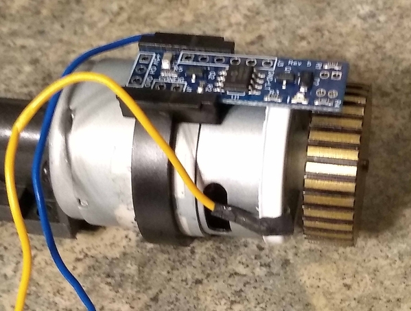
Examining the motor closer I was impressed to see that the flywheel has the tach stripes machined right on it as shown in the picture below.  The black stripes are recessed slightly from the OD of the flywheel and painted black.  A black plastic band is clamped around the motor which held the original flywheel tach sensor.  As it turns out the Chuff Generator fits within this sensor holder like the original sensor did, though it'll have to be repositioned a bit.

Atlas060_MotorFlywheelSens

So now for the question I hope John can answer...  The tach tape provided with the Chuff Generator has stripes that are about 0.100" wide, compared to the stripes on the flywheel which are about 0.050" wide.  Will the Chuff Generator work with the narrower stripes on the flywheel or does is it need the wider stripes to work?

Attachments

Images (1)
  • Atlas060_MotorFlywheelSens

John - Appreciate the reply and answering that question...  It's good to know that the Chuff Generator should be able to use the existing flywheel.

Larry - There are some parts available for these on the Atlas website O Master Locomotive Spare Parts, O Scale Locomotive Spare Parts | Atlas Model Railroad (atlasrr.com) .  I looked around just to see what they might have before starting to take things apart.  As for room, it's pretty tight as you might imagine...

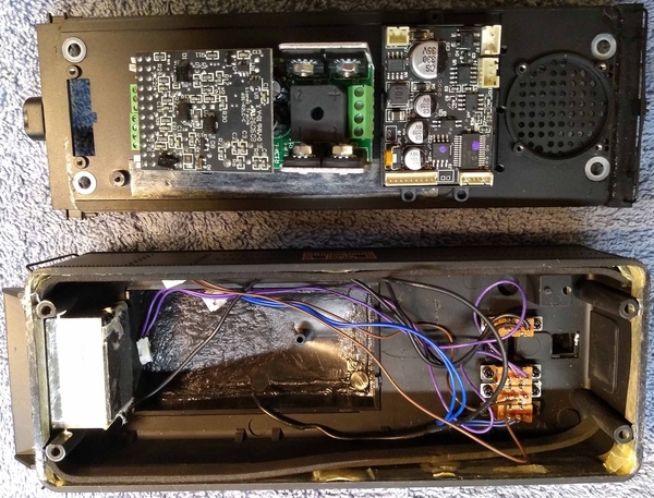
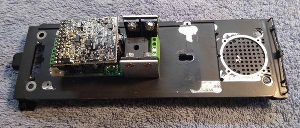
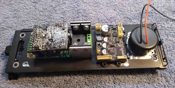
Getting the ERR boards into the tender is going to be a pretty tight fit.  So far though it appears that a Cruise Commander will fit if located so that it's under the raised coal bunker.  I don't think there's enough vertical height to stack the Railsounds board on top though.  I'm thinking that will have to be behind the Cruise Commander but will have to be laid flat or nearly so since it appears to be just a hair too tall to clear the tender shell if stood on its side.  This then makes it a challenge to fit the included speaker from the ERR Railsounds kit in the rear of the tender...  I've been looking around at some alternative speakers such as oval / rectangular that could allow a little more room.  Vertical clearance is tight in the rear of the tender as well because of the switches in the water hatch which I'd like to retain, and also a cast in square post that served as the mount for the original volume pot.  Without the volume pot, there's only about 1/2" to maybe about 0.600" vertical space below the switches.

Atlas060_TenderApart

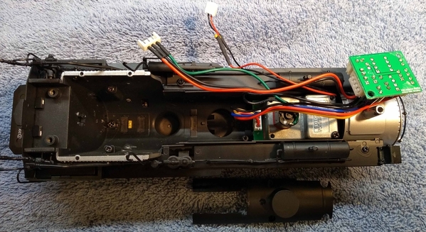
Everything is snug in the engine too...  Of course the front end is filled with the smoke unit.  The unit is set behind the stack with a plastic piece attached to the smoke unit outlet over to the bottom of the stack.  The smoke unit control board was located in the smokebox approximately as shown in the picture.  Just behind the smoke unit you'll notice a mounting post which is where another board was mounted that provided the power for the cab and firebox lights.  I'm continuing to study this but as of now my thinking is to re-use the existing smoke unit and put the Super Chuffer board either in the smokebox, or behind the smoke unit below the steam dome.  It's definitely nice that the Super Chuffer board is more compact than the existing board.  One interesting thing to note is that the boiler bottom trim piece is actually attached to the smoke unit itself at the two holes to the left of the fan motor - it's not attached anywhere else.

Atlas060_BoilerApart

Attachments

Images (2)
  • Atlas060_TenderApart
  • Atlas060_BoilerApart

You can obviously trim off the screw holes on the sound board holder, that helps a little.

For speakers, check with Digikey, they have a decent assortment.  I narrowed down the search as to size, power, and impedance.  You will have to further narrow it down to the exact diameter and height you need as I can't do that.

8 Ohm Small Speakers at Digikey

Appreciate the suggestion John...  Digikey does indeed have a wide variety of speakers to choose from.  I did a lot of exploring there and ended up looking at some of the rectangular / oval speakers, and ordered a few to try out:

CMS-402811-28SP, SC400308-1, and SC400608-1

I rigged up a little test to get power to the Cruise Commander and the Railsounds Commander boards so I could test each speaker against the one that came with the Railsounds Commander kit and sample the various sounds - chuffs, whistle, bell, crew / tower talk, etc.  After doing so I was pretty surprised with how good all 3 of these speakers sounded, and to my ears each was at least as good as the speaker from the Railsounds Commander kit, and maybe even slightly better.  And each was an improvement over the original speaker which didn't impress me much at all when I ran it a few times.

For small tenders, I've had really good luck with Soundtraxx 27 mm (1.06") round "High Bass" speakers with enclosures (enclosure sold separately).  The HO guys use these with DCC sound systems and the sound (with enclosure) is really good.  Here's one of mine in a small tender from a 3rd Rail H6sb 2-8-0.

IMG_2151 small

Attachments

Images (1)
  • IMG_2151 small

I thought I'd share a little more of what I've been up to on this...  I followed the advice John and Bob gave in the previous couple posts and did a little more experimenting.  This meant buying a few more speakers to test, and baffles, putting them in the tender with the shell on top, and seeing what I thought of them compared to the RS Commander speaker and baffle (which does indeed improve the sound) even if it's a little too big for this project.  Overall the baffle didn't seem to make too much difference with the oval speaker I was leaning toward previously.  I think the one I'm going to go with is the same as Bob recommended though it isn't Sountraxx brand - but is 27mm diameter with baffle and looks like it's probably the same speaker.  The most interesting speaker I tested, and probably my second place choice was one from Scale Sound Systems.  The speaker was one from their "Full Force Range" of Steam Series Speakers.

After settling on a speaker I turned my attention to the tender frame.  I wanted to get rid of the raised lip where the original speaker attached to, the mounting lugs for the original TAS boards, and fully flatten out the area in front of the speaker.  I did this with an endmill in my drill press and also located and drilled the mounting hole for the Cruise Commander.  The result is shown in the pictures below.

Atlas060_TenderFrameMilledAtlas060_TenderFrameMilled&Parts

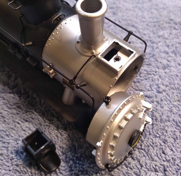
In the midst of all this I kept trying to figure out how to get the light out of the headlight on the engine since I wanted to swap that out too.  I didn't care for the colored LED and for my taste would rather have a warm white LED instead.  Eventually I figured out that the headlight on these engines is simply a press fit on top of the smokebox - gently pressing up on the hood over the lens will pop it loose.  This also exposes the screw that holds the smokebox front in place which will make it easier to work in that area and verify the smoke unit is properly aligned after it goes back in.

Atlas060_HeadlightSmokebox

Attachments

Images (3)
  • Atlas060_TenderFrameMilled
  • Atlas060_TenderFrameMilled&Parts
  • Atlas060_HeadlightSmokebox

Hey there CCT, how is your project going? Have you got her up and running? I sure appreciate you sharing the journey. I found the parts at Atlas to convert the 3-rail couplers to scale. Just have to terminate the wires going to the removed couplers. I feel I have a challenge adding a battery pack to the tender along with a DCC receiver and Controller. But after removing the TMCC hardware there’s a good chance it can work.

Larry

Larry - the project is definitely still "in the works" you could say, and I've been tinkering with it a little off and on...  I actually did a little testing on the bench on curved track sections to get an idea of how the reconfigured tether(s) look like they'll work.  It looks like I'm going to stick with the same basic concept as the original, that is the two sets of wires on either side of the drawbar from the engine up to the common plug on the bottom of the tender.  I'm going to use more flexible wire though, and also think I'll use woven mesh wrapping on them instead of heat shrink tubing.  All of this combined with the fact that I'm going to have fewer wires than the original 14 will make the tether more flexible.  I had to order different connectors and an appropriate crimper which I didn't have before to create the new tether.  With the realization that the headlights come off as easy as they do, I'm also considering changing to the CB&Q style "cuckoo clock" lights and am on the verge of placing an order with Precision Scale to get those.  Lastly I'm waiting on some new ring terminals to arrive for the electrical pickups on the tender trucks so I can rewire those with more flexible wire as well.  The original wires seemed a little stiff and the trucks didn't seem to swivel as well I'd like, so I figured why not go ahead and try to improve that while I'm at all of this.  Hopefully in the next couple weeks or so I'll have more progess and some pictures to share of how things are going together.

Add Reply

Post

OGR Publishing, Inc., 1310 Eastside Centre Ct, Suite 6, Mountain Home, AR 72653
800-980-OGRR (6477)
www.ogaugerr.com

×
×
×
×
Link copied to your clipboard.
×
×