Soon I'll be attaching some feed wires to my new Lionel O gauge tubular track.

It is not laid down yet, so I'll be able to do it at my bench.

Over the years I have seen the wire attached 3 different ways:

1. The under side of the rail is spread apart momentarily with a screw driver and the bare, tinned end of the feeder wire is inserted in the gap. Screwdriver is removed and heat    is applied to reflow the solder.

2. Similar, except a ring or spade terminal is applied to the feeder wire and inserted in the gap. Solder then applied to terminal/ track.

3. The wire is attached to the side of the rail with solder only.

I'd like to hear what you guys are doing with regard to feeder wire attachment.

Thank you in advance.

Rich

LIONEL6457

Original Post

Replies sorted oldest to newest

ADCX Rob posted:

I use the "RIGHT ANGLE MALE FLAG TAB QUICK DISCONNECTS" where I don't have a nearby 022/711(or similar - K-Line, eg.) switch, RCS/UCS/1019 or similar, to make the power connection to that section of track.

I tried to find these when I was building my Gargraves based layout and there were none to be found.  This is a good option as the wires don't stick straight out from the rails.  But I still think nothing beats a good solder joint.

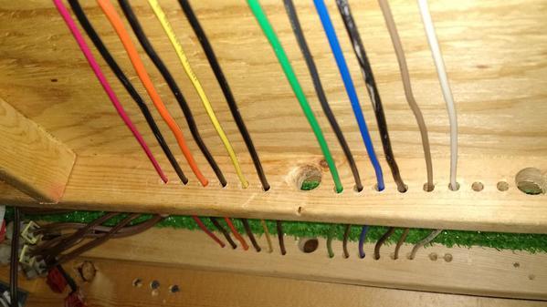
I have never split the rails open before soldering.  Once I have completed a loose layout of the track, I drill holes through the astroturf carpet and through the plywood.   I put a twisty tie or pipe cleaner in the hole and bend it 90 degrees so it wont fall through.  I then take up the pieces of track that are going to get the power connections and clean a 1 inch area under the rails.  I then tin the track with solder on my bench.  I use 16 gauge stranded wire for track power.  That wire is soldered to the pieces of the track and then the wires are fed down through the drilled holes.  The 16 gauge wires are then connected to the buss wire that runs under the layout plywood.  IMG_20150826_185119154

Then I just attach the pigtails to the appropriate buss wire.  Different colors for different track or different voltage levels for accessory power.  I space the pigtail connections about 1 inch apart so they can't short out

IMG_20150826_185329656

Attachments

Images (2)
  • IMG_20150826_185119154
  • IMG_20150826_185329656

Lets see...

1. The under side of the rail is spread apart momentarily with a screw driver and the bare, tinned end of the feeder wire is inserted in the gap. Screwdriver is removed and heat    is applied to reflow the solder.

I think this would be best/easiest, as you're effectively using the rail as a third hand to hold the wire in place.  It isn't going to make any better of a connection than soldering without the wire pinched in the rail, but may make it easier to get a good solder connection in the first place.  I think you'll probably need to add more solder than just the tinned end of the wire holds.  

2. Similar, except a ring or spade terminal is applied to the feeder wire and inserted in the gap. Solder then applied to terminal/ track.

I don't see any point in this method.  If you are using a crimp on connector on the wire, there isn't really any point in wasting time making a solid, soldered connection of the terminal to the track, you still have a mechanical connection in the system.  and if you are soldering the wire to the connecter as well, you are just adding an extra step.  the connector doesn't provide any benefit with a soldered connection.  (see my 'method 4'' below).

3. The wire is attached to the side of the rail with solder only.

There is nothing wrong with this one, but hidden wires under the rail tend to look better... because you can't see them.  If you've got your track laid down and find you need to add a feed somewhere this is probably the best way to go.  

Method 4:  this is the non soldered version of 1 and 2 above, and where I think #2 came from in the first place.   pry the rail apart enough to poke a wire in and then remove the screwdriver, and the rail will pinch to hold the wire.  All of my layouts up to now have used this method with no problems, however on my next build I do plan to do my wiring much neater and to solder the connections.  I think the use of connectors on the end comes from this where you can likely bypass needing a screwdriver to pry the rail open, as an o ring or such is sturdy enough to force into the rail.  the connector will also hold up better over time than just a wire pinched in the rail as it is much less likely to break from the tight pinching.  

JGL

I solder my feeder wires to the underside of the track.  I drill a hole under where the wire is located and pull the wire through.  Soldering makes a solid fool proof connection.  If you run DCS as I do you need good track connection, I solder everything.  Where two sections of track meet, I solder the center rail together for solid connections.

Add Reply

Post

OGR Publishing, Inc., 1310 Eastside Centre Ct, Suite 6, Mountain Home, AR 72653
800-980-OGRR (6477)
www.ogaugerr.com

×
×
×
×
Link copied to your clipboard.
×
×