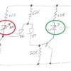
Looking for some ideas.

It is simple to isolate one rail so when the trains are in the hidden track; hook this up to a Evans Designs universal LED; that work on AC or DC and 19 volts from the rails;

http://www.modeltrainsoftware.com/bl-212.html

When the train hits the hidden track it completes the circuit to light the LED as on a signal or display panel.

But it would be nice to also have the feature of the signal showing red occupied and green when clear. I guess I could add in a 24 volt DPDT relay but want to keep it simple and cheap for a # of signals. Any other suggestions?

The sensors like MTH do not always work that well for long tracks and are pricey for a large # of them. Any other suggestions?

Original Post

Replies sorted oldest to newest

There are a number of ways to do this, but I think the relay is the easiest, especially if you have your heart set on the LEDs you linked.  If you're at all interested in getting a little more complex you could use some transistors and roll your own circuit and power source to use off the shelf LEDs.  

For relays, the Chinese modules are quite cost effective, at about a buck each, or $6 for a board with 8 relays.  Another source for super inexpensive relays is an auto salvage yard.  I've asked to pull the relays before cars are crushed and walked out with a couple dozen relays for between $5 and free.  

JGL

Define cheap.  Relays are extremely cost effective generally under $5 each, maybe even less, it has been a while since I purchased any.  That is the most reliable way to accomplish your task.  By the way, I use them on all of my hidden return loops just as you describe.  It ensures that when I power up the layout I can see at a glance if I left anything in the loop during the last session.  I never went the chinese route, but radio shack has DC micro relays that work just fine.

kj356 posted:

Looking for some ideas.

It is simple to isolate one rail so when the trains are in the hidden track; hook this up to a Evans Designs universal LED; that work on AC or DC and 19 volts from the rails;

http://www.modeltrainsoftware.com/bl-212.html

When the train hits the hidden track it completes the circuit to light the LED as on a signal or display panel.

But it would be nice to also have the feature of the signal showing red occupied and green when clear. I guess I could add in a 24 volt DPDT relay but want to keep it simple and cheap for a # of signals. Any other suggestions?

The sensors like MTH do not always work that well for long tracks and are pricey for a large # of them. Any other suggestions?

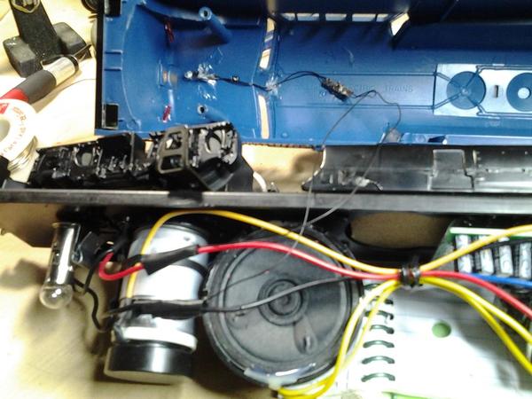
I used Model Train Software LEDs on two of my Williams engines and one of my station platforms that didn't come with lights. As far as the block signals, I used a double pull/double throw relay with a bridge rectifier and a capaciter to prevent studdering when the train enters the blocked section.


Williams BL-2Williams U33CWilliams Lehigh ValleyWilliams BL-2

Attachments

Images (4)
  • Williams BL-2
  • Williams U33C
  • Williams Lehigh Valley
  • Williams BL-2
Last edited by DennyM

As above, define cheap, define simple.  And how many signals are you talking about when you say "a # of"?

It appears the Evans LEDs are about $3 each

You can get 12V DC pre-wired LEDs in red, green, and other colors on eBay for about 20 cents each (free shipping from Asia).  Pre-wired means you don't have to fuss with resistor selection and soldering...but you now need a source of 12V DC.

pre-wired 12v led

You can get a 12V DC adapter/wall-wart on eBay for about $2.  And if you don't want to mess with splicing/stripping the barrel plug you can get an adapter for about 50 cents to make the + and - voltage available on a screw-terminal.

12v dc wall wart and adapter

Now that you have a separate/isolated supply of 12V DC available, you can switch that on your insulated rail section to drive 12V DC relays.  For example, here's a module of 4 relays with screw-terminal inputs and outputs for just over $4...about $1 per relay.  Note the use of screw-terminals which can simplify assembly..."loose" relays require soldering or those that offer companion relay-sockets are not cheap.

kj356 4 channel relay screw terminal inputs

Sure there are some i's to dot and t's to cross but I think this can be done at the "module" level without messing at the component level (transistors, resistors, etc.).  The component level would be cheaper for sure, but would involve soldering and working with small parts which is not in everyone's comfort zone.

After all the votes are cast, if you would like to pursue this approach I will sketch out a hook-up diagram for you.

Attachments

Images (3)
  • pre-wired 12v led
  • 12v dc wall wart and adapter
  • kj356 4 channel relay screw terminal inputs
Last edited by stan2004

Stan,

If I were to use the prewired, 12volt LED's you mentioned above, as interior lighting in a passenger car...under a TMCC environment (18 volts AC)...is it an over simplification just to add a resistor to the + lead to reduce the voltage?

(Assuming of course, the switching of the AC cycle would be two fast for the naked eye to detect  in the LED.)

Would that generate to much heat?

Seems like a cost effective way.

I am guessing prewired 12volts are more standard than say 18 or  20volt for LED's...

Or did my assumption make an ........ out of me

mike g. posted:

Hi Stan, if he doesn't I sure would like a sketch of a hook-up diagram.


Will do...but first I'd like the OP to chime in with any additional info on his application (# of signals, etc.) in case I can also make the drawing relevant to him!

Desert Railer posted:

If I were to use the prewired, 12volt LED's you mentioned above, as interior lighting in a passenger car...under a TMCC environment (18 volts AC)...is it an over simplification just to add a resistor to the + lead to reduce the voltage?

(Assuming of course, the switching of the AC cycle would be two fast for the naked eye to detect  in the LED.)

Would that generate to much heat?

Seems like a cost effective way.

I am guessing prewired 12volts are more standard than say 18 or  20volt for LED's...

By leaps and bounds the application for 12V DC pre-wired LEDs exceeds that for 18 or 20V applications!  The Evans LEDs at $3 each were clearly designed for the model train market...which is a drop in the ocean compared to the automotive market.

To answer your question at face-value, you could hook up the 12V DC pre-wired LED plus a resistor to TMCC 18V AC and it will work.  Some may/will say you need to add a diode to block the reverse voltage from the AC.  It's a your-mileage-may-vary since indeed LEDs have varying tolerance to this.  And yes, the LEDs will be flashing 60 times per second.  The ability for the naked eye to see this is also one of those your-mileage-may-vary situations.  I can see it (though not as annoying as when I had younger eyes).  To me it's a hard-to-describe strobing-like sensation akin to how fluorescent light "flicker" (before modern electronic ballasts) bother some. 

Heat will not be an issue.

However, I suggest you refer you to one of the many OGR threads on LED lighting in passenger cars which will steer you toward 12V DC LED strips.  The per-LED cost of those strips is 2 or 3 cents!  They are easier to mount than these discrete LEDs, they have wider illumination angles (smoother lighting in cars), and there are simple circuits (both DIY and pre-built) that handle flicker reduction (with a capacitor), adjustable brightness (with a trimmer pot), and so on.  I've read some guys get by driving these strips directly from 18V AC track votlage...but the consensus seems to be that by the time you open up the car to make the wiring modifications, it's a small step to add the extra 50 cents (or so) of parts to eliminate the 60 Hz strobing-effect.

Thanks for the suggestions; the advantage for the Evans AC/DC 19 volt LED's is that I can just use the track power very simple, and they do not interfere with the DCS signal and the local hobby shop has them in bunches cheaper.

Most other suggestions are adding in a lot of extra cost and complexity and wiring and possible issues with the DCS signal.

The 12 volt DPDT relays would need to be knocked down in power or have a separate circuit to work, suggestions above.

24 volt relays are a bit pricier and less available from the local electrical parts shop.


With the 12VDC relay, you can place a diode in series with the relay coil, and the relay will see about 12.7V off 18VAC track power.  This won't hurt the relay.  

You can also easily use a separate power supply for signals and their controls if you like.  You can share ground between the supplies with out problems in most cases, then the insulated track can switch the ground side to trigger devices powered off lower voltages.  This tends to be the easier method, as the 5 or 12 volt relay modules are far less expensive than any other method for new parts.  

JGL


JohnGaltLine posted:

With the 12VDC relay, you can place a diode in series with the relay coil, and the relay will see about 12.7V off 18VAC track power.  This won't hurt the relay. 

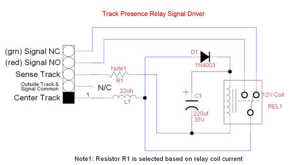
If you only use a diode most if not all 12VDC relays will chatter at 60 Hz.  Of course a capacitor placed after the diode solves this but this capacitance degrades the DCS signal.  But the capacitor charges up making the DC voltage at the relay too high so a resistor or other method of lowering the voltage is typically needed.  The capacitor also degrades the DCS signal so now the DCS 22uH choke/inductor must be added.  While all these parts only adds 25-50 cents, it can be an assembly hassle if soldering and working with small components is not in one's comfort zone.

This is what I use for track signal sensing.  I use relays salvaged from old PLC control panels, so the parts are very cheap.  I just whack these together on small chunks of wood for mounting under the layout.  It has the RF choke for DCS compatibility and the cap for killing the relay chatter.  If you don't want to use track power to activate the relay and drive the signal, you can just add a connection and drive them from separate power.  Since the relays and signals we use are very low power, I went the simple route.

Track Presence Relay Signal Driver

Attachments

Images (1)
  • Track Presence Relay Signal Driver

I really like the 4 channel module pointed out above, there are numerous solutions.  I was quite intimidated using relays at first, none of it made sense until the day the light came on (pun intended).  I did go the more expensive route, using block signals for occupancy detection.  That was a choice to make my layout a bit more interesting visually and accomplish the same task.  You will find this to be a fun and rewarding project.

It depends on what qualifies as "simple" and "cheap".  To each his own. 

So here's how to use the ~$1 per relay eBay modules with a 12V DC adapter (aka wall-wart).  Because relay and LED power is provided by this independent (electrically isolated) power source, there is NO effect on the DCS signal.  Note that the "-" output of the 12V adapter ties to the common outer rail.

isolated rail 4 channel red-green 12v

The $2 12V adapter has 1 Amp output capability so can power a dozen or so relays plus LEDs.  For a few dollars more you can get a 2 Amp, 3 Amp, etc. adapter if you have more channels.

There are 12V relay modules with a lower cost per relay but I show this one as it has screw-terminals on the inputs and outputs.  Some/most of the lower cost relay modules use so-called header pins on the inputs which mate with special sockets that most guys don't have.

I don't know how cheap you can get the Evans LEDs ($3 on their website) when bought in quantity at a LHS, but hard to believe they get down to 15-20 cents for pre-wired 12V LEDs on eBay.  The Evans LEDs can be used with the above relay method.

Attachments

Images (1)
  • isolated rail 4 channel red-green 12v

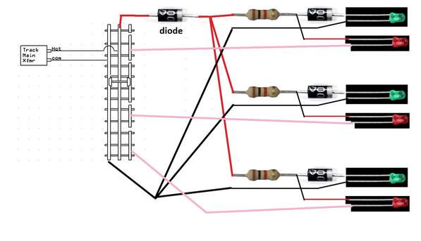
OK, not sure about the "flip-flop" part, but "starving the green LED" is commonly used to "dim" one of two LEDs in an insulated-rail section.  For example:

resistor 1k

So normally the green LEDs get power thru the 1k resistor.  When the insulated rail section is shorted, the red LED turns on and because its "on" voltage is only about 2V DC, it steals all the current and thereby starves the green LED of voltage so it effectively turns off.  A green LED is typically on at around 3V DC and putting an extra diode as shown makes it more like a 3.5V LED.  Increasing the difference between the red LED "on" voltage and green LED "on" voltage makes for a "crisper" transition.

I suspect the bulb dimming method you're referring to employs some kind of similar starving mechanism.

I don't know if there are any off-the-shelf solutions and I've come to appreciate that anything that involves fiddling at the component level, selecting resistor values, wattage ratings, diode types, soldering, etc., is not "simple."

Attachments

Images (1)
  • resistor 1k
Last edited by stan2004

Hi Stan-

A fairly popular scheme for incandescent lamps in the past was "voltage starving." I don't have a drawing program on this computer, but picture a high-current red lamp (or parallel combination of lamps and resistors) in series with a low current green lamp. Normally, the current through the higher-current lamp is limited by the lower current lamp, so the low current one glows and the high one stays dark. If the low current lamp is now shorted by an insulated rail, the full supply voltage appears across the high-current lamp and the low current one is extinguished because it is short circuited. Works fine, but you need to understand enough to choose appropriate lamps and resistors and mount them.

As far as your "current starving" schemes for LEDs, I have never gotten them to actually work well on the layout without a great deal of pain.Unless you have a dedicated power supply and wiring for each signal, stray voltage drops through the conductors common to the signal and power circuits cause all kinds of trouble. It is extremely easy to get a 1 - 2 volt difference between different ground points on most layouts, and that raises havoc with the current starving. I have done it, but IMHO it is just as easy to use a relay. 

Just my $.02 worth. NO refunds.

Thank you for the explanation of the incandescent method.  As for the LED approach, I'd think you wouldn't have a problem with ground shifts around the layout if you localize the red and green "grounds" at their point of use.  I realize now I should have drawn the diagram differently with the Green and Red "grounds" for each section coming from the same point.  Or I think that's what you're referring to...

Yes, localizing the connections as you show would be a great help, but I was using a common fixed voltage supply on multiple signals and brought the grounds back to the fixed voltage supply, not the track (other than the control rail, of course.) Just a standard I have adopted, I don't use the track as a conductor for any other circuit. Maybe I will try it as you show as a science project.


Agreed, starvation techniques may not fall in the "simple" category for everyone.  Your recent thread on the K-Line red/green LED signal head I'd say is the closest thing to "simple" since it comes pre-wired with 3 wires for center-rail, outer-rail, and control-rail.  But not "cheap" and apparently difficult to find.

https://ogrforum.ogaugerr.com/t...-track-signal-bridge

Thanks to your excellent investigative journalism (aka reverse engineering ) I copy your work below for the record.  If going the DIY route this circuit does not depend on starvation and hence perhaps more of a sure thing with flexibility to use arbitrary LED colors and such.

k-line red green LED signal head

Attachments

Images (1)
  • k-line red green LED signal head

Hi Stan-

Well, what actually got me going on this was the desire to re-purpose old Lionel signals that used the nearly extinct 2 pin lamps, #12 and #19. It happens that the "sockets' Lionel used for these are a very good match for the square leads on 5mm LEDS - see photos. You of course need to change the electrics, so I was trying to come up with a simple DIY way to do an LED and a single-control conversion as one project. But, it is just short of being acceptable for DIYers at this point.

See photos - a couple LEDS, a couple PC board standoffs, and for a buck worth of parts all the mechanical stuff is done! 

Attachments

Images (2)
  • IMG_1043
  • IMG_1044
Last edited by PLCProf

What luck that the LED lead spacing seems to be identical to the original bulbs!  Yup, the component approach is for the determined DIY-er.  But one benefit of the component approach (vs. relay) is you can fit the electrics in a cavity under the rail-bed if one uses Fastrack, Realtrax, or the like.

Re-visiting "simple", I was thinking about the OP's comment a "new" 12V DC power adapter adds complexity.  I can see that reasoning, but if the application is to indicate block occupancy on a control panel, I'd think many control panels could benefit from having 12V DC available for other indication/lighting functions.  In other words, if you have a 12V DC local supply at the control panel, you only need to run 1 wire back per remote/distant insulated-rail section to the control panel.  I'd think that falls under the "simple" category!

True enough, but the concept of "simple" varies. To a lot of non-electrical types, it is important to have a correspondence between the physical and electrical arrangement of things. The simplicity of the circuit never enters into it. 

My control panel is electrically simple, but many people can't deal with it. Here is my accessory wiring strategy-

1. All switches and buttons on the control panel pull to ground - no exceptions. I have 20 controls on the panel but only 21 wires; one is common to all switches and buttons.. Accessory ground is common to track outer rail. This is nice because I can add a manual control to any insulated rail signal with 1 wire and no fuss.

2. There are 3 bus strips for supply voltages, 12 VAC, 12 VDC, 16 VAC. There is an additional ground bus for continuously burning lights. Most everything works on DC except those items that specifically need AC such as vibrotor stuff, Fastrack switches, some electronics like those K-Line signal bridges previously discussed. DC supply is a commercial Samlex switcher, 23 amps regulated. Beats the pants off ANY train transformer as far as regulation goes.

3. All accessories have 2 wire power circuits to the control panel. All hots and common originate at the control panel. No track returns. Very little "bus" wiring.

This makes it extremely simple to change accessory connections. The control switch wiring is totally independent of the supply voltage, because all control switches work to ground. The "hot" wire of each accessory goes to the correct voltage bus, the common side connects to the desired switch. Changing the voltage or moving to a different switch is a quick 1-wire change. But, I am forever told that it won't work or it is unsafe because i'm mixing AC and DC, or I can't phase a DC supply with AC supplies, or it is not safe to put a switch in the common, etc. etc. etc.

Simplicity is in the eye of the beholder.


Add Reply

Post

OGR Publishing, Inc., 1310 Eastside Centre Ct, Suite 6, Mountain Home, AR 72653
800-980-OGRR (6477)
www.ogaugerr.com

×
×
×
×
Link copied to your clipboard.
×
×