


The structures coming out of this topic have been so great I have been reluctant to say this. Am I the only one who would have found this all more enjoyable and easier to follow if it had been broken into multiple threads rather than all being in one long running topic?
@Bill N posted:The structures coming out of this topic have been so great I have been reluctant to say this. Am I the only one who would have found this all more enjoyable and easier to follow if it had been broken into multiple threads rather than all being in one long running topic?
Nah!
Think of it as a James Joyce experience. ![]()
I have been following Myles for years. Personally, I like the single thread. I subscribe to it and it lets me know what Myles is up to next.
Bill N I thought about your suggestion while eating lunch. I will have to say I am with Pete and Pat. I too have been following for years. The only thing I can think of that may be lacking in Myles' approach is that someone who may pass by the topic but is interested in 3D printing may not realize they could learn a lot and contribute as well.
I love when there's a lot of comments to which to respond...
I did actually do a separate thread on building the substation back in 2014. Anyone know where it is? Nobody? Anybody? Bueller? I thought so. I can't even find it easily. That's the trouble with doing each sub-project as a separate thread. It's great when you're actually writing it, but then it gets lost. I've thought about both of these approaches.
When I post to other forums for some of the plastic kit projects, I do them as separate entries, but they don't relate to one another. They are discrete events. In the case of this model railroad, having it as a single VERY long thread provides context for the whole deal. It also lets the intrepid reader to go back and read the whole story. I know. I've done that a couple times. It is enlightening to me to re-live the experience. Otherwise, all the work just fades into history. I look at all the stuff on the train table now and it's good to re-visit it and appreciate just what effort went into making it all happen. I want my readers to be able to do that too. If they ever want to do it on their own and not just have the vicarious enjoyment of reading about it, they have a pretty detailed roadmap to follow on how to go about it. After all, in this instance, it is ultimately about building a model railroad, not just building some structure dioramas. All of my projects were destined to be on the railroad, not as stand-alone entities. I actually wish that the first six pages on the first thread on the layout infrastructure build was part of this same thread. This one starts with scenery because of how OGRR divided the topics, but it's really one long story.
Now onto today's progress.
We had a lovely October day with the temps near 80 and very little wind so it was time to paint all the architectural detail parts outside. I stuck all of them to a large piece of cardboard with rolled wide 3M blue tape. Some of these parts needed painting on both sides. My plan was to spray the first side, let it dry enough to handle and then turn them over.

I used Rust-Oleum gloss white primer/top coat paint. I wanted the details to be gloss white and was going to prime them with Tamiya white primer and then airbrush Tamiya gloss white. I didn't realize that I had the Rust-Oleum white on the shelf and finding it eliminated a step.
This pic was after the first side was painted. I set SIRI on my iPhone for 25 minutes (the recommended drying time for handling) and turned over the parts where the two sides weren't initially exposed. Between the masking that was exposed and the natural stickiness of the previously applied paint, I was able to stick the parts well enough to keep them from blowing away from the spray. That trash receptacle has seen a lot of paint jobs as you can see by it's multi]i-colored lid.

Here they all were painted.

Again I gave it all about a half hour to set up and then brought it all inside. I carefully removed all the parts from the masking and placed them to on the work table to fully cure. I won't be installing these for a couple of days. It's a lot of parts! I also did some touchup painting to the inside paint on the cupola.

I didn't paint the chimneys since they get a different treatment.
I finished the 2nd floor trim and then thought outside the box. Instead of gluing the stair case to the 1st floor which made installing the second floor much more difficult by not letting me put in that mid-wall, I found that I could effectively glue the stairs into the 2nd floor. It would drop straight down into proper position. In these images, I haven't glued it in yet. I'll do that tomorrow, but this really changes my routine. I was convinced that the stairs needed to be glued into the first floor.
I got the 2nd floor hall rail in place, but then had to go back (after taking this image) and re-glue the rear portion. It had broken loose which is why is slightly off plumb in the picture. There will be two key places to glue the staircase into the 2nd floor; the top of the entry closet and the long side of the 4th flight to the attic. I'm thinking about what kind of cement I'm going to use. I sort of leaning towards the contact cement dots that I used to glue the appliances to the appliance store floor. The crown molding is also in place in the 2nd floor hall. I painted the stairwell edges craft paint white. This paradigm shift means the 2nd floor plate can be made removable. That means I don't have to 3D print all the furniture now. I can space it out. Now that the doors are painted, they can be installed.

I exercised today and still got stuff done. Tomorrow is a full work session so watch out.
Attachments
Images (5)


Well?? The good thing is when I miss a bunch of posts is that I can come back here to one, and easily catch up. It's tuff to keep up, because he's always doing something. You can't turn away or you'll miss something.
So if he made different posts, I'd have to subscribe (to his posts) and check in every day, just with him?
However he chooses, I'm just glad he shares and responds. Way above the call of duty!!!
@Trainman2001 posted:I now drive all my LED lighting with CL2N3 LED drivers. They're terrific and solve the problem of finding the right current limiting resistor. You put anything from 5-90vdc in and out comes 20ma which LEDs love. The higher the imput voltage the more LEDs you can power in series sicne they each drop about 3VDC. They're not happy driving parallel circuits so after you've reached the series limit, you feed another CL2 and run another string.

You may have shared this? It maybe simple?
What is the circuit and any other parts needed to build this circuit?
I just looked it up on Mouser and see just the driver. Is that it?
Great job on all those parts!
The circuit is as simple as it can be.
The CL2 has three leads. The center lead is a dummy there for more secure mounting to a PCB. With the chip's flat side facing you, the left lead goes to supply and the right lead goes to the LED + lead. That's it. It takes the place of the current limiting resistor. You can string as many series LEDs as your voltage supply will take. Since each one drops about 3VDC, for a 12 VDC source you can string four LEDs. When you exceed that number, they will dim until you reach the threshold where they won't light. When you want to run more that four (in this instance) you need to start another series circuit in parallel with the first with its OWN CL2. They're cheap at about $0.25 each.
This is a GREAT thread! Can you also post a wiring diagram for my electronically-challenged brain.
Thank you!
Perhaps this image will help you. It's pretty simple.

I'm now designing a breakfront china cabinet. I'm going to print it as a front that will lay flat on the build plate and the cabinet portion that I may also print flat the same way. I will be able to glaze the cabinet front before gluing the two together. That would preserve all the wonderful frontal detail without any supports.
Before I could glue in the steps I had to do all the wiring for the 1st floor lighting. I came up with another idea yesterday when I was cutting out some of the wall paper. I realized that blank HP photo paper is a perfect gloss white that I could use for ceilings instead of painting them. I used this idea on the first floor ceiling and I like it.
I needed to route a wire trench into the ceiling for the chandelier LED leads. I set my Dremel router attachment to 1/2 the ceiling thickness and cut the trench.

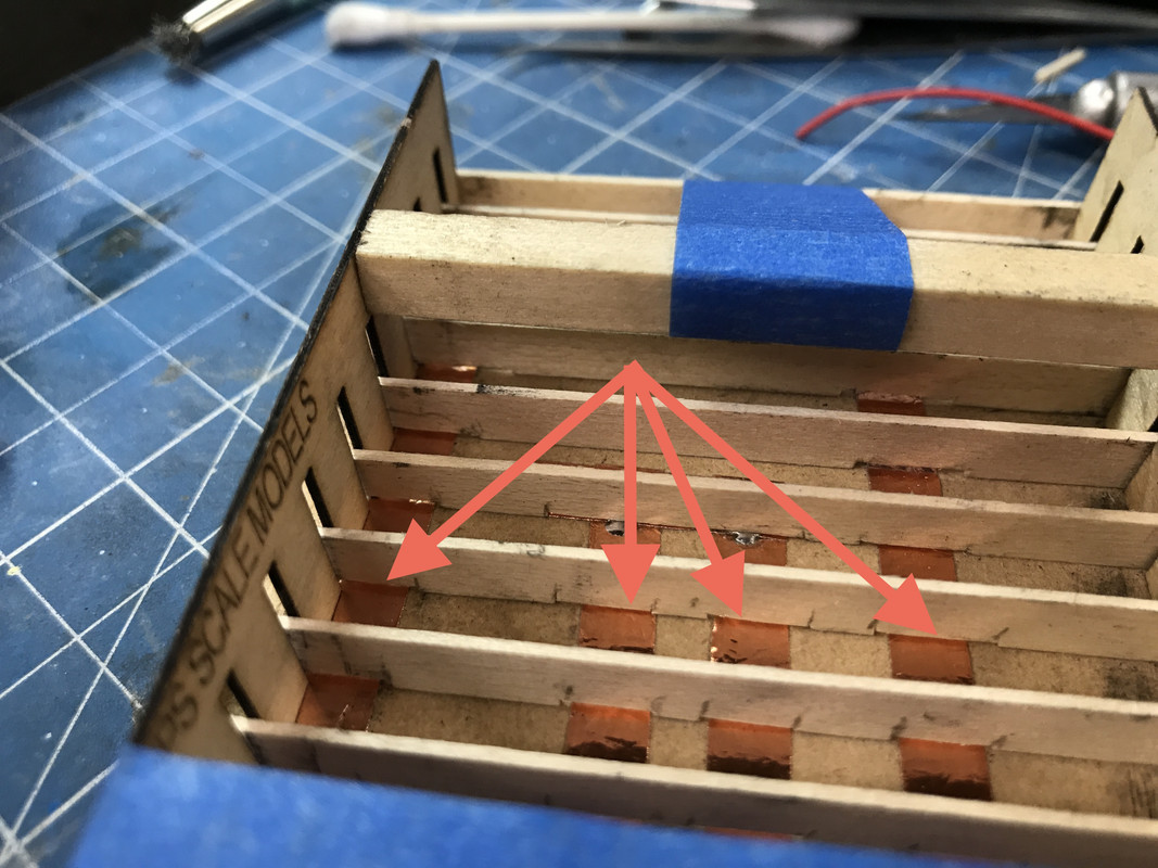
I located where I wanted the other surface-mount LEDs (SMLED) and laid down the copper foil. I was hoping to make it a single series circuit with one CL2 LED driver. I put 2 LEDs in the living room and one over the fireplace in the dining room plus the chandelier. I then further routed the trench so the chandelier leads could find their way to the foil.
I have using SMLEDs down to a science. I cut about a 1/32" gap in the foil, tin both sides and place the correctly-oriented LED over the gap. I heat the tinned solder next to the LED while keeping light pressure on the LED with a tweezers. When the solder flows and the LED drops into the puddle, I hold the heat on for just a few seconds more to insure fusion, remove the heat and continue holding the tweezers until it solidifies. I test the LEDs before putting them in the circuit and then test them again by isolating it by applying power to the foil on either side of the SMLED. I did find one where the solder hadn't fully fused and a little more heat was needed. You have to be careful. If you overheat these little gems it will kill them. I then test the series circuit as each LED is added.

The above circuit was my second iteration. I tested the entire circuit with the chandelier and the SMLEDs were dimming and the chandelier was just plain dull. The LED in the chandelier was drawing more than 3 volts so the series drop was adding up to more than my supply voltage of 12VDC. I split the circuit and added a second positive system with its own LED driver.
I then tested the building with the 2nd floor in place. It lit correctly.

Then I realized that I hadn't put the light in the foyer. And this was after I fully covered the ceiling with the white photopaper. Here was the living room side.

Here's the ceiling before the LED mod. The cutout for the lead attachment coincides with the entry hall closet. I opened up the closet roof so the power leads will pass through and down to the basement and out of the building. I pressed on the paper to emboss where the SMLEDs were and cut openings for them. The ceiling cover is held with PSA.

I opened the ceiling where the foyer light would go and cut a gap in the spot I noted on the circuit image above. The chandelier was the only LED on that branch so adding another didn't cause any problems. Now all the lights are on and bright. The foyer light is too bright and I'm going to put some paint on it so it dims a bit.

I need to secure the chandelier to the ceiling better than I have since it seem that the LED to spindle joint is failing (too much light leakage). The leads exiting under the closet door are forcing the staircase upward. When the wires are led down through a hole to the basement, the staircase will sit down better. The staircase is lifting the entire second floor as you can see by the crown molding gap. That will be better when all is in final location.
Attachments
Images (7)


Thanks for the wiring diagram. You have de-mystified it for me.
Thanks! I appreciate the clarity. I'm not always there on all the electrical designs. ![]()
Glad I could help.
Not much construction today, but a lot of activity this weekend. I decided to use photo methods to create the dining room table top. I photoed our own table, did some Corel PhotoPaint work to remove the highlights from the room lights and the cleaned up the shape and then dropped it into a shape that exactly matches the table I printed. I will print it both as a decal and on HP Photo Paper to see which one is better. I also found some 19th Century upholstery fabric and will cover the chair seats with it.

I'm also doing the same thing on the little Baker Server we have in the dining room. I've drawn that and will print it, and will use the images to create the surface. It will be on the new back wall in the dining room so you'll be looking at it head on.
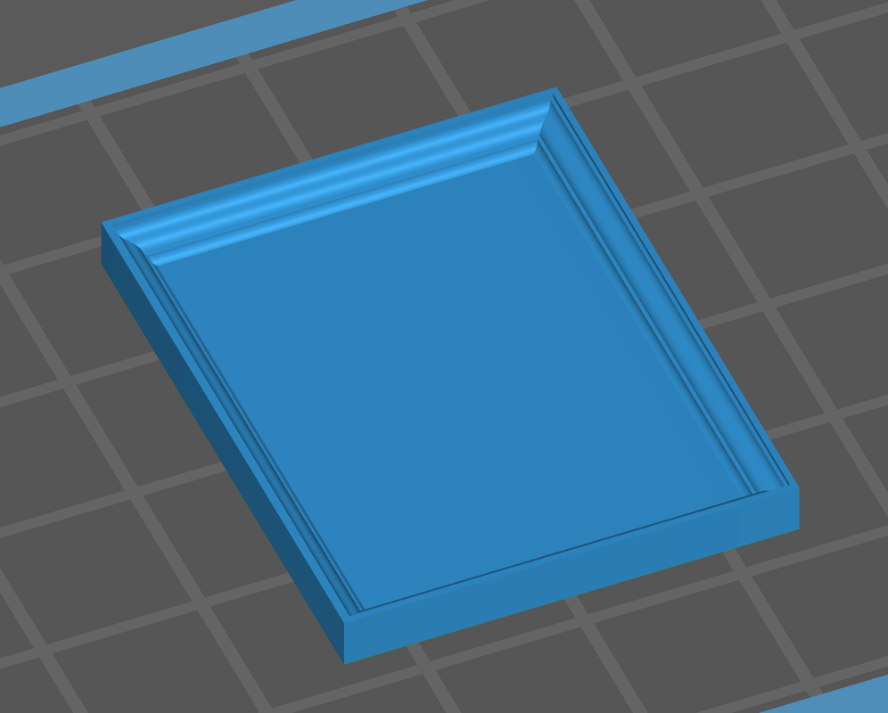
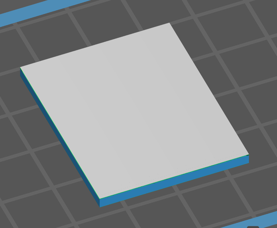
My China Cabinet print failed in a very strange way. It actually didn't fail. The sliced file already had the errors in it. The printer just did what it was told. The holes for the glazed portions closed up in the print. I went back and ran the animation of the sliced file and found that in the middle of the print a layer formed that closed the openings this ruined the print. I've re-set it at an angle with supports on the its back and will reprint it.

The back part of the cabinet printed perfectly.
I got the wiring and lighting done for the 2nd floor ceiling. Again, I had to split the circuit and drive it with CL2s in parallel. I'm assuming that these surface mount LEDs draw drop more than 3.0 VDC. When I split the circuit they were perfectly bright. I did put some gold paint over the foyer LED so it will not be so bright. I tied the two power ends of the CL2s together and soldered the hot sides together along with the attachment lead. They now lit as they should. I will have to check the specs on those LEDs to see what I'm missing.

I added a new partition wall to the dining room. I needed more wall space for the now-acquired furnishings. I removed the floor and wall coverings before gluing this piece is so it had solid MDF to which to glue.

Now onto the aforementioned furnishings.
I found on Thingaverse the same artist who did the scale furniture that was listed for sale on Shapeways. She had downloadable STL files. They were oversized, probably 1:32 or larger. I imported the STLs into SU and measured them. The file had the 1:1 size of the furniture in the file name. So for example, if the sofa was 56" wide, I scaled the STL file in SU to 56" so I knew what its 1:1 size would be. Then I reduced it by the O'scale .021 factor and got the O'scale version. When I calculated the actual difference in size between the Small Things file and the O'scale and found it needed to be reduced about 78%. ChiTuBox (the slicer) has a scaling feature, so instead of bringing all the files into SU to do the scaling, I just dropped the STLs into the Slicer and scaled it 78%. The artist was kind enough to have files that were already set up to plop onto the plate and print without supports. I just finished two sofas, a sofa table and a wing chair in one go. It's hardening as I write this.
Here's what the End Table array that I will print at one time (upside down of course). I like how she did the cabriole legs. I doubt she used SketchUp.

So with this find, plus what I'm drawing or already had, I now have all the furnishing I need and will be able to button up the building fully furnished. As a 19th building, I'm going to put the kitchen in the basement and therefore don't have to furnish one. I have a Chippendale sofa, a chaise sofa, two Chippendale love seats, sofa and coffee tables, all the end tables I'll need, nightstands and two beds (the same as I've used in the Tie Hacker's Cabin), a china cabinet, a console server, and the piece de resistance, a spiral staircase. All I need is decor and table lamps. Have to think about how to do those.
Yes! You read that correctly. I needed a way to get from the 2nd floor turret to the cupola. I'm assuming that if that space was usable there had to be a way to get up there. I searched the SU 3D Warehouse and came up empty. I then did a search on the STL sites and the same artist had a stone-looking version that would work in a pinch and was entirely printable.
I ended up drawing my own. My first version, while mechanically correctly, didn't have enough meat in it and therefore created a lot of islands in the print process forcing me to go with supports and this is the mess that would have printed. I would not have been able to extricate the part from the supports without damage.

I re-designed the stair to tie the steps to one another thereby eliminating the islands and (hopefully) printing without supports. This is how the revised version looks on the slicer. The only questionable areas will be the horizontal supports. They will be constrained with the vertical rods. This part is on the printer now and will be ready tomorrow. It's a 10 hour print job.

Here's how it will go into the building. The hardest part is cutting the access hole in the cupola floor. I'll have to rout that out and hope for the best. Wished I would have thought of this addition BEFORE gluing the cupola on the turret walls.

During the time I was writing all this up the furniture finished up. The main parts printed nicely, but the reason pre-coating can be a problem showed up. There are square holes in the undersides of the upholsetered pieces to accept the separate legs. The precoat formed a hard (but thin) layer over these openings and traped un-cured resin inside. I had to sand off the precoat layer to expose the holes which did form underneath as they should. The square lugs on the legs look bigger than the slots. I may have to trim the legs a bit to fit into these holes with some careful filing. Otherwise, they will do quite well.

This crazy project certainly has been a perfect example of "scope creep". I wasn't sure, when I started, about furnishing and now in one weekend I basically furnished the whole deal. I'm going to produce some grand artworks and this time I'm going to 3D print the picture frames. Again... nuts... right! But it keeps producing more proof of concept.
Attachments
Images (9)


Scope creep for sure, but it is certainly worth it! Wow!
I remember a lady from our church growing up who had a spiral staircase in her house. Her husband had designed the house and wanted minimum wasted space she said. I wonder how well she negotiated the stairs as she aged, she was probably only 60 when I did some yard work for her while in college.
Yes! I find them hard to negotiate and that was several years ago.
The redesign of the spiral stair worked! I haven't pulled it off the machine, but it looked like this when I checked it this morning. The vertical rods are a bit squirrely, but they should be okay. It will delicate until it gets post-cured. I'm still using the Tenacious/Elegoo resin mix which is imparting some flexibility. My theory that the flat rings would pull off the FEP by the vertical rods was correct. It looks perfectly formed.

Now all I have to do it punch that 1.5" hole through the bottom of the FDM PLA formed cupola. Because it's a thermoplastic, when I use the carbide router with the Dremel it immediately melts all around the cutter and it stops working. I have to run it at the lowest speed to have half a chance.
The lesson for today: Pay close attention to what the slicer shows you. If it looks like it's not going to work, don't print it. It won't work. Go back to the drawing board (or its digital analog) and redesign so it can be successfully printed. There's always a way.
A note about SketchUp: I made the individual step design a "Component". In SU, once something is a component, you can copy it an infinite number of times, but if you edit one item the change is instantly reflected in all its copies. It a very powerful and useful tool. So when I wanted to change the step design to attach each step to the one above, I only had to make the changes on one step and all the others changes as well. It turned a potentially tedious operation into relatively easy one.
Today's a full work day and the printer's going to be running the entire time. All the furniture should be printed by this time next week.
Attachments
Images (1)

The spiral staircase looks good. Have you thought of using a hole saw or a spade bit to drill the hole for the stairs? I have used spade bits on plexiglass for the club's control panel and it worked pretty good.
Thanks Pat! Yes, I thought of that, but the space is constrained. I explain in detail how I did cut the hole so read on.
As noted earlier, I did get a pretty full day in the shop. My full day starts around 1 p.m. I cleaned up the spiral stair and it was decent. There was some delamination under each step, but it wasn't a show-stopper.

What was almost a show-stopper was my original measurements. I made it too tall by one full step. It seemed to have fit in the SketchUp model, but not in the real-world one. What to do? I thought about re-drawing it correctly and reprinting, but I first tried to do some selective surgery to remove the extra step and associated railings.
In order to actually test it I had to cut that hole in the cupola floor. I was almost ready to purchase a MicroMark powered Sword Saw to do the plunge cut. I held off and went the 1/16" carbide router route. The FDM printed PLA plastic is tough, but melts. The carbide, even at my slowest Dremel speed quickly loaded up with melted plastic. I found I could plunge the running cutter into a wooden plank and melt and fling the plastic off so I could continue cutting.
I first had to knock off the reinforcing ribs, scribe the circle and start cutting. After I opened up the rough hole I finished it with a sanding drum, again at the slowest speed. I used a chisel pointed dividers to scribe the circle.

And here's the hole opened out before sanding.

Here's how the incorrect stair looked when installed in the opening.

I used the Dremel with a diamond coated conical burr to cut away the extra step. I cut the upper railing and a few of the vertical rods. I then had to add a landing so you could step off the stairs onto the floor. I needed to add a little extension on the landing to push the now-unsupported top rail which was springing inwards.

With spiral staircase properly fitted I airbrushed it with semi-gloss black.

The spiral is not finally glued yet. There was more to do. I had to cut the same opening in the ceiling liner of the turret room. I also installed the single grain-of-wheat incandescent bulb in the turret ceiling. I drilled a small hole in the cross-bracing in the cupola top and a similar hole in the ceiling liner. I then used Bondic to glue the bulb into the hole. I'm running the wires down the front corner of the turret room so it will be difficult to view. These wires will be tied into the hot and ground before the CL2s in the 2nd floor wiring.
Speaking of the second floor, I got the white photo paper ceiling installed there also. I drilled holes through the back center rooms of both second and first floors to take the wiring down to the basement. I also opened the first floor in the entry closet space to bring those wires to the basement also. The open space with the wiring is not visible because these back rooms have no windows. There will be an exterior door, but its windows are too small for effective viewing.

I got the legs installed on all of yesterday's printed furniture. They look pretty cool.

And just before dinner I pulled the re-printed china cabinet front off the Machine and cleaned it. I'll cut the supports off tomorrow. The drawer pulls did resolve and the surface finish is nice too.

Lastly, I printed the table tops and server in both photo paper and white decal film. I tried the decal for the seat cushion and it worked great. I also got the trim and paper onto that new dining room wall.

I then tried the decal on the table top and it wasn't so hot. I then tried the photo paper version and it will work nicely. Stay tuned. I'll continue printing furnishing and should have that done by weekend or early next week.
Attachments
Images (10)


All the printed parts really look great!! The painted and upholstered seat on the chair look just right!
Looks great, Myles. I have always loved detailed interiors on model houses.
I guess so do I. At least I'm doing it for this one. I do dig doll houses and I consider 1:48 structures with interiors "Doll houses for Dudes." A couple of my friends built doll houses for their daughters, but it's adults that can spend a fortune for the furnishing. Years ago at the Winterthur Museum, they had 1:12 reproduction furniture for sale with 4 figure price tags. They were gorgeous.
Work continued today on the furnishings with the completion of the china cabinet, the little Baker Server, a gaggle of Queen Anne occassional tables and now two beds are on the Machine being created.
The china cabinet came out about as good as I can handle. I removed the supports before post-curing using the abrasive burr method to prevent any breakage, but I have to say, using the Tenacious/Elegoo ABS-Like resin mix has definitely reduced the breakage. The tiny legs on the server are still somewhat flexible even after post-curing which is a good thing. I haven't upped the exposure time even though you're supposed to use the cure time of the longest curing resin in a mix. Tenacious' recommended time is 15 seconds/layer. I'm running at 9. But it's working.
This is the china cab front test fit to the back.

My difficulty with finishing this piece was the glazing. I made a rabbet around the inner edge of the shelf portion of the back to accept the clear styrene sheet. I wanted the styrene to set into the groove so the front would fit flush around the perimeter. I did have to sand the front surface of the back which reduced the rabbet's height so the styrene stood just a bit proud. It was not a problem. The painting, on the other hand, is a problem. I would have loved to airbrush this, but I knocked my Tamiya brown onto the floor on Monday and only have a tad left, not enough to make an airbrush mix. I had to brush paint it. And I could paint it assembled unless I find a way to nicely mask the glazing which has to go in before it's stuck together. Even with this, it's not bad.
I bought a Testor's Gold Paint Pen which really helped in doing the hardware. When the brown is nice and cured tomorrow I'm going to maybe do some gloss on it and then pick out the drawer grooves using some panel line accent. But you have to do that on gloss or the accent bleeds into the flat paint. I also wish I could have put some stuff in the cabinet, but that would be overkill.... Ha... ha... me talking about overkill.

I printed two complete Baker servers and I'm glad I did since one set was sub-par, but the other was very usable. I cleaned up and assembled both and tried the decals on the test article. I believe it works.
Here's the good one ready for the decals.

And here's the test article.


The tables are in the post-cure box and will need almost no cleanup since they were printed directly on the plate and upside down. The beds do require a bit of cleanup, but I know the scheme is good since I printed the same model for the Tie Hacker's Cabin.
I also finished up running the wiring down through the turret upper room and drilled the main roof so the wiring would pass down to the porch roof (balcony) and will also tie into the eventual porch lighting. For the porch I think I'm going incandescent so it won't be too harsh.
Attachments
Images (5)


I like "Doll houses for Dudes." ![]() We built two 1:12 dollhouses way back when the girls were young. We used a layout top that never got any farther for the table, and each daughter helped with her own dollhouse. The older one took hers with her to her house when she got married. The younger still wants hers, but we have it in the garage with a sheet over it until they have more room. In those years, the only time I got out styreen, wood, glue, paint, etc was to build the houses and fix broken toys.
We built two 1:12 dollhouses way back when the girls were young. We used a layout top that never got any farther for the table, and each daughter helped with her own dollhouse. The older one took hers with her to her house when she got married. The younger still wants hers, but we have it in the garage with a sheet over it until they have more room. In those years, the only time I got out styreen, wood, glue, paint, etc was to build the houses and fix broken toys.
The furnishings are shaping up really nice!!
The furniture looks great. Another option to incandescent if you want non harsh lighting is Amber LEDs. I use Amber LED lighting for an incandescent effect.
I have strips of those amber LEDs, but I can only use them in sets of three and they're way too bright. I'll attenuate the SMLEDs as I note much later in this lengthy post.
The occassional tables printed beautifully. To remove the pre-coat layer, instead of using the hobby knife to slice of the excess, I just sanded the table tops with fine grit until the layer almost disappeared and then I just flick it away with a fingernail.

The beds printed perfectly and I removed the base plate before post-curing, but didn't remove the supports themselves until after curing. The supports respond to the diamond burr better when they're hardened a bit. The beds are identical, but they're on opposites sides of the house and can't be viewed at the same time. Or viewed at all through the windows.

The tables are very nice and I now have a choice of nightstands: I can use the ones that I printed before for the Hacker's Cabin or I can use the ones in this set.

I quickly drew some picture frames and downloaded a series of old masters painting to hang on the walls. Using the SU Profile Builder add-in, I picked some different crown molding styles and made them into picture frames. It went quickly. I first imported each picture and placeed it on the 1:1 SU wall to get an idea about how big I wanted to make them. I then drew the frame around each image using the Profile Builder and changing the profile for each. (Is that anal or what???) I shrunk each frame to 1:48 and then measured their width to the nearest 1,000th of an inch. I then went to CorelDraw and set guidelines to exactly that dimension for each frame. Yes! You can work to three decimal places in CorelDraw. I imported each picture one at a time to match the frame that was sized for that picture and placed and expanded each picture to perfectly match the width guidelines I just set up. This had to be done for each image since they were all different sizes and proportions.
This is the famous Jan Van Eyck picture of the pregnant married couple. I put three frames on the plate at a time to print. This was the first batch and the only one that was successful. I had let the crown molding shape taper back as it does in real life, but this left a fragile front edge that didn't hold up in the printing process. I scrapped the other two and went back to SU and re-drew the frames to square of the back edge so it will be well supported. I print the new ones tomorrow. But this test showed the picture fitting perfectly. As an aside, have you ever noticed that a majority of Dutch Masters painting had the light coming from a window on the left... just ask'n?

I completed the Baker Server. Here's the actual piece of furniture in our dining room. It's a lovely piece of Federalist-period furniture. Our dining room is not too large and it's proportions fit perfectly.

And here's its little brother (sister). Going photographic was definitely the way to go with this tiny piece. These were decals inkjet printed on white background decal paper. I didn't attempt to reproduce that filagree at the leg joints. I'm nuts, but I'm not THAT nuts.

I threw the Van Eyck up against a wall (2nd floor) to see if the proportions worked. My wife asked why it was sitting on the floor. And then she answered her own question by kidding, "I know, you haven't hung it yet."

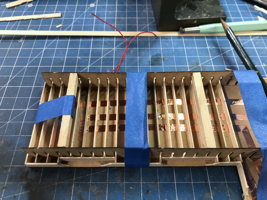
It was time to get working on the balcony, specifically because there's lighting considerations for the porch. Again I'm using the copper foil circuit method and tying this circuit to that of the cupola lighting. The cupola circuit is in parallel to the LED porch lights. Both of these circuits are entering the main house and I'm going to fish the wires down the chimney chase. There is a clear channel the entire length of the chimney chaase. So if anyone is so inclined to stare through the windows and try and find how the wiring is getting below the layout, good luck. You won't see any wires.

I'm using 1X12s for balcony joists. These needed to be relieved around the window and main door openings.

You can see the two SMLEDs that will illuminate the porch. I'll probably attenuate them with some paint so they won't be so glaring.
I'm using a neat laser-cut Joist Jig from Rusty Stumps to lay in the balcony joists. I glued some spacers so the two jigs would keep their orientation. I rarely get the opportunity to use them, but when I do, they're very helpful. I'm also using that length stop add-on to my Chopper II to cut all the joists. The copper foil has a little thickness so I'm cutting some shallow relief cuts on the joists so the rest of the wood lies flush with the surface.
Notice: when I use separate pieces of copper foil to add or change a circuit, I follow up with solder to ensure that those joints are electrically conductive. Notice also the CL2 driver that feeds the SMLED circuit. The other circuit is that incandescent bulb and will just get 12VDC. Those grain-of-wheat bulbs actually work at a higher voltage so it will burn for a long time.

Just completed on the Machine are two Chippendale love seats that I may put facing each other in the living room instead of the longer single sofa. The living room space is narrow so this may or may not work. I'll clean these up tomorrow.
Attachments
Images (10)


Great looking items; every one! The joist jig is nice!!
I see a used furniture warehouse as the next project, with a removable roof to observe Sam, the used furniture sales man, peddling his "cut rate deals".
Myles,
You have taken things to a new level.
I keep doing that don't I. At some point that has to stop. Each project over the last 6 years has advanced the state of the art. There will come a time when I start to repeat myself. Hasn't happened yet, but I can feel it coming.
I had strange print failures with the picture frames. They kept printing as solid blocks of resin with no bevel framing. I thought it was the printer's fault. Nope! It's an aberration in the slicer. Here's the sequence from the slice animation.
When laid on the build plate the part looks exactly as it should: thick flat backing and the shaped framing. The crown molding profiles on Profile Builder 3 create some convincing picture frames.
But as the slice builds, it fills in the entire space between the frames with solid layers, almost to the very top. You can see this looking at how high up the side edge is with the solid filler.
At the very end, the slicer starts building the raised frame, but it's way too late. I don't know what's driving this. The same thing happened to the china cabinet front. What's even more curious, the slice animation now shows the insides open as it was at the start. It's like those layers were never there. But they are! And the printer prints them forming a big flat block of resin that ended up in the trash.
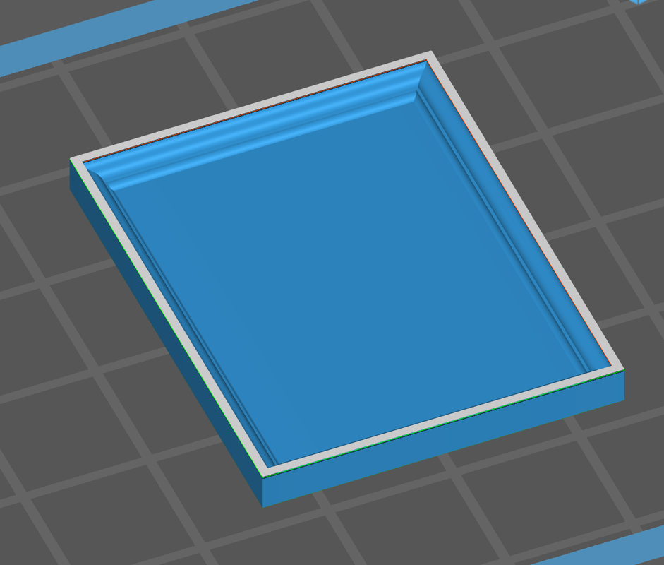
I had to reset all the picture frames on an angle and used supports just on the back so they won't mar the delicate frame designs.
I also had to trash the two love seats I printed. They printed perfectly! But when I dropped them into the living room to see how they'd fit facing one another in the middle of the room, they were HUGE! What??? It turns out that I forgot to scale them. After doing the comparison of sizes in SketchUp, I had to reduce the print size 54% to make them O'scale 1:48. They were probably 1:25 model car scale. They're now in new files waiting to be printed. Resin's not cheap and I hate to waste it, especially when it was just carelessness on my part.
I got all the joists fitted for the wide part of the balcony. I realize I need another SMLED over the front door. Three in series don't seem to be bright enough, but really bright isn't what I'm looking for here, so I may just insert another one in the circuit and see how it looks. They're not glued down yet so adding that other LED is not a problem.
This shot shows the relief cuts I made in all the joists. Don't know if it was worth the effort, but this way nothing is pressing on the somewhat delicate copper foil.
I've set up to produce some coffee tables, but with the success of the dining table and the Baker server, I'm going to reproduce our Henkel-Harris oval Federalist-style coffee table. I took actual meausurements and pictures and will draw it up.
That's a strange nuance on your picture frame drawing. It's always something.
I wonder if anyone at Rusty Stumps ever imagines someone would be building joists over foil LED lighting traces. You are right that foil is so thin, I think it is worth your effort to recess the joists some over the foil.
@Trainman2001 posted:This shot shows the relief cuts I made in all the joists. Don't know if it was worth the effort, but this way nothing is pressing on the somewhat delicate copper foil.
Hmmm... In this particular house, perhaps you should have used knob-and-tube. ![]()
Pete is absolutely right!!
I had to replace one run of live knob and tube in Dad's house last year before we sold it. I wanted to make sure all the knob and tube I saw in the basement was abandoned in place. I discovered one run of knob and tube wire was still hot!! It fed the two lights and two outlets in the sun porch, so I rewired it. Grandpa plumbed the house and got a friend to do the initial wiring way back when in the 1888 house. Then he and dad rewired back in the early '50s. I don't know how they missed that one.
My grandmother's house had the remnants of spool and tube also, but it was rewired to more modern standards. And this House is using DC so in a sense it's like spool and tube, but that's as far as it's going to go.
While I don't work in the shop on the weekends, I do a lot of stuff. It's when I do most of my computer design work. I got the Henkel-Harris coffee table drawn and it just came off the machine a few minutes ago. It's in the hardening cabinet and the pedestals are beautiful. I also designed a grandfather clock based on a nice two-view drawing I found on Google. I also found a nice clock face that will be inserted in the space that I custom-fitted for it. I finished all the joists for the balcony and found that my idea to run the wires down the inside of the fireplace chase won't work. There's a chunk of 1/4" styrene blocking the path down to the bottom. Plan B will be to build an external chase to run the leads on the outside of the building. I reprinted the oversized love seats and attempted to do another picture frame. The frame still seems to have a problem. And I dropped the main exterior door and basically destroyed it. No harm no foul. It didn't fit the laser cut space correctly and really needed to be redone. I re-drew it to properly fit the space and split the door as I did with the interior doors so both sides would have nice clean details especially around the door knobs and dead bolt.
I added the extra SMLED and tested the circuit and with three they were very dim. That wasn't right! Three of these only drop around 9 VDC and I'm using a 12VDC 30Watt LED power supply. I tested each light individually and lo and behold the middle LED was dim. There was resistance there. I re-heated the solder joints on both sides in case there was a faulty joint. There was! With that fixed all three lights were fully bright.

I'm spending a lot of time looking at all the sub-assemblies to see what's missing. I found that the rear wall of the lower turret room was showing clapboard. It should not. I cased this is to add thickness to the wall and provide a surface for some molding.

Here's what the boxed in section looks like from above.

Here's the broken front door. The new one will be better in many respects. The beauty of having the Machine sitting in the shop is if something breaks you just pull out the file and make it again. Additive manufacturing is definitely a game changer. At least it sure has changed my game. The door's printing now and it'a six+ hour job, so I'll be getting it tomorrow.

Now onto the new designs.
The coffee table printed beautifully just like I did with the dining table. The Federalist-style pedestal has for legs that are splayed at an angle.

The print is again two-parts, table top printed flat on the plate face side down. The pedestal is printed also on the plate on it's rectangular pad. I made three sets in case I break anything or if something doesn't print well. Of course all three printed perfectly.
The grandfather clock is being printed in four parts: Base, Main Body, Head and Pediment. The base is printing on an angle with supports since it has some reverse curves that wouldn't print if I did it flat. The body is just sitting on its back flat on the plate. The head is also flat on its back. The pediment is directly on the plate, but drew in some supports for the scroll at the top which I remove after printing.
This is the drawing I found on Google.

This is my drawing as it appears on SketchUp. I beefed up some parts. I added more meat on the base and the finials. The original art's finials wouldn't work at 1:48. This image shows one face that I found.

Here's the face that I settled on. The above face had no hands. This one does. Plus the shiny metal wouldn't print as nicely. This was the drawing that I produced to make the decals. I also printed the Henkel-Harris table top and the face on photo paper. The actual face is a bit smaller than the image on your screen. I always print a lot of them. It kills a piece of 5 X 7 decal paper, I might as well make some provisionals.

It's going to be a lovely model. So I still have a few printing days this week to finish up all the furniture. I need to install all the furnishings before putting the building together. With the wiring complication, the floors won't be easily removable.
Attachments
Images (8)


The grandfather clock will be a great addition!!
The clock is printing right now. I'm anxious to see if all the parts print accurately.
Mixed bag of work today. The love seats printed and will work now that they're in the right scale. I printed the Henkel-Harris coffee table and it's exceptional. The Tenacious/Elegoo ABS-Like blend is producing pretty strong prints. I successfully reprinted the main entry door frame and this time it fits as it should. I also printed another round of picture frames with a different slicer arrangement. Unfortunately, the gremlins are still there and only one came out with the frame fully resolved. The other three had a flat area obscuring the top frame detail. I thnk there's a bug in the slicer and I'm going to find out why. Lastly, I started creating the interior wall detail for the main outer building walls. It's time consuming, tedious, and frankly, I'm not sure it's worth it. It will only be viewed obliquely from the outer windows. In fact, I'm not sure you'll see any of the interior walls that are not actually facing the windows. The jury's still out.
First the love seats. Here's a top view showing how they'll sit in the living room.

This is the coffee table.

Here's how the bottom looks. I held the pedestal to the table top with Bondic. The UV curing light shines through the resin to harden it underneath. This only works for the UV resin since it's partially transparent to UV 405nm.

And just for fun, here's what 1:48 looks like on 1:1. I will apply an image of that inlaid tabletop to the model so it will look just like its big brother.

The front door fit so tightly that I needed to relieve the door opening and shave some off the resin part. But it's the way I like it.

And this shows how it's fitting the opening. After these images, I glued the two halves of the door together, sanded it for fit into the door opening and then glued it in the open position with Bondic.

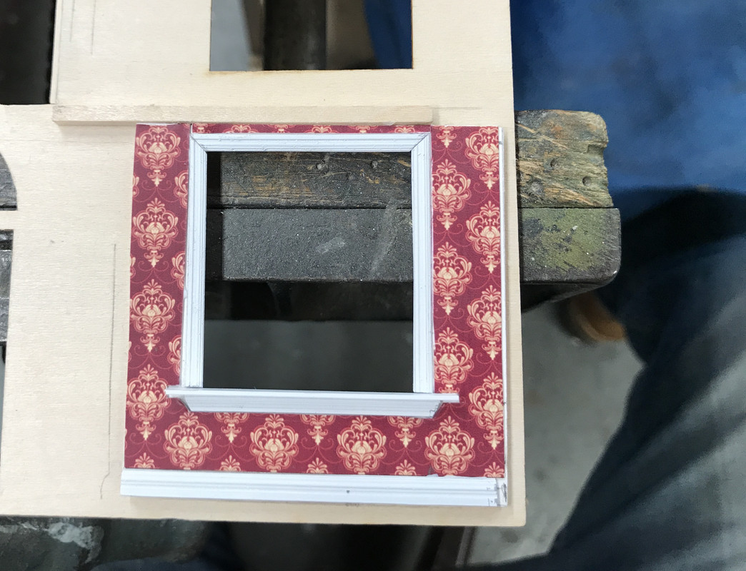
While working on fitting the door I realized that I needed to address the main wall insides. I started with one window and saw what I could do. The resin windows frames protrude into the room by about 0.080". I wanted to pack this out so the wall would be flush with the window. It turns out that a sandwich of one piece of 0.017" thin ply and two layers of Bristol Board made the wall flush with the window protrusion.

I glued the new wall in place and started adding the trim molding using the undersized baseboard left over from before. I then fabbed a window sill out of some 0.030 X .156" styrene strip, and finished it off with some more trim on the bottom. Looks spiffy, but was a ton of work and you won't be able to view it unless the front wall is removable.
Viewed with the wall in place and it looks okay.
I then added baseboard and wall paper to finish it off.
I made a mistake with this wall. I had the wall upside down when I scribed the partition wall position. I was off by about a 1/4" which I can add. But this begs the question. "Does this effort amount to anything of value?" It took a long time and a lot of fussing to do this little bit and there will be about another 8 windows where this needs to be done. The work I'm doing with the furnishings and the inside wall decor is substantial, but you will be able to see some of it through the generous windows, but the walls behind the windows are really going to be hard to visualize, if not impossible. I need feedback.
Attachments
Images (10)


Myles, everything is looking fantastic! I'm looking forward to the clock too! My opinion is if the only way you will see something is if you take the wall out, then it isn't worth the effort. You have enough other models to make for your layout, plus your other modeling interests. On the other hand, if you are going to have it at the edge of the layout and make it easy access to take the wall out to show someone the insides, then maybe you do want to complete the walls in question.
Looks great. The unseen walls are up to you. If it brings you pleasure to know the room is "complete", than go for it. I saw a tv show where someone made a cake of St Patrick's Cathedral with a detailed interior. He used a mini camera on a stick to show off the interior. If completing and moving on is more important then it becomes a waste of valuable time.
Thanks Mark and Pat! After further analysis (you'll see later on) I probably will finish the interior walls. You can see them!
Another multi-tasking work day... 3D printing, airbrushing, window building, interior detailing, and conferring with my darling wife when stuff kept coming up on the 24/7 news shows.
I built the 4-part grandfather clock and wasn't satisfied with the results. Too many details were lost in the cleanup and some added edges due to the residual from the pre-coat layer that forms part of prints that are directly on the plate. I then quickly redesigned the clock. I needed to make two changes to ensure that the parts printed with fidelity. The pediment had to have some supports added in the drawing. The slicer won't allow you to put specific supports in one place with the same accuracy. I also needed to change how the base profile was built so it had plenty of support and still showed the details.
Here are the added supports to help the finials print. As you'll see, the only finial that was at all successful was the center one. While the others printed they were simply too delicate to hold up. I printed the clocks six-up on the plate. I really needed all six to get a good one. In actuality these supports are really tiny and were easy to remove with a #11 blade. I attempted to use the Dremel with the diamond burrs, but the vibration alone was enough to break them off. This was the orientaton on the plate so these details would suddenly appear in parallel to the build surface and this often is not very successful. Furthermore, you can see that the bowl of the finial would start printing attached to nothing... i.e., an island. Islands don't work in a resin printer and simply float away when the plate rises to begin the next layer. The diagonal supports would grow and catch the newly forming islands. It worked.
\
The base change involved making the front profile full-depth and then making the side details shallow with a solid backing. This enabled both to form while laying flat.

The result was very pleasing seeing all six clocks reasonably well formed. If you look closer, however, you'll see that even on the plate, some of the tiny finials didn't form or were destroyed just by brushing on the alcohol cleaning wash.

After separating them, ultrasonic cleaning and post-curing here are the passel of clocks. You can see that only a few have all three finials.

I tried to salvage side finials and Bondic them on to make one good one, but I couldn't even remove one without it being destroyed. So I made one really nice clock without the side finials and it looks great. If the model was 30% bigger the finials would have enough mass to maybe hold together. They're so small I couldn't even machine real ones out of brass. You'd need a true watchmaker's or swiss-type lathe to machine little pieces of jewelry like this.
Vallejo Acrylic Paints had a color in their Air series called "Mahogany" and it was the perfect color for all of this period furniture I'm creating. Vallejo flashes off pretty quickly, but it needs at least 24 hours to fully cure. Otherwise, it's kind of sticky and you really shouldn't handle it. You can see the clock in the lower right. The big table tops are not fully painted since they're receiving actual top photo images.

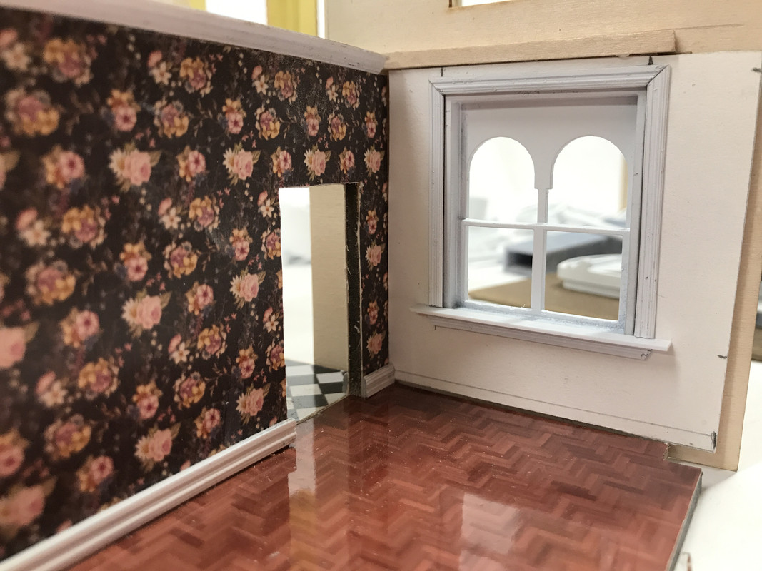
I printed another pile of smaller cross-section base boards if I'm continuing with covering those window walls. I did a photo test to get an idea of how much you could actually see through the windows. And yes! You can actually see those attached walls so I'm going to continue with the wall covering process. The windows are pretty big and do let you view the interior.

While I was trying the exterior wall for the above picture, I discovered this.

When I did the "field mod" by adding that back wall to the dining room (to better display some furniture), I neglected to see that the wall was smack dab in the middle of a window. DOH! That wouldn't happen in a real house since you'd be in the room looking at that window. I will have to change this. The 2nd floor's partitions sit just to the rear of the fireplace and just touch the window opening. I knew what I was doing there. I didn't in this case. Field mods always get me in trouble.
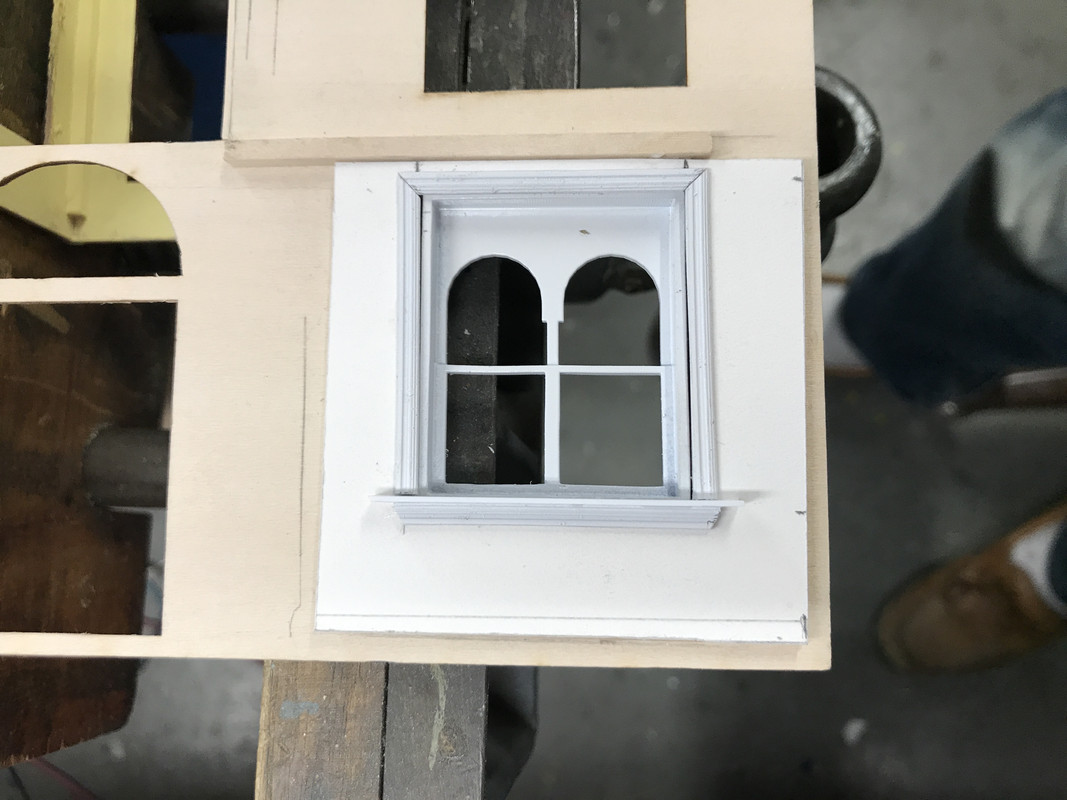
I stopped work on this part because, in addition to painting the furniture, I airbrushed the new front door assembly AND the laser-cut Cupola windows. With my ADD attention now looking at the cupola windows I decided to see how they fit and they weren't great. I believe the cause is due to the inherent resolution inaccuracy with FDM machines. They have inbuilt difficulty in forming tight right-angle corners. If the cupola was resin printed I believe the tolerance would have been ridiculously close. As it is, there is a 1/32" gap on the window tops.

I had drawn window stops into the cupola design, but they only FDM printed on one side of the opening AND they didn't really have a lot of definition. I added my own stops. I used 0.060" sq. styrene held with med CA.

I had to trim the laser-cut window just a tad in height (about 1/64" or less) so they wouldn't be deformed. I then built one full set. I was surprised that the acetate glazing is a little undersized in width. I designed these pieces so it's my problem. It's never the laser cutter. It's always me.
I really needed to get these windows figured out since I can't finish painting the cupola until I knew how the window would interact the space. I'm still in a quandry about how to deal with the strand lines on the cupola. It may not be a problem based on the viewing distance. I'm spoiled. The resin printer produces such amazing surface smoothness especially when parallel to the liquid surface. I may put some flexible trim to encase the window and close all those gaps. The strand lines are especially noticeable in the arches.

Whew! That was a busy day. Tomorrow I have my semi-annual Dr. checkup. In this case it's an annual since it was Covid-delayed. I'm 75, have the usual controlled, pre-existing conditions that almost everyone of my age has; high blood pressure and elevated cholesterol, both of which have been well controlled for 30 years. Thank you modern medicine. I also have Afib which is surprisingly easy to live with. That too is managed. So all in all, life is good. On Friday, I'm escorting my daughter to pick up their new Tesla Y in Cincinnati. They will become a 2-Tesla family. Needless to say, they're really happy with electric cars.
Attachments
Images (10)


Yes they are big windows, so definitely all those walls need finished!! The clocks will be great once you get the tops formed right. I hope you come home from the doctor with a clean bill of health!!
Two Teslas! ![]() I have only seen a Tesla here twice, one passed me on the road, and the other was in a parking lot.
I have only seen a Tesla here twice, one passed me on the road, and the other was in a parking lot.
There are lots and lots of Teslas in Louisville, mostly model 3s. The 3 is one of, if not the highest selling auto in the USA. It is in CA. I think I mentioned the Musk innovation to die cast the entire rear half of the monocoque in the new Tesla Y. It reduced 270 sheet metal parts with 700 welds to 2 parts with some nuts and bolts. And it comes off the machine in 2.5 minutes. Game changer! They have now retrofitted this new manufacturing innovation to the Model 3. They're working to do the same thing for the front half. He wanted his engineers to think about building the car like a model die cast car is constructed. They thought he was nuts and then they did it. Musk has his detractors, but I'm not one of them. He's my kind of innovator. They had to invent their own $40m die cast machine. And they had to develop a custom aluminum alloy that was strong enough without the heat treating that would have set up stresses in the casting. He's doing the same with the batteries and they have the most sophisticated charging software in the world. It's why they're driving the industry. And then there's GM's 1,000 hp, 0-60 in 3 second Hummer pickup truck. It's going to be a paradigm shifting vehicle. My daughter's Tesla was flawless. My son's eTron Audi has had some software glitches. Unlike the Japanese and Koreans, Germans ain't so hot at systems integration. My son didn't like the all digital flat dash in the Tesla. He wanted something more conventional. I think he made a mistake. His miles per charge have been lower than advertised. Like I said, Tesla has the best power management in the world. I want a Tesla, but can't afford one. And they're expensive on the used market also.
I saw a video showing a lot of the process in production of the Tesla! Is is definitely innovative. Musk is definitely doing a lot of good things. I agree they are too expensive for us. $16,000 for a 3 year old Ford Escape was the best we could do for my wife. I still drive the ‘04 Hyundai. I looked up the Hummer EV after seeing the commercial a few times! Wow the price tag is huge also. However, that is usually the way with new technology, and the price will come down in time. We are far enough away from Pittsburgh that we don’t see that much traffic here, and I haven’t traveled out of the county all year.
Add Reply
Sign In To Reply
