It warms my heart when my faithful followers worry when I'm off the air for a while. I warned you that I'm building the tank and that's exactly what I'm doing. It's without a doubt, the most complex plastic kit I've ever built and my kit count since 1954 numbers in the hundreds. Ryefield Models has made separated parts of almost anything. The engine alone had 54 and the transmission has 48. I have to make sure I'm not hungry or my shaky hands make building really difficult.

Here are some images showing progress.

The photo-etched 3-piece brush guard was a bust so I scratch-built one out of styrene.

M4A3 Horn Brush Guard Complete 1

The late Shermans had a very well armored and hidden exhaust outlet. BTW: the tow hooks actually articulate.

M4A3 Tail Details

This was the fabulous Ford GAA V8. It was a dual overhead cam, four-valve, hemi, with aircraft style twin magnetos and twin plugs per cylinder. Everything was gear driven. It was a 500hp monster which was never taxed in driving Shermans.

M4A3 Engine Painted 2

The ignition conduits are scratch-built phos-bronze. I didn't like the kit plastic ones.

M4A3 Engine Painted 3

All the operators controls are there. Some of this got covered with a floor panel. The broken clutch linkage happened before I got it off the sprue. I didn't even know it broke until I found the broken piece on the floor when looking for something else.

M4A3 Driving Controls

The installed and complete engine bay. Twin radiator fans were driven by two small drive shafts coming out of the front gear box at right angles driving two other gear boxes which in turn had pulleys and fan belts to run the fans. Lots of redundancy. There were 6 fire suppression nozzles in the engine bay also which are on the model.

M4A3 Radiators Done

The 48 piece transmission assembly. The box on top is part of the ventilation system. The blower mounted on the ceiling and is right above this. The round assembly sticking out the back is the generator driven by the main drive shaft. Strange that it was installing the fighting compartment and not the engine bay. Gear shift is the lever in the view.

M4A3 Trans Complete 2

The rear upper hull has a lot of separately applied handles etc. The fender supports were a nice detail (11 pieces on each side). The luggage rack had 2-part PE pieces for the supports. They didn't work so I substituted some PE fret brass.

M4A3 Luggage Rack

The driver compartment ceiling has periscopes hatch counterbalance system and the ventilation blower.

M4A3 Vent Install

I'm trying to devise a way to display all of this so you can see the insides of all the various subassemblies. That includes the undersides of the upper hull and the fantastic detail that's all around the turret. I'm thinking about taking a mirror, putting a piece of clear acrylic (if there's any left anywhere in the world) on top of that, and then using clear Lucite rods to support the chunks above. This way the mirror will reflect what's underneath without anyone having to touch anything. It's a REALLY delicate model.

So, fellas… that's what I'm doing. Meanwhile, as I noted before, I have all the components needed to build the HOUSE and will be working it when this is project is done. It's moving fairly fast, so I'd say in about a month. We're not going anywhere so I'm in the shop pretty steadily.

Attachments

Images (9)
  • M4A3 Radiators Done
  • M4A3 Trans Complete 2
  • M4A3 Horn Brush Guard Complete 1
  • M4A3 Tail Details
  • M4A3 Engine Painted 2
  • M4A3 Engine Painted 3
  • M4A3 Driving Controls
  • M4A3 Luggage Rack
  • M4A3 Vent Install


The FM looms over the others in the inventory. It was difficult to repair FM engines due to their size, twin crankshafts and inability to easily get to the lower end. The easier to maintain, by far, was EMD where you could pull the entire power pack (Cylinder, head, valves, piston and connecting rod) directly out of the top of the block with a portable crane that bolts directly to the engine. In a couple of hours you could completely restore a bad cylinder.

FM in position


The FM prime mover is an opposed piston (OP) design hence the tall height compared to the competitors' engines designs. They were harder for access to the power assemblies (more time/labor as you have noted) but properly maintained also would run longer between overhauls than the typical EMD from what I've read. 

Above outdoor storage lot scene is excellent except for one detail - the stacks are not covered! Not a problem if stored under a roof but in the open rain/snow can enter the prime mover which is not a good thing. Placing simulated tarps over the stack openings would be a good idea here. Of course if these prime movers are destined for scrap this isn't a problem then but the paint looks too nice to be worn out engines. I believe in your scene here they are spare engines ready to be installed? The average person wouldn't pick up on this particular detail in all fairness.


As an aside 5-gallon buckets are commonly used to cap the stack(s) on EMD switchers when in storage. See below link for an example:

https://www.hebners.net/Amtrak/amtSW1/amt740.jpg


Always enjoy following your projects here including the techniques, issues, mistakes and corrections encountered along the way!

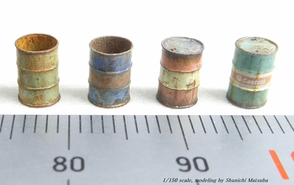
Now I have to figure out how to make scale five gallon buckets. I know just the guy. His name is Sunichi Matsuba. He and I are Facebook Friends. He lives in Northern Japan and works exclusively in 1:150 scale. His work is off the chart and he does it using a binocular research microscope. We have a mutual admiration society going since I find his work spectacular and he finds my inspirational. This is his work: 50 gallon drums in 1:150 next to a metric ruler. 

109290605_3335711219814384_9206630397928678212_o

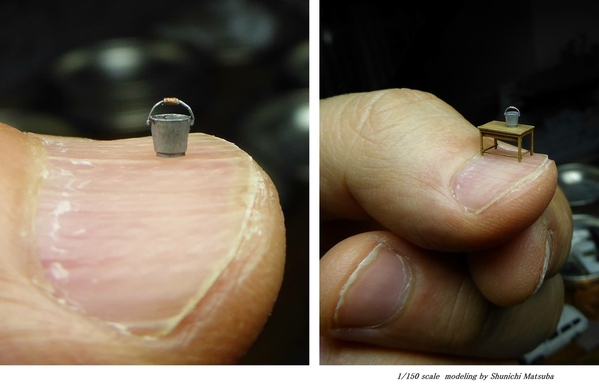
This one drives me crazy. Sunichi could definitely make me some 1:48 five gallon buckets. 

12622067_1082162078502654_2709055489124978757_o

He has many FB friends all over the world of which I am one. That said, it's even more weird than that. We both play Fender Stratocasters, have the same taste in music. We've already determined that if I ever had the opportunity to travel to Japan, I would be his guest. The internet, with all its abuses, is a marvelous tools to shrink time and space, introduce new ideas (both good and bad) and learn about each other. He and I would have never met in any other medium or universe. As it is with all the wonderful people who've been following my stuff here in OGRR for years.

Sunichi's work is not that unusual and follows in a pattern of fabulous Japanese craftsmanship over hundreds of years. Years ago, when I wanted to get into live steam engine building, I found a series of engine articles in Live Steam Magazine penned by another Japanese master, Kozo Hiroka. He specialized in 1:12 scale geared locomotives. He then published books on them. He built the Shay, Heisler and Climax engines. What made his work so remarkable was several things. First, he used no castings. Everything was machined and/or screwed or silver soldered together. Second, he built his own tooling to accomplish many challenges you face when building a working locomotive. And lastly, he did this all in the corner of a tiny Japanese apartment and was married too. Any one of these facts would make his work remarkable, but taking in all three and then seeing what he built was awe inspiring. Whenever I think I'm at the top of my game, I look at these to guys and see how far I have to go.

Attachments

Images (2)
  • 109290605_3335711219814384_9206630397928678212_o
  • 12622067_1082162078502654_2709055489124978757_o

I can relate to the wall at the bottom of the stairs.  We live in a small split entry house that was first built by my wife's grandparents.   My concern especially when I was learning to negotiate the stairs after knee replacement was falling into the stained glass door height window my late father-in-law made that is beside the front door.  If I survived the fall through the window, I may not survive my good wife's initial gut reaction to the demise of the window.    I still cringe occasionally when going down.

Sunichi Matsuba's work is amazing in 150:1 scale!!  My best find on the internet is my cousin in Seattle who I only saw in person once.  That was in 1964.  I also have friends of similar interests and backgrounds I never would have met otherwise.

Catching up a bit on this thread. After the recent hurricane, we lost electricity for a week. Now I have electricity but no cable or internet. Data on my phone is sporadic at best. Probably due to the high demand. Thanks for the update. I'm glad to hear all is well with you. That 1:150 scale pale & table is amazing. Thanks for sharing. 

That must have been awful. Living without lights or refrigeration. Living without the internet is intolerable. How can I buy my crap on Amazon without the internet???

Some news. I'm getting back into designing the coal mine for the mountain. I found out that my entire concept DOES NOT FIT THE SITE. In fact, I really don't think any mine can actually fill that site. I may just put a picnic grove there. There's too much vertical drop, but not enough horizontal spacing. I'll keep you posted. Meanwhile, tank building is still challenging. It's complex and over-engineered. Some parts should have been reduced/redesigned to make it more practical, buildable and/or sustainable. For example: the bogies are sort of articulated, but the moving parts are so fragile that some needed to be fused so it would hold together. I'll keep you posted.

I found out that my entire concept DOES NOT FIT THE SITE. In fact, I really don't think any mine can actually fill that site. I may just put a picnic grove there. There's too much vertical drop, but not enough horizontal spacing. 

How about an abandoned mine?  Maybe a boarded up slope entrance, remnants of a collapsed structure, the ghost of a narrow-gauge track, a forlorn vehicle or two, and however much abandoned, rusting gear that will fit?

Last edited by Avanti

Hey Myles, I'm still playing catch-up with topics. Love the Sherman work, really like the buckets too. My uncle's MF tractor he had he used to have a small coffee can over the stack. Well, he forgot to take it off a few times and it laughed quite a bit. Later on he used the cut bottom half of a plastic soda bottle. He melted a few of them a bit. Ah, the good old days.

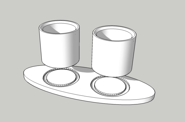
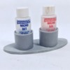
Hey guys, time to check in again so everyone knows I'm still at it. First of all I 3D printed a holder for Microsol and Microset decal setting liquids. I don't know about you, but I never use this stuff up. I spill most of it. Those light, tall, skinny bottles want to be horizontal all the time. I was resorting to clamping the in the woodworker's vise on my modeling bench, but finally decided to design and print a permanent solution. It was a simple SketchUp project consisting of three parts. I explored printing it as a single object, which it could do, but it would have made for more supports. By making the tubes separately, I was able to print them directly on the build plate with no supports at all. The base has some retaining groove to provide gluing surface for the tubes.

MicroScle Bottle Holder

The base printed perfectly, even though I hadn't printed anything for months. I simply ripped off most of the supports by hand only having to using cutters on the stubborn ones.

Work Place Microsol Holder Base

I glued the tubes into the grooves using the same liquid resin from which the objects were created and then put the assembly into the UV cure chamber. It took about 40 minutes to strengthen the object AND penetrate into the joint and harden the resin. The object is now like a homogenous structure. Here it is in use. No more spilled decal solutions. I also had a similar holder made for my CA collection, but had it done at U of L's ADMIST lab since it needed a larger FAM printer.

Work Place Microsol Holder

I no longer have to search for the right stuff and especially the accelerator. All of these bottles, like the Microscale products are tall and skinny and fall over all the time. Not anymore!

3D Print CA Holder

I've been doing some serious workplace mods to stop me from spending hours crawling around on the floor looking for parts that have left the area. I built up walls around the bench and stapled a cloth that I clip to my shirt that forms a great big lap to catch micro parts. AND IT WORKS!

Workshop-Parts Catcher POVWorkshop-Parts Shield Attach

Parts can still leave via the left side, but my airbrushes are in a holder on that side, and, being right-handed, clipped parts usually head off to the right. I just finished this mod last week and it's earned its keep.

Workshop-Parts Shields

And now a few more Sherman status shots just to whet you appetite.

The tracks consisted of 760 individual pieces, many of which had to be very carefully glued to make the track flexible. It took a week to build it. You do it in a fixture of 6 links per section. Each track consisted of 10 sections. The first section took over an hour and drove me nuts, but by the end I was completing a section in 10 minutes. Learning curve! Nothing about this kit was easy. And I mean NOTHING! Track: first coat: Tamiya Dark Iron. Second coat: AK Interactive Real Metal wax-based metallic paste. Third Coat: weathering powder for grime and rust. This is a lightly used late war tank and is on display so it's not beat up or caked with mud. Builder's choice.

M4A3 Track Install 2

The hull top and the turret will not be glued on. There's just too much going on inside to hide it.

M4A3 Track Installed

The hull interior is complete. It's amazing.

M4A3 Hull Done Right

The underfloor, liquid enclosed ammo magazine was a feature of this late model Sherman.

M4A3 Hull Done Left

The turret interior didn't disappoint either. The gun recoils and elevates. The hatches open, although I had to scratch-build the hinge pins on the commander's hatch to make it do so. Another feature of the M4A3 76W HVSS was the truncated turret basket floor. This was severely cut away to permit access to the aforementioned under floor magazine. The gun alone had about 50 parts. Those thin pipe supports for the recoil guard were very fragile. I ended up breaking them and replacing them with Phos-bronze. Much stronger.

I used Bare Metal Foil for the equilibrator and guns slides. The gun barrel goes in later and will have a spring to allow the recoil to operate realistically.

M4A3 Gun Paint

M4A3 Gun InstalledM4A3 Turret Basket Installed

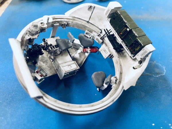
Those two red buttons on the floor are the firing buttons. The one of the right is for the main gun and the left is the coaxial 30 cal. machine gun. The black pistol grip is the gunner's power traverse control. The open box upon which the gunner sits is the ready round ammo box. Since you can only get to the underfloor magazine when the turret is in a specific position, the loader would first go for these rounds.

M4A3 Turret Basket Detailed

Today I was working on the turret top details. I'm pretty far along with only a few pages left of the 62-page instructions. I've actually masked the glazing on the periscopes so when they're painted the optics will be clear. I know… nuts. The mold detail and accuracy of the model has been off the charts. They made multi-part assemblies of almost everything. Sometimes it's a bit overboard, but you can't fault them for trying.

M4A3 Turret Top Detail

The tank will be done in about another week so you can expect work to begin on the Hopper House soon after that. After all, we're not going anywhere. So, as you see, I have been busy.

Stay safe! Wear your mask! Be well.


Attachments

Images (16)
  • MicroScle Bottle Holder
  • Work Place Microsol Holder Base
  • Work Place Microsol Holder
  • Workshop-Parts Catcher POV
  • Workshop-Parts Shield Attach
  • Workshop-Parts Shields
  • M4A3 Track Install 2
  • M4A3 Track Installed
  • M4A3 Hull Done Right
  • M4A3 Hull Done Left
  • M4A3 Gun Installed
  • M4A3 Turret Basket Installed
  • M4A3 Turret Basket Detailed
  • M4A3 Turret Top Detail
  • M4A3 Gun Paint
  • 3D Print CA Holder
In my attempt to keep my O'gauge fans up to date, I'm declaring the Sherman done. I didn't put enough gloss in a couple of spots so two decals silvered. My attempts to 3D print a special stand to hold the upper hull and turret so far aren't going so hot. I won't give up. But the tank is complete. All 1,900 usable parts for this version has been consumed.
My final analysis: Probably the most challenging out of the box plastic kit I've ever built and I've been building since 1953. Ryefield did a commendable job of locating every detail imaginable, but in doing so over-complicated the model without a commensurate improvement in appearance. The treads were insane, and many of the parts were so minuscule that you ran the risk of them disappearing in the attempting to clean off any sprue remnants. There were 17 parts just on the Browning 50 cal. There were 7 parts in the traverse control stand. But regardless, I accepted the challenge and created a pretty good model both inside and out. Even the tow cable had a challenge. The clamps that are supposed to hold the ends to the tank consisted of a tiny plastic base, a tiny piece of photo-etch that needed shaping and a microscopic wing nut. Serious overkill.
So when fellas tell you to "Not touch the models" when you go to a model contest, in this case, they're not kidding around. This puppy is really delicate!
M4A3 Cable End
So… next week construction will begin on the House by the Railroad. So stayed tuned.
M4A3 Done 3M4A3 Done 1M4A3 Final 2M4A3 Final 1M4A3 Done 4M4A3 Done 2
 

Attachments

Images (7)
  • M4A3 Done 3
  • M4A3 Done 1
  • M4A3 Final 2
  • M4A3 Final 1
  • M4A3 Done 4
  • M4A3 Done 2
  • M4A3 Cable End

Look no more. Work on the House commenced today. Started work by finding my errors. Unfortunately, no matter how hard I try to match up all the walls and floors stuff slips through the cracks. In today's instance, I found two. There will be more. These are just the two I found today. The first was one side wall was 1/16" too narrow. I fixed it by adding a piece of strip stock. It will be covered by the corner molding.


HBTRR Right Wall Stretch

The second error was the 2nd floor stair well opening was about 3/16" to much reward. I found this out by fitting the first floor partition walls, the stairs and the second floor plates (2). I measured the amount to open up and used a good old coping saw to remove the excess. I will have to add back this amount on the other side of the opening. No problem. Notice that the opening is two-level. This is so the railing can drop into the space and be flush with the floor. It's actually by design.

HBTRR Stair Well Fix

The last thing I did was add the 2nd floor stops. I put the partitions up against the wall and marked the location of their tops. This was scribed around the perimeter walls and then 1/8" stock is glued to the line. I didn't bring these out to the extremis, instead I stopped short so there's clearance if I add any corner bracing. After you build enough of these you start to plan ahead for these clearances. Oh… And I had to keep track of making sure the clapboard (on the outside of these pieces) was facing downwards when I scribed the floor stop line. I've screwed that up before too. The big second floor windows are quite close to the floor, but I was restricted in overall height due to the 6" sizing of the clapboard sheeting. I didn't want to have any horizontal seams.

HBRTT 2 Floor Stops

This is the part of the build that goes quickly so I should have walls erected within the next day or so. I have to print out my plans to sort out which interior wall goes where.

Attachments

Images (3)
  • HBTRR Right Wall Stretch
  • HBTRR Stair Well Fix
  • HBRTT 2 Floor Stops

I know, I know. My greatest skill is recovering from screwups. I don't let them get me down. It's just another problem to solve. Today, I found that the second floor plates (2) are about 3/32" narrower than the first floor plate. The 1st floor plate is correct since it has to match the sides in width and be two wall-thicknesses shorter in length. Again, don't exactly understand how this occurs since I place all these shapes in congruence with their mating surfaces to make sure they matched. Obviously I missed some since the laser NEVER LIES!

I decided to attack the fireplace walls first. These needed to be built out and it was easier to do both floors as a single assembly and then cut the floors to wrap around them. I printed out some exposed views of the building and stuck them to my recently erected "Parts Catching Backstop Walls" that surround 1/2 of my work table. While these views don't give measurements, they help me identify the interior wall partitions which can be confusing. I ordered some more Northeastern strip wood for the joists under the balcony, and some password 1/8" angle for the corner trim.

IMG_7606

In the above, which I just took, you can see what I'm about to describe in more detail; the fireplace build.

I had a choice to install the fireplaces after all the walls were erected, or now. I chose now. That said, it does add a complication; the 2nd floor plate has to slide down past them. I have two choices about this problem. I can made a notch big enough to clear the hearth, or I can notch the floor just big enough to wrap around the wall bump and split the floor plates so I can insert one at a time. If I made the bigger hole, I can cover the gap with a larger piece of hearth flooring. Often the area in front of the fireplace is not wood like the rest of the floor.

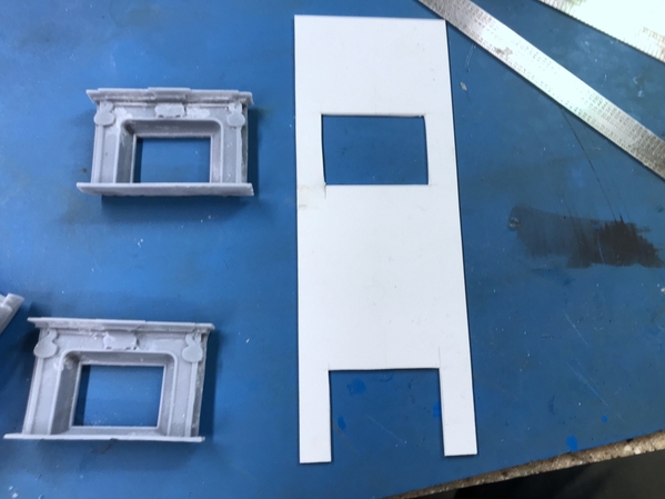
I decided to use styrene for the wall front since I didn't have any ply that would work and chose what I had. I was going to use styrene for the filler pieces to set the wall away from the house wall by a scale foot, but didn't have enough 1/4" square stock and chose to use 1/4" basswood of which I have a lot. I used med CA to glue the wood to the plastic. It's not always great, but it works especially if you rough up the styrene before gluing. There is a boss on the fireplace back that I wanted to drop into the wall. I measured it all up, scribed the opening with a small machinist square and a #11 blade and broke out the pieces. I did this BEFORE I glued on the thick stuff pieces. 

HBTRR Fireplace Wall Openings

I dropped the fireplaces into the holes and measured how much space was left behind them to the building wall. I wanted to build a firebox to give the assembly some substance. 0.100" X 0.60" styrene strip fill the space nicely. I measured and cut pieces. The styrene to resin was again with med CA and then I used solvent cement to secure the corners to each other.

HBTRR Fireplace thickstuff

When putting pressure on the wall to glue in the fireplaces, I noticed it was bowing in the middle. So I added some 1/4" sq. styrene to beef it up. 

HBTRR Fireboxes

Before gluing the fireplace wall the building, I painted the firebox and the back wall flat black so it would give the allusion of being large and sooty.

HBTRR Fireplace Hearth

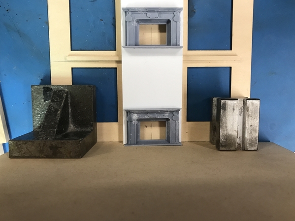
I used a big machinist angle block to hold the wall perpendicular, and then pushed the floor plate up to the wall and clamped it to the work bench. I then applied Aleen's Tacky Glue to the thick stuff and clamped it to the wall. After a couple of minutes, I took it off the block and put a 2X4 across with weight on top so the glue would cure. This freed up the block so I could glue the other fireplace wall in place. You're looking straight down.

HBTRR Gluing Fireplace Wall

It was time to glue the walls together. But before I did this I glued the double 2nd floor plate together. This gives a close to scale inner-floor thickness. I used Titebond and clamped in the woodworkers vise. I also added 3/32 material to pack out the back side of the stairwell hole to compensate for the material I cut away yesterday on the front edge.

IMG_7603

Before glue up I added some small corner blocks to provide some strategic support without having them completely visible in the rooms' corners. Notice too in this image that instead of notching the fireplace wall to clear the floor stops, I simply removed a section of the stops. It was an easier mod. Notice also that instead of adding material to the short floor, I added it to the base of this wall, like a baseboard. It was enough to bring the walls even with each other and the floor.

HBTRR Corner Braces

I glued the first corner using a combination of corner clamps and Quicki Clamps. I first used Aleen's and the went back with Med CA. 

HBTRR Gluing the first Wall

I'm faced with another dilemma. It would be nice to paint the fireplaces now, before they're surrounded by four walls. I may glue up the walls as two corners, paint the fireplaces and mask them so they don't get damaged, and then bring the opposing corners together. I did the same routine with the engine house. This is easier since it's not 20 pounds and 40" long. I also need to keep all the floors removable since I don't have furnishing for this building yet, but don't want to hold up construction because of it. If the floors are removable then furnishings are not on the critical path.

Attachments

Images (9)
  • IMG_7606
  • HBTRR Fireplace Wall Openings
  • HBTRR Fireplace thickstuff
  • HBTRR Fireboxes
  • HBTRR Fireplace Hearth
  • HBTRR Gluing Fireplace Wall
  • IMG_7603
  • HBTRR Corner Braces
  • HBTRR Gluing the first Wall

"I know, I know. My greatest skill is recovering from screwups."

Myles, I think that is a great skill indeed!  Sometimes, once I see I have made a mistake, I just throw it all away and start over.    Very costly in your case here with custom laser parts, though if I recall correctly, you had Andre cut a second time with the correct measurements.  Today's work was a well thought out process.  I can see the choice of doing it this way first or leaving the fireplaces until later.  You really provide some great thoughts to tuck away for the future.

Thanks! Seems that way now, but the devil's in the details. Still have a lot of decisions and actions about the lighting. I bought some fiber optic filament from MicroMark that I've been itching to try. I'm thinking about how to make an O'scale chandelier to light the dining room and foyer. This may be impossible, but it's worth thinking about. I'm also debating when to glaze and install the windows. In the past, I've held off window installation as long as I can. In this case, I may put them in early and mask them to keep them clean. The main reason for doing it now is to be able to build window framing on the inside. Once the walls are all erected, window trim becomes much more difficult. I've said this before, the biggest difference in scratch-building your own designs and a kit is the lack of instructions. You have to invent them as you go along and sometimes you paint yourself into a corner.

Re: the chandelier. If I use the fiber filament I can put a single strand inside a small piece of tubing and bend it into the curve seen on many chandeliers. To express the light at the end I'm wondering if a "bulb" created with a drop of clear Bondic UV resin would work. I'm going to do an experiment to see if the light emits properly from this creation. Then I would bring the curved tubes together and bring the bundle to a place where the LED can be installed. I think the second or third floor will be dedicated to the lighting system. The LEDs could even be in the basement. The building will be 1" elevated on a "Stone" foundation.

I report more later today when I finish today's work session.

Re: the chandelier. If I use the fiber filament I can put a single strand inside a small piece of tubing and bend it into the curve seen on many chandeliers. To express the light at the end I'm wondering if a "bulb" created with a drop of clear Bondic UV resin would work.

Sounds like a job for the 3-D printer. You could print little channels (or maybe even tubes) for the fiber. If you use clear resin, you could print the little "bulbs", too. I would print it upside down flat against the build plate.

Or, conceivably, you could make light pipes out of clear resin, and skip the fiber. I have been wondering if that would work. You could paint everything but the bulbs. I do understand your wish to try the fiber, though. 

Last edited by Avanti

Myles, I'm great at painting myself into corners!    I am not a chess player, but it seems to me a project of this scope requires you to think many steps ahead as a chess player would.  I know when I was working, no matter how much experience, when it came to one-off projects, I often had to tear it apart physically or in the design because I had reached the end of the tunnel, and there was no light, just a rock wall!  

I missed Avanit's comment about the chandelier. I thought about that too. I don't know about the optical properties of the clear resins. I have some that's translucent which would scatter all the light. I will have to play around with this. Sounds like a project all by itself.

Today was interesting—in the ancient Chinese meaning—with repairs and repairs to the repairs. Part of my problem is I should have etched the part's description on the pieces. My removal of stock from the 2nd floor plate was unnecessary and I had to add it back. I had the plate oriented incorrectly. It wasn't until I got the foyer walls constructed and the stairs in place that I could be sure of just how big and where the stairwell opening should be. It was very difficult for me to get it right in SketchUp, so I'm not at all surprised that I was struggling with this aspect of the build. There will be other things that will come up around the cornices, the tower floors, etc., so it's not going to get easier. I was going to cut off excess height of the 2nd floor hall walls, only to find that they were the first floor's. The real 2nd floor needed a little trimming, but nothing drastic. And so it went. 

I notched the 2nd floor corners to clear the 1/4 square reinforcement blocks. I then glued up the front and left side walls as I did for the opposite sides yesterday.

HBTRR Corners Glued

I needed the front wall to be able to place the steps correctly. When I was able to position them correctly I found that my removal of stock yesterday was in error. I had the plate reversed. I used some 1/8" Masonite to create filler pieces. I then filled any gaps with Tamiya filler. The back edge where I added stock is now also wrong and I'll fix that in the next session.

HBTRR Fixig the fixes

I measured and cut the relief to clear the fireplace. As I worked on all this today, it became more clear that even if the floor plate could lift up, it probably won't clear the assembled stairs. I will do what I did with the Woodbourne Gallery and leave the floor plate unglued so I can wire the lighting from the bottom. This whole deal is very tricky.

HBTRR Fireplace Relief

I also found that the bedroom partition walls that key into the hall walls were ending up smack dab in the center of the side windows. I measured where they should actually go and re-notched the wall, and filled the incorrect tab slots. I used the same material to fill the slots. It's nice to have power sanders and scroll saws to do all this work. The MDF Rail Scale used is conveniently 1/8" thick so I can use 1/8" Masonite to fab any missing parts, which you'll see I will use.

HBTRR Repositioning Tab Slots

When I put the hallway pieces against the building wall it was WAY TOO TALL! I marked it and was ready to cut, when I decided to try it on the first floor. Whaddaya know? It fit the first floor. I had them reversed. 

HBTRR Not a Mistake

With all this sorted out, I added some strategic corner reinforcements and glued the first floor foyer walls together. I used by big table belt sander to remove evenly the 1/16" of stock that was still too tall. In the process it grabbed a bit and broke off the door frame which has a very narrow connection to the rest of the wall. I re-glued it and then added 1/16" sq stock on both sides to reinforce. This will make the hallway walls not so pretty… another unforeseen consequence of making field modification. The problem is that the 1/8" tab joints don't provide much gluing area and are a bit unstable.

I added another piece of 1/4" square stock across the foyer face to force the sides into parallelism. It will be at the ceiling. If it's in the way, I take it out.

HBTRR Foyer Glue Up

I fit all this stuff together to figure out how I want to make the entry closet. The stairs project out past the entry into the dining room. I had a piece of foam core as the stair wall, but removed it and made it out of more substantial Masonite. I then found its end point and cut it to that length. I measures the distance from this side wall piece to the stair landing's back width. I cut this out of Masonite and glued it to the side piece. A picture tells this better than words.

HBTRR Entry Closet Build

The 2nd Floor plate needed to move back to align with the rear wall. It was being held off by the newel posts so I cut relief cuts to let it slide back. Rightfully, the newels should have fallen on top of the floor plate, but the math didn't work out right with the stair rises. This was one discrepancy that I knew about during the design phase and figured I'd fix it in the build. The second floor walls are not glued together in this image. Note also that the wall behind the steps is not correct. It needs to be wider and have a door in it. I'll make it out of Masonite. In this picture you can also see that the partition walls just fit beside the fireplace cutouts. That's the new position.

HBTRR Newel Notches

Onward and upward. The job would have been much easier if I didn't have delusions of grandeur in making an elaborate 3 story staircase. But you never advance unless you try new things. And in every project I've done in the last 6 years, there's always been something new. This one has a lot new.


Attachments

Images (8)
  • HBTRR Fixig the fixes
  • HBTRR Fireplace Relief
  • HBTRR Repositioning Tab Slots
  • HBTRR Not a Mistake
  • HBTRR Foyer Glue Up
  • HBTRR Entry Closet Build
  • HBTRR Newel Notches
  • HBTRR Corners Glued
Last edited by Trainman2001

Good progress on the house, Myles. If it was easy you would be bored. I made movie marquee chase lights using fiber optics. There is a limit to how much the strand can bend. That may or may not impact a chandelier build. The light from a fiber optic strand is a pinpoint straight out of the fiber. I passed the end of the fiber over a flame to diffuse the light so it can be seen. Something to consider.

After exercising today, I got in a few good work hours. I got the first floor walls glued to the floor plate. I did this before painting. It was just too much fussing to permit painting. They were slightly out of square, so I glued one wall in squared up to the front edge using both Aleen's and med CA. I then pulled the other wall into square so all the edges matched.

When I went to build up the 2nd floor's walls, I noticed that the walls hung over the floor by about 1/8". I was just about to cut the walls shorter, and then I tried the floor into the building as it stands now, and found that the floor was short in its width by that amount. I added filler pieces with to pieces of strip wood laminated to the edge. I clamped it until it cured.

HBTRR 2nd Floor Filler Clamp

With the addition the floor was perfect.

HBTRR 2nd Floor Filler Piece

With that fixed I was able to fit and glue in the 2nd floor walls… or so I thought. In the above picture, I had placed the floor in upside down. I then transferred it to the workbench without checking and firmly glued down the first wall set. And of course it was all CA'd and shot with accelerator. DOH! I had to use an Xacto knife to start breaking the joint. I got it off without too much damage to either the walls of the floor, sanded the cured glue off the parts and put it on the correct side and did it all over again. Luckily I caught it before gluing in the other side. Silver lining.

I did some final fitting on the stair wall for the closet so it nestled closer to the stains. I added a trim board up the length as a buffer between the stairs and wall. I used the pressure sensitive tape to glue the wood to the resin. I cleaned up the fit when the 2nd to 3rd floor stair nests into the floor plate. There will be a railing protecting folks from falling through that gap. In looking at this image, I realize that I should have made the bedroom wall a little shorter so the hallway was a bit wider. Won't matter. You'd have to view it through the turret windows. I don't think you'll see much. I need one more wall behind the stair with a doorway. Should have been cut, but I probably missed it. If it wasn't in the file I transmitted, it didn't get cut. Wish I had my own laser cutter...

HBTRR 2nd Floor Walls Install

I got the roof plates out and tested their fit. The upper stair rail needed a little help to settle into the floor.  The two railings will mate with some coaxing. It was rewarding to see that the 3rd floor stair well opening was pretty close. These minor adjustments were expected since I never really got the drawings exactly right and was constantly adjusting them.

HBTRR Upper Stair

Then it was time to make the first chandelier test. I cut a piece of fiber and bent it. I cured a drop of UV Resin to form a bulb and then held it up to a warm white LED. The light did illuminate the resin ball although most shot straight out. I may try frost the bulb to see if the light will diffuse. I attempted to form the fiber into a chandelier arm. I used some twist brass wire to do it, but it's certainly not ideal. I could use some brass strip drilled to receive the fiber. I then attempted to put it all together with some shrink tubing, but I didn't have the right combination and gave up. I ordered some more tubing of the correct size and some more LEDs from Jameco Electronics. I suspect, given enough time, this could work. In heating the larger tubing enough to shrink over the smaller, I melted the fiber and the smaller shrink tubing. Actually, there will be more than one fiber in the bundle so my tubing sizes won't be trying to bridge such different diameters. 

HBTRR Chandelier Test 1

Back to the building. Remember when I said there were more questions, like, "What to do about the cornices?" One of the cornices I was talking about is this one. 

HBTRR Cornice Question

When I ordered the parts, I forgot that I redesigned the roof plates to include this cornice. I had him cut the turret walls as solid going from the 2nd to 3rd floor. Whoops!

I had to cut these walls in two parts, one to match up to the roof undersides as shown here, and then remove the roof thickness (a scale foot) from the upper walls. I also realized that I didn't have him cut a back turret wall. I don't have Northeastern Clapboard stock, but I do have some Evergreen Styrene Clapboard that I'll use (multi-media project). The cut pieces came out very good so that problem is solved.

HBTRR Turret Wall Fix Check

I glued some internal corner posts to these walls in preparation of gluing them together tomorrow.

HBTRR Turret Walls Corners

I still have to decide how to connect the balcony (porch roof) to the building since clapboard gives a limited gluing surface. I wish I had some more since I could turn it upside down and key the sawtooth into each other making a solid surface. I may just order a sheet of it to have.

I took a picture through the front door of the staircase, just for fun. I think I'm going to get rid of that corner block in the far corner. It bothers me. I had another thought. This house could be a serious renovation and have recessed lighting as is done with lots of old houses. That is, if the chandelier deal is a bust. It will look good with door casings and doors, baseboards, wood flooring etc. Before the stairs are glued in all the stair stuff has to be painted.

HBTRR Main Stair Interior View


Attachments

Images (9)
  • HBTRR 2nd Floor Filler Clamp
  • HBTRR 2nd Floor Filler Piece
  • HBTRR 2nd Floor Walls Install
  • HBTRR Upper Stair
  • HBTRR Chandelier Test 1
  • HBTRR Cornice Question
  • HBTRR Turret Wall Fix Check
  • HBTRR Turret Walls Corners
  • HBTRR Main Stair Interior View

Another busy day...

Most of the work was on the turret. I discovered several problems that needed to be solved. The turret slots in the wall were about one to two wall thicknesses to wide. I hate slots! It caused me to cut the cross-brace I had just glued in to stabilize the back end and add about 1/6" filler. The walls are slightly out of square, but luckily (for me) it's nestled under the turret cornice and won't be too visible. My strip wood arrived from Northeastern in perfect timing so I was able to start adding trim as I went along. I epoxied the cupola onto the turret roof and then filled some gaps. I also glued the main roof pieces together. All in all, a pretty busy day. So let's look a little closer.

The FDM 3D printed cupola has some cross-bracing on the bottom that needed relief in the turret cornice piece. I used the scroll saw and had to drill a pilot hole, and disconnect the blade to do the internal cutting. I don't do this very often with that machine. I would usually use a jeweler's of coping saw. As it was, the mechanical work didn't take too long to do.

I first cut the hole in the laser cut piece, but I needed another piece below it set back by the trim distance I designed. For this I used some scrap 1/8" Masonite, square cut it on the chop saw and trued up the edges on the belt/disc sander I bought last year. I carefully measured the set back on all four sides and put some guidelines, glued it together and clamped it in the vise with added clamps. The opening didn't need to be clean since it will be invisible.

HBTRR Turret Roof Opening

After gluing the two cornice layers together I measured the setback from the turret walls to the cornice and again marked it so I could glue it together. I used a machinist combination square to set the distance.

HBTRR Fitting the Turret Roof

After marking I applied Aleen's and glued it one with the same gravity clamp that was holding it all still while I measured.

HBTRR Gluing the turret roof

After this was dry I started putting on the trim wood. In the turret I put the corner trim on first and butted the fascia board up to it. Later, on the main walls I reversed this and put the fascias on first and butted the corner trim to that. Minor inconsistencies...

I was anxious that the fancy corbels I printed wouldn't fit so I got them out and tried them on. They do fit. I printed them in pairs so all I have to do is set their spacing. In my drawing the fascia boards actually come out to about 13". The material I got is scale 12" so the corbels are just at the edge and maybe hang a tad over. It I was to go with 13" I'd have to hand cut all those pieces. I'm not doing that. I should also have ordered scale 1 X 12" so they wouldn't overhang the corner trim as much, but I'm being really anal here. No one else will give a hoot. And I mean no one, or at least anyone who will view my railroad.

HBTRR Corbels Fit

I epoxied the cupola to the cornice piece. Again, I carefully measured and positioned it so it was set back properly from the cornice edges. The turret is not square nor is the cupola. While the epoxy was setting (30 minutes) I wanted to fit the turret windows. Much to my surprise, the single sash windows didn't fit. My slots were about 1/16" to narrow and I knew that the crown needed relief in the fascia board. I traced the inner window flange and carefully used the Xacto to scribe the line and then finished it up with the micro-saw. I also simply traced the crown with the #11 blade and removed the curved piece.

HBTRR Turret Window Fit

I had Rail Scale laser cut the cupola windows, but haven't yet tried them out. Hopefully these will not be a problem. Speaking of the cupola. There was some warpage on the bottom face of the 3D printed object. After the epoxy set I went back and filled the gaps with the same epoxy mixture with the addition of Micro-balloons to bulk it up and use as a filler. Micro-balloons are an RC plane builder's product to create light weight epoxy filler. They're actually microscopic glass balloons so they weigh almost nothing, but add good bulk. When this cures I'll go back and use conventional fillers to further refine the curves.

I'm trying to decide if it's worth the trouble to fill the 3D print filament lines on the cupola window frames. The cupola Mansard will be covered with fish scale shingles so I'm don't think that needs to be filled. Viewing distance will probably cancel out any of those lines.

HBTRR Cupola Filing

I tried all of this together earlier and liked the way it looked. I even used some of the porch columns to hold up the balcony. I probably will add a ledger board to support the balcony on the main wall to make glue up easier and more secure. I'm going to put a full joist system underneath so ledger board could be accurate. I may actually use a thinner material for the balcony and let the joist actually work… Just think'n. I bought enough scale  2 X 12 from Northeastern to do this joist work.

HBTRR Test fit 2

After the cupola work, I went back and added the trim to the main house and the inside corner trim where the turret and main walls meet. Since the walls are not yet joined into a full shell I left the fascia overhang and will finally trim and sand when the walls are combined.

HBTRR Corner Trim Allowance

To be able to pull the floor down and out of the building I can't glue the stairs to the first floor plate, but I can glue it to the the second floor. This will allow the first floor including all the partitions out the bottom without disturbing the staircase… or that's how I think it will go.

Y'all have a nice, safe weekend. Yom Kippur is Monday so I may not be "working" in the shop on Monday.


Attachments

Images (8)
  • HBTRR Turret Roof Opening
  • HBTRR Fitting the Turret Roof
  • HBTRR Gluing the turret roof
  • HBTRR Corbels Fit
  • HBTRR Turret Window Fit
  • HBTRR Cupola Filing
  • HBTRR  Test fit 2
  • HBTRR Corner Trim Allowance

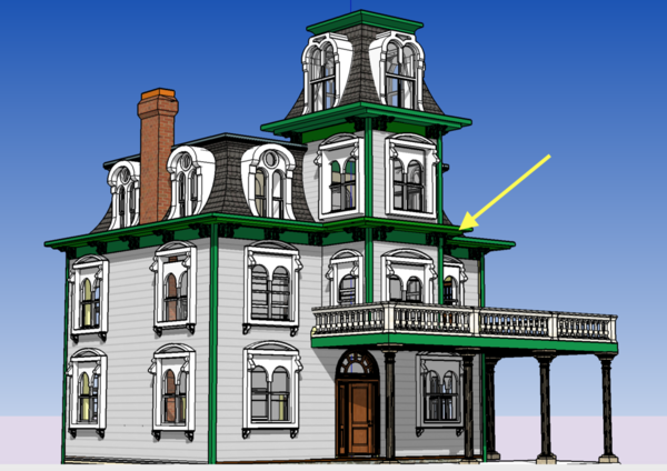
I'm thinking out of the box a little and am trying out different color schemes going a little more wild. In Lambertville, NJ and Montreal, Canada I've seen houses of this age with some more radical coloration like this street in Montreal.

Montreal 18 Neat Houses

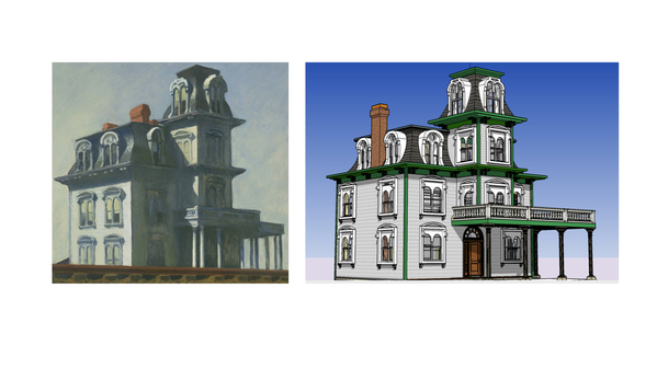
Here's one way it could look. I've also tried more violet, but my spouse didn't like it. What do you think? And be honest!

Screen Shot 2020-09-26 at 12.05.46 PM

Attachments

Images (2)
  • Montreal 18 Neat Houses
  • Screen Shot 2020-09-26 at 12.05.46 PM

Add Reply

Post

OGR Publishing, Inc., 1310 Eastside Centre Ct, Suite 6, Mountain Home, AR 72653
800-980-OGRR (6477)
www.ogaugerr.com

×
×
×
×
Link copied to your clipboard.
×
×