I am insane, but then, in one way or another, everyone I know is insane, just not institutionalized. Having a lifetime project is the general idea. I'll do it until the eyes and hands give out. I have no idea how these metric jeweler's sizes compares to English. I even have some miniature taps that I bought from MicroMark years ago that I've never used because I don't have matching dies. I'll keep experimenting with this jeweler's set to see if I can produce something that works. I went on Google to actually find the tap drill and o.d. of these sizes, but didn't succeed...yet.
They have cut a lot of funding to all the state institutions, I think we are all safe for a good while yet! ![]()
I think you're right. Besides, there's a lot of folks that should go before obsessive model builders.
I finished the MV disconnects today and epoxied them to the gantry. Before doing that I masked the upper works to leave them natural metal when I spray the whole deal sky gray. I then started building the chain link fence. Dennis Brennan first has you build the jig that will align all the pieces. While the standoffs on the jig were drying I painted the substation site "earth tan" and generously sprinkled "earth" on top. Earth on my railroad is Woodland Scenics fine brown ballast. I know some folks really use dirt, but I'm not going to impose on the other person that lives in this house to let me use the oven to bake out all of the organics likes you're supposed to do. After I lay down the "grass, etc." the brown ballast is not conspicuous.
Here are the MV disconnects setting up. I'm glad I checked them before coming upstairs. Two of them had flopped over. The epoxy wasn't set yet so I was able to stand them back up.
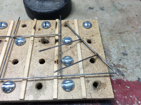
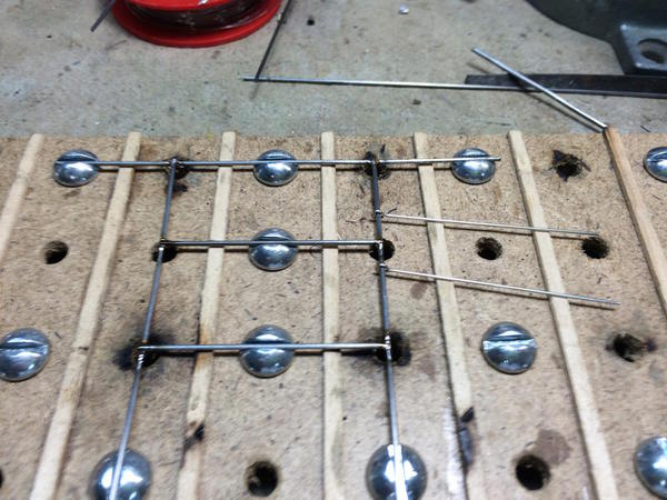
This is the jig plate for the fence building. Screws and nuts go into the holes that clamp and position the vertical and horizontal fence members. I put a granite surface plate on top to hold these wooden standoffs while the Aleen's glue dried. That's the surface plate standing up behind the jig.
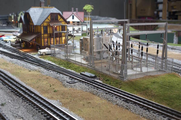
Lastly, here's the site getting ready to accept the substation.
Little by little, the layout's bed rock is being covered over with land and life.
Attachments
Looking good. By the way, your project management skills are first rate, too.
Just amazing detail on everything you do.
I appreciate all the compliments, and especially for my project management skills. While I was technically a "training director" in my professional life, I managed many large projects, made extensive use of MS Visio's Gantt charing capability, and took pride in logically organizing the steps. While I don't go as far to do gantt charting for my modeling projects, I unconsciously lay out the steps in the same logical fashion. As I noted several times before, part of the fun of scratch-building is that what-you-do-before-what is entirely up to you. I love big plastic models with 500+ pieces and the great instruction books that accompany them, but I also love the challenge of figuring all that on my own.
With all the computer stuff out of the way, i first had to do a couple of home projects. The first was repairing the Corian kitchen sink. It had some dings and small knife point cuts that come from occasionally dropping stuff when washing dishes. I did some research on it and got nowhere. So I thought about it for about a year and decided last night to do something about it. First I bleached the dark color out of the small cuts using Clorox in a syringe. I dried it and then mixed some epoxy and micro-balloons filler. I used the filler mainly to turn the filler white. I thought about using CA, but realized that it doesn't hold up in hot, soapy water. Which is why you can't fix china with CA if it's going to be used and put in a dishwasher. After curing all night, I sanded the epoxy down using 180, 320 and 600 grit sanding sticks. They're now almost invisible.
Then I replaced all the packing and bearings inside out Kohler faucet that was leading around the stem's base. I had replaced o-rings on this two years ago and at the same time obtained a complete rebuild kit from Kohler. It was leaking badly so it was time to rebuild it with the kit. No more leaks.
Then it was down to the shop. I epoxied the MV breaker to its base and while it was curing started construction of the chain link fencing. Brennan's kit has a jig that uses strategically placed 1/4" holes which get 1/4" nut and screws. At first, having not actually read the first couple of paragraphs in the instructions, thought the fence rods went under the screws. Nope! They drop into the aligned slots on the screw heads.
I'm cutting the mild steel rods using a Xuron hard wire cutter. It cuts mild steel like it was butter. I then square the end up with a cut off wheel in the Dremel flex-shaft held in the Pana-vise. I found it a bit more challenging than I expect to solder the rods together using the RSU. It has difficulty applying heat to both pieces at the same time. If I grip the parts diagonally across the joint so the current flows through both pieces, it pushes them out of alignment. I may have to revert to an iron for this job. We'll see.
Once the epoxy cured on the MV breaker it was time to paint the breaker and gantry.
I also added insulators and did some minor detail painting (plus adding a logo). I also added insulators to the gantry and with that, all operating apparatus is complete.
The last thing I did today was paint the "concrete" bases and the parking pad concrete color.
I can't glued anything down just yet. I want to drill all the fence post holes in the drill press first, then I can glue everything. I think I'll put in the gravel before running the bus wiring since it will be easier to get into things without wrecking the wiring. We're getting close now. I suspect the job will be done before we head Back East for the Holidays.
Attachments
It is looking mighty good!
This looks soooo real! It is reminding me of work twenty years ago. ![]() Very early in my career I was in technology and software at (W)-ABB, but as I time passed in ABB I realized you had to be in "big steel" to get anywhere in the company - (I often joked that the company did not understand products unless you could paint them). I moved to the product divisions in 1990 and both enjoyed it more and had more success - too much it turned out - everyone wants to be at the top or the org chart with the corner office but its the most boring job in the world. That's why I retired early from it and did something else. The fun jobs are out in the field with equipment like this . . . not in a conference room with spreadsheets and powerpoint presentations.
Very early in my career I was in technology and software at (W)-ABB, but as I time passed in ABB I realized you had to be in "big steel" to get anywhere in the company - (I often joked that the company did not understand products unless you could paint them). I moved to the product divisions in 1990 and both enjoyed it more and had more success - too much it turned out - everyone wants to be at the top or the org chart with the corner office but its the most boring job in the world. That's why I retired early from it and did something else. The fun jobs are out in the field with equipment like this . . . not in a conference room with spreadsheets and powerpoint presentations.
Fantastic work . . .
I've been lurking here, very interesting, inspiring work. Reminds me of helping Gramps make some pressure/temp gauge parts (rod/arms).
Lee, now you know why some folk just like to paint everything. I think you must have got reverse Tom Sawyer-ed in a way![]() . Oh well, just think about the $tacks of fun you have today though
. Oh well, just think about the $tacks of fun you have today though![]() .
.
We are absolutely on the same page! As I moved up the training management ranks I missed the field more and more. My best job was the first one in industry where I was working directly with the folks on the factory floor, both training and solving processing problems. The more academic the training became the more I became less enthused. I had to be persuaded to do management training. While it was a great professional boost in both rank and $$$, it was significantly less fun to a hands-on person like I am. Now, when I'm in the shop almost every day, I am the happiest that I've ever been. Any pressure I feel is self-imposed.
I'm even getting used to the MAC. To copy on Windows, you use the CONTROL KEY which is the lower left corner of the keyboard. To copy in MAC you used the OPEN-APPLE KEY which lies next to the space bar. Every time I copied yesterday my little finger jabbed at the FN key and nothing happened, then I hit the right one. It will take 21 days. When I moved to Germany they gave me a laptop with a German keyboard. Besides having the German accent keys in regular places, they also reverse the position of the Z and Y. The Y is rarely used in German. My real name is Myles. I was typing MZLES for 21 days before my fingers re-learned the new pattern. Then when I got back to the USA, I was again typing MZLES for about 3 weeks. Very annoying!
Boy... Have I digressed! It's morning and I'm not in the shop yet. When I go I will post again.
. . . Now, when I'm in the shop almost every day, I am the happiest that I've ever been.
Same here. It was worth all those years of crude getting to retirement (even though I am only at half).
I suspect you were saying "Crud" not "crude"... Likewise.
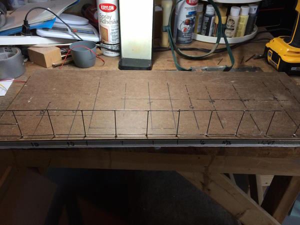
Got into building the fence. Much more challenging than I would like. I first tried the RSU, then switched to the Weller iron with a broad tip and then quickly back to the RSU. Getting the pieces fit was not too difficult. Soldering them the first time was not too difficult either. But when i was attempting to clean up the joints with the sanding sticks, things got dicey. Butt jointed solder joints with thin mild steel rods are not very strong. If the joint got flexed, nine times out of ten, it let go. The joints would be much stronger if they were silver brazed, but I don't have the equipment. They would also be stronger if one bar lapped over the other, but that's not how Brennan's design works, nor is it how the prototypes are built. So I soldered, and re-soldered, and re-soldered again. Making it more challenging is the length of the long side of the substation is 24" which is twice the length of the assembly fixture. So I had to join one finished section to another and keep it going. The first long section is almost done with one more bay to construct. I'm not looking forward to joining sections at the corners since it's soooooo easy to de-solder the adjacent bar while trying to do the next one.
This is the first panel I completed before the middle brace bar at the terminal post on the left.
Here's the second panel attached to the first, with the 2nd panel in the fixture. I have one line post to install on the right end and then the corner post. The last bay is shorter than the rest to fit the base plate properly.
I use weights to hold the bars steady while applying the current to the RSU. As I was moving along the solder joints did get better. If the solder doesn't flow properly right away, it probably won't be a good joint. The RSU can make the metal very hot, very fast which is good as long as the solder flows. If it doesn't, the flux oxidizes and the joint becomes resistant to soldering. It's all about timing. It will take a couple more days to construct the full perimeter. The fencing is bridal tulle and there are eyebolts to hang gates.
I'm also learning more and more about the MAC. I found that you can do all the picture editing I'll ever need right in the Photo Previewer. I don't need Corel PhotoPaint any longer which is good since Corel doesn't make a MAC version and I don't feel like springing for the Adobe suite. Speaking of Adobe, you can no longer buy the software, you must rent it for $10 a month through their cloud. Since I'm a hobbyist and not using it professionally, I really don't like having a perpetual $120/yr fee to edit photographs.
Attachments
Oh wow! Now you really ought to do an article about how you build that fence. Brilliant idea. Maybe only a few people will every build a substation, but a fence. EVERYONE wants to build a fence. You really should think of doing an article.
Oh wow! Now you really ought to do an article about how you build that fence. Brilliant idea. Maybe only a few people will every build a substation, but a fence. EVERYONE wants to build a fence. You really should think of doing an article.
I second Lee's suggestion. That is a slick jig Brennan includes. I agree, I would have thought the screws were to hold down the material, but placing it in the slots is slick. Sounds like one must hone his skill and have the patience of Job to build this kit. ![]()
Thank you once again for the documentation.
Also, that is pretty slick how you fixed the dings in the sink. I never knew what to do about it. Now I don't have to worry. My in-laws installed a stainless double sink when they had the kitchen remodeled a few years before my father-in-law passed away. Then my mother-in-law sold us the house. I like the stainless sink.
I'm writing articles for O'Scale Mag on the entire sub-station project. I've submitted three parts so far and have been paid for one. I'll include the Chain Link Fence too. Needless to say, unless I have more luck with it, I may not want to publicize it at all. This is a typical event:
If this happened once, it happened 20 times! I spent over two hours on Friday breaking and re-soldering one joint after another. As I noted before, a butt joint with 3/64ths steel rod using soft solder is a recipe for disaster, and disaster struck over and over again. I was trying to position it over the base board to mark the post locations, drill some holes and see how it would look. Every time it flexed a little bit, some joint would let go. Sometimes it was just a cross-member, other times, like the above, it was whole chunks letting go. Finally I got it to stay together long enough to get it on the base. I enlarged the mounting holes so I wouldn't have to put any undue pressure on the fence to get it in. I think I inject Gorilla Glue with a syringe once I'm ready to mount it for good. Gorilla Glue is a polyurethane and expands quite a bit when cured. It would fill up any gaps.
Here's the raw fence on the first (long) side of the base. It's that 24" length that caused most of the troubles.
I tried a couple of different ways to get the solder onto the joint. First I was feeding it from a very fine 60/40 wire, with mixed results. Then I cut chunks of non-lead plumber's solder and put a chunk on top of the joint, hit it with the RSU tweezers and waited for the joint to get hot enough to flow the solder. This worked, but it was frustrating to get the solder to stay still just sitting on the junction. Finally, I started wrapping the cross-members with the fine solder which holds it in place long enough to melt. This method seems to be working okay. Because of the small surface area of the butt joint, you have to build up a pretty large fillet to gain some more strength. The RSU gets the joint so hot, so quickly, that if the solder doesn't flow right away, the joint starts to oxidize badly even with the liquid flux.
If this was jewelry shop, which it ain't, I'd try and laser-weld that joint. That would be the way to do it. If not, silver braze it with a micro-torch. But soft-solder just isn't so strong. If I could make cross lap joints in the steel and multiply the surface area that could work too, but would represent an inordinate amount of work. Dennis Brennan's instructions call for it this way so somebody out there must be successful.
Frankly, I'm not sure what I'm going to do at the corners. Wires at 90° will have to join the same post AND you won't be able to use the fixture since one leg will be sticking straight up in the air. I know that as soon as I get one side on the other will let go... that was happening all day. I'm almost tempted to cheat and have double posts at the corners. Again, if there were lost wax cast sockets (like the prototype) that the rods could seat into, soldering would go much faster. Also, I'm almost tempted to make the whole thing out of brass anyway. It would be much easier to solder. It all gets painted with primer and then finish color so the color of the metal is moot. It would take over 25 linear feet of brass rod to do it. I could still use Brennan's fixture.
One of the values of writing this treatise each session is it gives me time to think, and the more I think about it, the more I'm going to try to use cross lap joints instead of the those butt joints for the bottom rail. The top rail is continuous so it's stronger.
Attachments
Trainman,
Congratulations on getting the articles published in O Scale Magazine!
Your substation project is certainly worthy!
Flaws and all, your fence is looking better than any I have built. I will follow this with interest but frankly may not follow you in building it: there are some things that are just so dang difficult to do that it is not worth doing it (in my opinion) more than necessary. I've done cheap-shot chain link fences that looked good enough from a few feet away that I left them on the layout. I think I will just avoid putting chain link close up to the edge of the layout where someone can see the flaws. What you are oging through looks quite time consuming and frsutrating, frankly.
Good luck with it though. Great work, as always.
And fantastic about the articles!
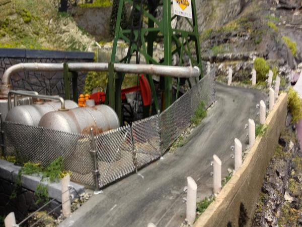
Nice use of the Lionel oil rig! I really like it.
I do not recommend trying to make fence sections longer than the jig. I have tried it and the section is too unwieldy. As noted in my instructions, to cover an area longer than the jig (12"), separate complete sections should be carefully fit-butted up next to each other without soldering. The same is true for corners. The prototypical design allows for this without resorting to double posts where the sections abut.
As far as soldering, I'm not a soldering expert and the instructions assume you've never done anything like this previously. If you follow the procedures that I've laid out, one should have no problems. Having said that, Trainman is correct about butt joints being delicate. That's precisely why an individual section should not be any longer than the jig. There are trade-offs when it comes to designing a prototypical chain link fence. Patience is required, however, the end result is an extremely realistic model that will stand up to close scrutiny.
Attachments
Congrats on the OGR articles, this project certainly deserves to be featured, it a masterpiece!
I too think using the oil derrick looks terrific and I really like that lock and chain! I've only have approval for one article of the series so far. I've submitted three and have several more to go to finish out the whole project. I'm expecting that it will all be published in full, but haven't heard as such.
Dennis Brennan and I spoke on the phone last night about the challenges I was facing in soldering the steel frame for the Chain Link Fence. I really appreciated that he personally answered an eMail I sent him requesting some help. He's a pleasure to work with!
I continued to evolve my technique and have been grinding a small radius so the rod nests into the other piece. This greatly increased surface area and made a much stronger joint.
I've also gone back to the Weller Soldering Station set at #4 with a wide tip. I found that the RSU was unable to heat all of the joint elements at the same time and therefore, caused very poor solder flow. I've also gone back to using the TIX flux, and feeding solder from the spool. The above pic was the last time I used the "solder-wrap" method.
While I was doing this, grandsons were over for nice long work session. #1 grandson is building a 1:350 Trumpeter USS Hornet in Jimmy Doolittle configuration. He's doing this kit while waiting for the replacement Hasegawa F-22 Raptor decals to come from Japan. And #2 grandson did several things including adding vegetation to the area around the substation site, re-doing and adding ballast around the train station, and then we broke open the box holding my Westport Modelworks fire house kit that I bought from Les Lewis at York many years ago.
I hadn't started this model because some of the resin walls were badly warped and I just wasn't sure how to approach it. Today, grandson and I worked out a plan and he executed it. We're CA'ing Plastruct structural parts left over from the bridge building projects. The "I" and "H" beams had enough stiffness to pull the resin nice and flat.
For the long walls we did the same thing. In the pic below, you can see where we had to rip off the side pieces and shorten the cross-member and then re-qlue. The beams fouled the corner when we did a trial fit...Doh!
It may still be a problem because it will be hard to install corner bracing, but we'll figure something out. He learned how to use razor saws, the miter box, CA and accelerator, measuring and cutting multiple parts using a bench stop. Both kids do excellent work and days like this are so special and I know they won't last forever so I take them when I can get them.
We were going to head back East on Christmas Eve day so my shop work was going to end tomorrow, but we've changed itinerary and will be leaving on the 26th so I may get more work this week. Goody!
Attachments
Because our trip back East has been moved out a couple of days, I actually have some more building time. Today I finished reinforcing the other firehouse wall, cleaned up the mitered surfaces of the resin casting, and then put it back in the box until I'm done the substation.
I changed my chain link fence scheme one more time and landed on one that really made the assembly go together more quickly and resulted in a stronger assembly. While I'm violating Dennis' scheme a bit by using a continuous piece for the bottom and top longitudinal members. I notched them at each line post so they aren't actually stuck on top of the posts, but settle in a bit, but they're still not run from post to post like Dennis suggested. I made an executive decision. I really wanted to get this fence constructed and finish the substation, and I didn't want to get more bogged down.
Here is the cuts that I'm making in the longitudinal members and posts. The two nest together nicely, provide much more soldering surface area and create a much stronger structure. I wish I could go back and do the first one over. I will if I have enough stock or substitute brass for that one side.
I was able to build the 2nd side (both halves) and the 2nd end in half the time it took to make the first section. Steep learning curve!
I laid out the locations of the mounting holes very carefully and because of the much stronger structure, it plopped right in without anything breaking apart.
Following Dennis' advice, I did not attempt to solder the two panels together (each 12"), instead, they're just butted up against each other. I will probably use some CA to hold them after the fencing cloth is in place.
The placement of this long side was based on the short end piece. It had to butt up to it in the corners.
I then laid out and measured for the remaining short side which will have the gate. The gate opening is 4 1/4" wide to accommodate 2 - 2" swing gates. I couldn't help myself and temporarily stuck the base back into its socket on the layout. It's not pushed all the way in since it's hard to remove it, and I didn't want to break anything.
It's also in backwards. The opening will be at the station side. Shown also is the concrete pad that will provide service truck parking. Next up will be the gates, then clean up all the flux and primer paint. From there I will add the diagonal bracing with CA, and then add the bridal veil tulle. And then a final painting and installation. It shouldn't take longer making 24" of model chain link fence than installing a real one. I think the finished fence is going to look very cool and really add to the industrial nature of the substation.
Attachments
Looking at this I keep expecting a car to go by.
The crop, and the track are the only things holding this back from being indistinguishable as modeling.
All its missing from life is some wind blown leaves at the fence base, and kids exploring the unfinished construction area ![]()
Beautiful!
Merry Christmas!
You're doing a great job. The way you're doing the bottom rail will essentially result in same look and at the same time be stronger! Bravo! It tickles me to see you modify my design and run with it. The bottom line is that you will end up with a realistic chain link fence that you're pleased with and fits in with the rest of your superb modeling.
Thanks Everyone, and Dennis!
I had enough material to rebuild the first side completely. It just wasn't working for me and I had three other sides that looked much cleaner. Plus it was still breaking. I then built the gates. Of course I didn't read all of Dennis' instructions about the gates until I was ready to build them and then saw about leaving the end post off of the main fence to captivate the hinges. Instead of un-soldering them and making another mess, i put the eye part of the hinge onto the gate side and did it as Dennis instructed.
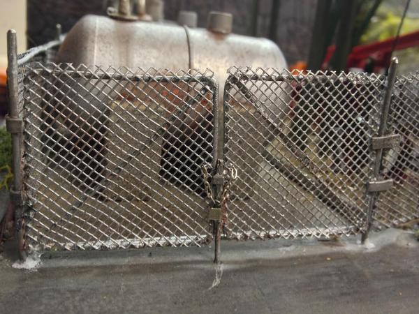
Here's the re-made fence, made in two parts that will be butted together upon installation.
You can see that it's nice and straight. I cross-lapped all the joints so, even though the bottom bar sits a little proud of the line posts, it's not sticking out as far as it would if I didn't notch both pieces. I'm using a fiber cut off wheel in the Dremel flexi-shaft which makes it easy to do the notching. Wear goggles when doing this.
Here's the first gate being built.
The solder joints are coming out nice and clean. I use some v-blocks to weigh the pieces down when soldering. This is one application where a traditional iron works better than the resistance unit. I have many tools...each does what it does best.
Here's the first set of hinges in place. I could have done this phase a bit better. It's functional, but not pretty.
Dennis shows keeping the part near the eye parallel and then wrapping the tail around the fence members to stabilize. When I tried this, it distorted the eye's position, so I resorted to using black iron wire, twisted with a forceps, to hold things still during soldering, I had to be fast so the corner connection didn't de-solder. It didn't!
And here's the gates in position for a trial.
Dennis suggests priming all the steel before attempting to CA the remaining details and the fencing cloth, so I cleaned all the joints to remove the excess rosin flux, first with acetone followed up with alcohol. Then laid them out and primed both sides with Krylon primer gray.
This wrapped up work for the day. Not being of the Christian faith, tomorrow is just another day, except for all the stores are closed, so I may get some shop work done. We're heading back East on Friday morning so some of the time will be spent packing, but I might get some stuff done. And for all of you of the Christian faith, have a very Merry Christmas!
Attachments
Hope everyone is having a great Christmas. Me, I've had a wonderful day also culminating in going to our local Chinese restaurant for take out and seeing a 1-hour waiting line. It's their busiest day of the year. Luckily, takeout came in a normal time. And I did get about an hour's work done on the fencing.
The fence frame is now complete waiting for the bridal tulle "chain link fabric". I was going to start on that also, but then realized that I was about to rush it, and thought better of doing that and went back upstairs.
What was done today was adding the simulated tension rods where the fabric terminates at the end posts, and the diagonal bracing also near the end posts. This was all applied with CA on the previously primed metal.
The fence fabric has to be carefully trimmed taped down on a cutting surface. You need to catch the trim line just above the points on the tulle fabric. This requires a lot of care and I wasn't prepared to spend that much time today. It will have to wait until 2015. Then this whole 5 month project will come together quickly. Of course I still have hook up all those bus bars...
So everyone, until next year, Have a Happy New Year!
Attachments
Just checking in... got back from our trip back East yesterday afternoon, and today was taking it easy. I got the word from O'Scale Mag that we're going with a 6-part article series on the substation build. I've completed three parts so far. The remaining 9 phases will be folded into three more articles. Tomorrow's going to be cold and a good day to work in the basement. The colder it gets, the more often the heater is on. The more often the heater is on, the warmer is the basement.
Speaking of heaters. We returned to a house that was 51 degrees inside. I had reduced the temp to 66, not 51, before we left. At first my wife suggested that I turned off the heat instead of just setting the temp lower, but after the furnace ran for 15 minutes and only cold air was coming out of the registers, I began to get worried. I checked the unit, opened the panel, it shut off, heard the inductor blower start, heard the gas valve open, and then the ventilation blower start, but no heat and no flame. I have a service contract on the unit and called. The tech came at 8:30 and immediately knew that the ignitor had failed. He had two different ones in his pocket. The one that actually fit was in his truck. Problem solved... and just in time too since it's going into single digits tomorrow. Central heat is like air and water, you don't think about it too much until it's not there.
Tomorrow I'll be back at work finishing the fences.
Glad you got home in time to get the furnace going. We had ours freeze once 30 years ago.
I'm glad to read you got 6 articles.
Congratulations!!
. . . . the ignitor had failed.
For some reason our first floor heater blows its ignitor every year, around the time we first use it - usually November - it goes within a few days of our first using the heater. The heater for the upper floors never has burned an ignitor. . . Anyway we just replace it now at the beginning of winter, every year - the service contract people we have, after about fifteen years, learned and do it at not extra cost now -saves them a trip later - - and we don't go away on a trip until we have, just in case.
A furnace is something you definitely do not mess around with. Mine is cleaned annually. You need that trainroom warm & cozy.
You may want to consider keeping an extra igniter. Its cheap piece of mind. Even HVAC people get stuck in blizzards. Ask me how I know![]()
I think dust, cooking oils, etc. collected on less used ones can crack the surface as they burn off during first reheat. Or you might have a board issue correcting itself after the first repower. Cooking oil seems to be a major reason in my mind. The hot surfaces are oil sensitive.
We do have the HVAC system serviced twice a year at the season change, and I agree that buying an ignitor and having it ready to go is a good idea. It's easy to install since I watched the tech very carefully just for that reason. The weather is really cold today and we're sure glad it failed when it was in the 50s, not the 10s.
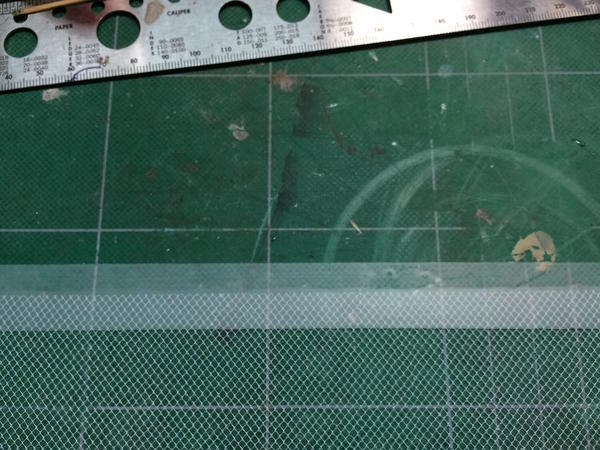
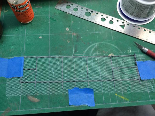
Did some errand so I only had a little over an hour today, but it was enough to get some fence fabric installed. It's tricky to trim the tulle so the diamonds are all on the same row. It's very easy to lose your place when you try and align the fabric along the guidelines of the cutting pad. I took my best shot. I used Scotch Magic tape to hold the fabric in place and cut through the tape so both cut edges were supported.
The fabric is held to the frame with CA. Here again, because I didn't fully butt solder all the members, some of them are higher than others so gluing isn't 100% on every member, but enough to support the fabric.
Here's the next piece added and placed into the holes on the base.
You'll notice a gap where the two panels join. That's because there's no vertical post on the one panel so the fabric ends in open space. I'm going to try and glue that piece to the neighboring post when I glue the posts into the base.
There's also one other minor problem which I'm not going to fix. I put the fabric on the inside of the fence. It probably should be on the outside, but again, because of my post/cross-member soldering scheme, the best place to glue the fabric was the inside on the first piece and I was then committed to doing that since you can't have it on the inside half the time and the outside the other half. It looks good and it's not even painted yet. I'm going to airbrush a mixture of silver and light gray to simulate galvanized steel. Spraying will be done with the fence mounted on the base so I can get to both sides and not have to handle it. The fabric installation is 50% complete and will be finished tomorrow. I will then mount and paint the fence and start installing equipment.
I bought some more aluminum small solid rod to use as the bus bars. I'm going to experiment with using the solid or tubular material and see which one works/looks best.
Attachments
I think the fence looks great. Also, this is a dang good tutorial on making a fence. I'd want to practice some of the steps before attempting one, but the great thing about this thread is that it shows a person what to practice, and how.
Anyway, I think it looks superb. Just great.
Thanks Lee! The fence looks great, but... As usual my great skills are tripped up by overlooking some basic piece of information. The Substation base was plastered into the layout with a specific orientation, and it was set up with the gate on the train station side. Then when I started drilling the base for the fence panels I had reversed the direction. I drilled holes and laid out the entire fence placement BACKWARDS! This put the gate at the opposite end of the base. This would be no problem if the base were completely symmetrical I could just drop it into the plaster socket in the opposite direction. It's not symmetrical and did fit reversed. Therefore, I had to re-locate the entire fence. When I first did this, the gates were 1/4" apart so I had to skew one fence panel to bring them into alignment. Alls well that ends well...
The holes were filled and the non-linear part will be landscaped so the finished job won't be as noticeable as it is now.
So all the fencing is complete. I installed it all temporarily into its holes and airbrushed the whole lot a mixture of flat aluminum and sky gray. The aluminum doesn't show up too well, but it will have to do. I might dust it with some rust to tone it down a bit.
I thought I'd show some more of the intermediate steps to illustrate some of the points I've made over the past few days.
Here's how I tape down the tulle in preparation for cutting. I did find that some of the tulle's edges were sufficiently straight to not need further trimming.
Once the top edge is cut, I tape down the fence frame and then tape the tulle over top aligning the top edge. I put some tension on the tulle do it lies flat. You start by CA'ing the top corner and the edge that touches the tension arm. The tulle doesn't get glued to the corner posts, but terminates on the tension arms. Speaking of the tension arms... the CA is not holding them on very well. Even though Dennis suggests priming first then CA'ing, I had to re-cement them many times. If I did it again, I'd try my best to solder them in place.
Use a very sharp single-edged razor or a new Facto to trim the fabric close to the edges.
For the gate that's 90° to the fence to which it's attached, I added a separate piece of tulle since the gate lay at a different elevation than the rest of the fence. For the other gate that was in line with it's attached fence I covered the whole thing with one piece of tulle, glued it all down, and then separated the gate section from the rest in the trimming operation.
Even with everything glued, it's all very, very fragile. As a result, I'm going to do everything I can to complete the entire project before finally permanently adding the fence.
Here's the painted fence.
After dry, I took all the fence pieces out, filled the errant holes, and cleaned up the base from all the over spray. I then glued down all the operating pieces.
I used Titebond glue to hold everything in place. Since all the foundations are wood, it's the right cement to use. I still have to glue the transformer down to its pad. Since its under frame is plastic, Titebond is not the right cement. I may go back to epoxy as I used on the other pieces. While lying bed last night, I realized that I haven't built the lighting yet, and with all the apparatus in place, it will be a more delicate operation running the wiring underneath. Doh! I should have held off just a little bit more before gluing everything down. That proves that I'm not as patient as my reputation seems to warrant. I am persistent or tenacious which accounts for my ability to keep going. But I'm not patient.
With all the apparatus in place, here's what it all looks like.
So today, I will epoxy the transformer today and start working on the lighting design. I'm going to go with blue-white LEDs since they'll more accurately depict mercury-vapor lighting. I could go with the white-white LEDs if I want to simulate incandescent lights. Any opinions out there? I'm also trying to decide what form and where they will be on the base. I think I'll do some more research on this.
Attachments
Today I epoxied the main transformer and while it was curing, started working on the lighting design. I'm was going to go with blue-white LEDs since they'll more accurately depict mercury-vapor lighting, but I only have 5mm ones and they're too big. Instead, I'm going with 3mm white-white LEDs which will simulate incandescent lights. After looking at some of my research pics, I noticed they're using some kind of light poles. I was thinking about using some gooseneck lights, but my brass tube was too narrow for the LED wiring to pass through, so I went with a larger 1/8" diameter brass tube which will be a light pole with both conductors going through. I just have to insulate the positive leads. The negative leads can contact the pole. I was going to use the pole itself for the negative, but the upper solder joint wouldn't work as I wanted.
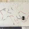
I drew a crude diagram of what I'm doing. The nice thing about LEDs is NO HEAT, so they shouldn't melt the plastic. In the "old" days grain of rice bulbs could not be used in a plastic assembly such as this one. I tried illuminating a Plasticville signal bridge with grain of wheat bulbs in 1958 with not-so-successful results. The light housings melted!

The top and bottom of the fixtures are styrene disks punched out with a hollow punch. There are two sized disks. These are the large ones (9/16") along with the punch that made them. I also punched out the inner disk with a 7/16" punch. These two are glued together.
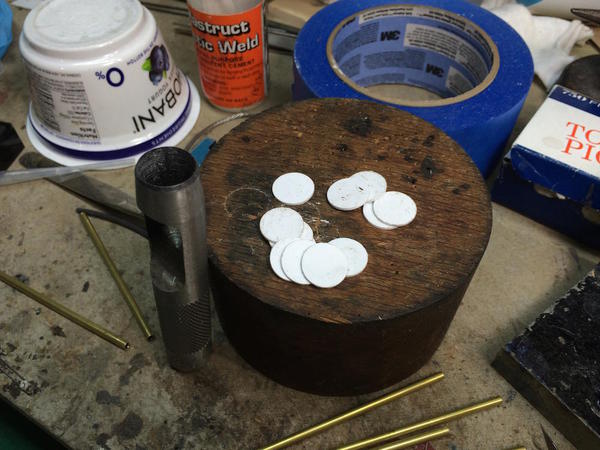
The inside of the top is now reflective by adding some Bare-metal Foil. I'm making the "glass" enclosure with .005" styrene sheet wrapped over itself and glued, then captured between the inner disks. The way to apply these thin adhesive foils is to lift up a bit on both sides, attach it to some scrap paper strips which lets you carry the foil and place it without it curling and folding over on itself. You see the strips in the pic before trimming the foil around in the inner disk.

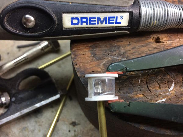
It was a bit dicey getting the enclosure glued properly. It takes a very tiny amount of solvent cement. My first attempts melted the plastic clean through. Surrounding the clear styrene is some Scotch Magic Tape to give a frosted appearance and diffuse the very bright LED light. I'm wiring the four light fixtures in pairs so I only need one 330 ohm resistor for each pair in series. I'm going to have to drill holes in the base with the apparatus all mounted. Doh! However, I tested the whole deal and everything is very secure so I will be able to tip it over—very carefully—to do any wiring underneath. Wish I would have just planned this a wee bit better...

I made a lot of plastic blanks for the enclosures so the gluing will get better. I first tried to make the "glass" wrap around once using the inner disk's diameter and Pi, but it's way too springy and would be difficult to install. I then added 0.100" inches to the length to give some overlap. I clamped it with some spring tweezers and used the Touch-n-Flow glue applicator, but it's putting too much on. I'm going to with a fine paint brush for the rest of them. Here was a mock up that I slapped together to see how it would work. I didn't have the Scotch Tape on this one.
Right now I'm going to find some "High Voltage", "Do Not Enter" signs on the Internet and print them out for attachment to the fence.
Attachments
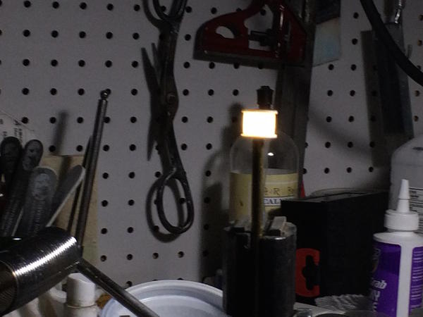
Worked on the lampposts today. I went to a larger sized tubing so all the wiring, solder joints and shrink tubing would fit inside. I only had one length of it so I could only make two posts. I'll get some more 3/16" brass tube tomorrow to make the rest. I'm wiring two in series and it needs a 330 ohm current-limiting resistor for the 12 vdc input voltage I'm using to retain the 20ma current through the LEDs. Here's one being illuminated.
It's hard to get a good exposure of an illuminated object using an iPhone. They do throw a lot of light. In real life the light is not as diffused as it shows here, but it is diffuse enough to hide the imperfections in the clear plastic enclosure.
I have some questions about posting on this (or any other forum). When we put pictures up on the the forum, whose property are they? Are we giving them ownership of our work by the act of posting? In other words, what are the copyright rules regarding posting on forums like this? If by posting we're giving tacit approval of ownership, I may have to reconsider what I do here.
On a lighter note, I had a visitor on Sunday. The five-year-old son of a colleague (and his dad) came to see the trains. He also visited last year, but it was a little overwhelming. This time it was all "Wow!" and "Cool!". His eyes were popping out of the his head. I'm going to donate the entire set of "I Love Toy Trains" to him. My grandsons at that age were obsessed with them.
While running the trains, we detected a defect that kept derailing my N-S F7 Demonstrator hauling the passenger train. There was a vertical misalignment between the outer loop track as it crosses the swing-gate hinge end. It measured 0.045". Instead of attempting to pry up the track and shim it, which would be difficult since it's all ballasted, I took advantage of L-girder construction. I made a 0.045" thick styrene shim, loosened the two screws holding the cleat to the OSB sub-roadbed, put in the shim, and tighten it up. Misalignment gone.
Attachments
While running the trains, we detected a defect that kept derailing my N-S F7 Demonstrator hauling the passenger train. There was a vertical misalignment between the outer loop track as it crosses the swing-gate hinge end. It measured 0.045". Instead of attempting to pry up the track and shim it, which would be difficult since it's all ballasted, I took advantage of L-girder construction. I made a 0.045" thick styrene shim, loosened the two screws holding the cleat to the OSB sub-roadbed, put in the shim, and tighten it up. Misalignment gone.
Smart. Good thinking.
Your substation, as ever, is looking spectacular.
The photos are yours. You are not giving up ownership. However, I would be careful about posting photos that you may be submitting for an article. Magazines generally prefer unpublished material.
Thanks Dennis! As far as the pics, I'll be careful going forward, but regarding the past... there's about 2,000 pictures (literally) already on posts in many forums. We'll work something out. My main argument is that they're reaching different audiences for different purposes. We'll see how it goes. I'm not cutting and pasting my text. I'm writing all the articles from scratch.
My grandson felt that my post lamps looked too city-like to be in the substation. He thinks they should be street lights in the town. I always listen to my grandson. He then offered an idea to use the LEDs with the thinner tubing. His idea was to make a hole in the tube near the lamp end and run one lead on the outside for a little bit and then loop it into the tube through the hole. I started working that idea today and realized I didn't need both wires to run the length of the tube, just the insulated + lead. The - lead could use the tube as a conductor since both leads couldn't fit into this diameter tubing. I trimmed the LED's leads shorter and tried this. The + lead is fully insulated with heat shrink right to the top.
I used the RSU to hold the - lead tightly to the tube while I used rosin-core solder. The LED leads are a bit springy the RSU's clamping action stabilized it until it cooled. I then soldered the rest of the - circuit to the tube's bottom. All of the them tested perfectly. I used a miniature tubing bender to put the curve in the brass tube.
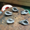
The next step involved making the lamp housing out of Super Sculpey, a clay that hardens when you bake it at 275 degrees for 15 minutes. It was a bit of a long shot. I was originally going to make a master, bake it and then use it to make molds for the rest, but instead, simply modeled each separately. I made six to get four decent ones.
I used the ball peen end of my jeweler's hammer to form the bowl. Here's the rough-made housings.

They're quit rough here, but after baking and sanding they do look more regular.
After baking I finished shaping them using a sanding drum on the Dremel, and then various sanding sticks and flex-files of various grits. They're very fragile! Anywhere there was a discontinuity in the clay eventually broke. I ended up using CA to put three of them back together. I'm also using CA as a filler for pieces that couldn't be re-glued.
I then using wine-bottle lead topping as a reflector. I cut a rough square, make a couple of triangular slices in it and then used the same ball peen hammer to form the reflector directly in the housing. Medium CA holds it in place. I trimmed the overhang with a sharp #11 bladed modeling knife.
No doubt... they're kind of crude.
Here's the first completed one.
When painted, they'll work. I'm going to mount the light poles onto the gantry towers. Meanwhile, the other lampposts will first be applied to light the train station parking lot and driveways. Those miniature white/white LEDs are quite bright and produce no heat.
Tomorrow I will finish them up and paint them. I'll mount them onto the substation and then get cracking on putting in the bus bars.
Lee, I sent you a private message. Did you get it?
Attachments
Trainman, I guess I didn't get your message. Can't find it. Was it an e-mail?
Yes. I sent it to your eMail address on your profile. I'll re-send.
Love the lights, this is really quite a project. It'll be interesting to see it all in print. ![]()
Ray,
I think the detailed work you are doing on this railroad is spectacular. I do not think you should call this the continuing saga. You should rename " the continuing masterpiece'
Alan Graziano
Alan and Ray, many thanks! Because I have been dutifully recording the build progress on this forum, the magazine has rescinded its invitation to write a series of articles. I am not happy about this decision since I think it is fails to recognize the new world of communications in which we live. I believe there is interest in having a bona fide magazine series as well as reading the daily grind I post here. That magazine reaches a different audience, and I like magazines for different reasons than reading things on forums. I look at the forum as a diary with commentary. A magazine article stands alone. It makes me have to reconsider posting other builds that are upcoming for fear that I cut myself off from formal written publications.
Meanwhile, great things happened in the shop today. The lights were finished, painted and installed. They work great and will give great illumination.

They're bright, but not as bright as my iPhone makes them appear. I opened a space in the foam that lies below the substation on the platform to clear the junction block that serves as the wire hookup point. The four lights are wired in a series pair and then paralleled at the junction block. Each series pair works through a single 330 ohm resistor. I relieved the foam core lowest base level to clear the ferrules I used to join the series connections and a place for the current-limiting resistors to nest.
With all of this functioning and complete, I finally was ready to work on the bus wiring. I first tried to go with some thin solid aluminum wire, but when I flattened the ends sufficiently wide to accommodate the hole sizes I would need to connect to the equipment, the aluminum fell apart. I planned for this eventuality and also had some 1/16" aluminum tubing. This, when flattened, had sufficient heft to handle all the holes I would be drilling.
Here's the very first bus connection showing how the ends are prepared.
From this point it went surprisingly fast. I got 80% of the high voltage section complete with only a few more to finish tomorrow.
The tubing doesn't look too big. HV buses are quite prominent and in looking at pictures, it looks similar. Also... nothing looks like aluminum more than real aluminum. All of the turnings, fittings and buses, being natural metal, really works in this instance. When I finish laying in all the HV connections I will go back and CA all the joints. Right now they're just sitting there. I didn't want to glue anything until it was all laid out. When that's done, I will put down the ground cover and put it on the layout. Not before I take some more beauty shots for the portfolio. The fence will go in when it's one the layout. It's too fragile to install and then manipulate the model into position. Something will break. The end is near! And in this case, that's good thing.
Attachments
On the way to a train show Sunday, we drove past a power distribution station. Guess who I thought of ![]() .
.
A step by step, like you have done, is quite long on a forum, and runs a few tangents to boot. I think the interest in a more focused, condensed version would be worth the effort same as a continuation. The only purpose a long one could serve I see, would be a two part story. A good article may sell a few extra print copies, & I doubt anyone would cancel the electric sub. over a few repeats. We repeat facts on a regular basis already, so do the mag.s, its how the new folk learn.
...Because I have been dutifully recording the build progress on this forum, the magazine has rescinded its invitation to write a series of articles. I am not happy about this decision since I think it is fails to recognize the new world of communications in which we live.
I was afraid that would happen. It's not a matter of reaching a different audience, it has to do with exclusivity. That's exactly why I don't publish anything online.
But... let me give you another view. The substation probably wouldn't have existed at all had I not posted the construction. I had no thoughts of taking close to a 1,000 pictures of the construction for an article that was a long shot to be accepted. It wasn't until I started on the journey and got lots of feedback from the forum readers that I decided to keep going. The same goes for blogging the layout build itself. I wouldn't have had a swing out door like it has had it not been for the input from the forum.
The forum is a conversation, not an article. It's like having a bunch of railroaders over the house for a bull session when they live all over the map. I still subscribe to three railroad magazines even though I'm on the forum daily. They're not mutually exclusive and meet different needs.
I still think that the publisher is out of touch with current communications. And I think the articles I already written and submitted would make a terrific series and would say a lot about their magazine's willingness to step out of the typical model railroad mold. It's their loss, and I'm not over fighting for it.
I have other projects in the works, and if, and only if, I get a green light on their publication, I won't post build details and publish a real article. But these projects are very typical model railroad faire; engine house, tavern, model homes I've lived in. The only one that is almost as novel as the substation will be the Bourbon Distillery. The distillery is a long way from materializing since I'm exploring getting some of it laser cut.
BTW: The chain link fence looks terrific, but won't be installed until the substation is in position on the layout. It's still very fragile.
Oh, I completely understand what you're saying.
And, it's not just model railroad publishers. I think you'll find that true of any national magazine. You have the right idea for your future projects. Regardless, one should always check with the editor before preparing an article for publication.
I'm happy that you're pleased with the fence. You're right--it is fragile.
The station under your lights looks so realistic I felt like I was there, just as I had been so many evenings and nights in younger days! The high voltage bus looks great! It has really become quite a project, I don't know if there has been anyone make so much so convincingly for a model railroad.
In reference to the canceled articles, I wonder how many of their readers would have appreciated it for what it is. Yes, it is hard for some to embrace other forms of media. oh well, we have enjoyed the trip, and you have the satisfaction of a job well done!
I surmised as much, that if you hadn't been documenting it so much for us, you may have made it a lot simpler and moved on to other projects. I'm glad you have led us on your journey, but will be pleased to get onto another project with you.
Trainman2001, your postings here and your work is fantastic. No article could cover what has been posted here on this forum. I am not sure why the publisher is being so picky. The details of how you are doing your different projects are lengthy but extremely interesting to those of us who are serious about the hobby. Most of the articles in the magazine are nice but pure fluff. They do not go into detail as you do here. Let alone the number of pictures that you publish. I agree with you that an article could be published with a link to the forum for detailed information for those who are truly interested in excellent craftsmanship.
Trainman2001, your postings here and your work is fantastic. No article could cover what has been posted here on this forum. I am not sure why the publisher is being so picky. The details of how you are doing your different projects are lengthy but extremely interesting to those of us who are serious about the hobby. Most of the articles in the magazine are nice but pure fluff. They do not go into detail as you do here. Let alone the number of pictures that you publish. I agree with you that an article could be published with a link to the forum for detailed information for those who are truly interested in excellent craftsmanship.
I agree, Ken.
Myles, correct me if I am wrong, but wasn't it O Scale Trains that was going to publish the articles, not OGR? If I'm right, they probably wouldn't want to link to another magazine's forum. I am guessing on this, not really knowing anything about publishing.
Gentlemen,
You should understand that an internet forum and a magazine are two entirely different animals. You can do things on a forum that could never be done in a magazine. This build with all of its detailed descriptions and many photos is a perfect example of that difference. Even a series of articles in a magazine can't afford the space to devote to that type of minutia.
The lesson to be learned here, if there is one, is for you to determine who your ultimate audience is and then pick the appropriate platform.
Dennis, Very good point! I think you are exactly right!
Gentlemen,
You should understand that an internet forum and a magazine are two entirely different animals. You can do things on a forum that could never be done in a magazine. This build with all of its detailed descriptions and many photos is a perfect example of that difference. Even a series of articles in a magazine can't afford the space to devote to that type of minutia.
The lesson to be learned here, if there is one, is for you to determine who your ultimate audience is and then pick the appropriate platform.
I do understand this part. And I understand the magazine wanting to have 'exclusive' articles. What I don't understand, since they are two entirely different animals, is why they can not compliment each other. I have read a few articles from magazines on other scales where the article provided links to an authors website for further details. Going to the site, just about the entire article was there and additionally a lot more information.
I suppose I do understand where this being a forum s provided by an O gauge magazine could be a competition thing. However there are so few O gauge magazines, and they are all fairly different in content, I really don't think folks are going to switch their subscriptions. If anything I think they would add a subscription rather than switch to another magazine. I really think O gauge is such a small market there is room for everyone to work together and share ideas and information. However I am not a magazine publisher and have no idea what they are thinking or how they operate. Just adding a few extra thoughts here.
But... let me give you another view. The substation probably wouldn't have existed at all had I not posted the construction. I had no thoughts of taking close to a 1,000 pictures of the construction for an article that was a long shot to be accepted. It wasn't until I started on the journey and got lots of feedback from the forum readers that I decided to keep going. The same goes for blogging the layout build itself. I wouldn't have had a swing out door like it has had it not been for the input from the forum.
The forum is a conversation, not an article. It's like having a bunch of railroaders over the house for a bull session when they live all over the map. I still subscribe to three railroad magazines even though I'm on the forum daily. They're not mutually exclusive and meet different needs.
I still think that the publisher is out of touch with current communications. And I think the articles I already written and submitted would make a terrific series and would say a lot about their magazine's willingness to step out of the typical model railroad mold. It's their loss, and I'm not over fighting for it.
I have other projects in the works, and if, and only if, I get a green light on their publication, I won't post build details and publish a real article. But these projects are very typical model railroad faire; engine house, tavern, model homes I've lived in. The only one that is almost as novel as the substation will be the Bourbon Distillery. The distillery is a long way from materializing since I'm exploring getting some of it laser cut.
BTW: The chain link fence looks terrific, but won't be installed until the substation is in position on the layout. It's still very fragile.
I was just trying to say something similar to DennisB, but you are much better at it than I (and the same goes for modeling). Personally I think the magazine subscribers would be missing a lot by just reading an article of a few pages with a half dozen pictures as opposed to reading your detailed posts here. And you would be missing out on the conversing with and suggestions of all the other great modelers here following the thread.
Sure seems to me like they could very easily compliment one another and everyone would all be better off with a lot more details and knowledge being shared as a bonus.
... I have read a few articles from magazines on other scales where the article provided links to an authors website for further details. Going to the site, just about the entire article was there and additionally a lot more information.
An author's personal website is not a public forum that is associated with a magazine.
Figured the Forum being part of another magazine might have something to so with it.
Great back and forth discussion. Lessons in life are sometimes hard to learn. There's a couple of ironies at work here. First is the impetus for writing a substation article was from you guys. I didn't think about formal publications until the readers brought it up. But of course, by then I'd already posted several hundred pictures and shot myself in the proverbial publishing foot. The second irony is what I mentioned earlier. If it wasn't for posting and the continuous feedback received in this medium, the substation would have come out very different and wouldn't be worthy of publishing. It seems to be a classic "Catch 22".
Since I've come this far, I'm going to finish writing about it and posting pictures. Once complete, there are many other sub-projects to be built besides a large mountain and more landscaping. I've sold my Santa Fe on eBay and got the price I was asking... amazing! With that $$$ I'm going to replace the engine and possibly take the plunge into MTH DCS. I will have 4 engines with Proto 2 (and higher) and the rest with QSI and Proto 1 (one TMCC Atlas which will run conventional). So there's lots to write about. But... I will probably not post any projects that are pre-approved for publication. I really would like to get paid once in a while for doing this to help feed the hobby.
Now back to the substation. As I noted yesterday. I would finish the bus wiring today and I did. I also got the first layer of gravel laid down, but there's some more touch-up work for that. I'm considering doing some light weathering, but I'm not sure where or how much. I don't want to screw anything up.
Here's the complete HV bus system in place and CA'd. The HV system went together much easier than I anticipated, even though I had built it in my head several times. It was really important to make a drawing of this whole affair before building. Even though were some "as built" mods made, the design followed my original drawings pretty closely. Careful consideration to the equipment placement was also helpful in getting a neat looking high voltage array.
It almost looks like it's ready to be energized... I have some high voltage signs to add to the fencing.
I also thought about the MV bus a lot, switching between using small diameter insulated copper wire or black iron wire. I settled on 28 AWG black iron wire. It's easy to form eyes and maintains the bend you put into it. Bus wiring is large gauge and fairly stiff so the iron wire won out. Very small diameter, solid core, copper wire would also work.
There are four different diameters used for connection points throughout the bus system. All the MV bus is connected to 0.032" brass wire except for the connections to the disconnect. On the HV side, there are four diameters ranging from .032" to .061". I had to be very conscious of the bus termination point and drill the correct size hole.
For the MV bus, I twisted an eye using the drill of that size as a mandrel. This worked pretty well.
I formed the eye at one end, bent the wire to the approximate contour, and then wrapped the wire around the terminating end to get the correct length. I would then form the terminating eye around the .032" drill twisting with a pair of needle nose pliers or a hemostat.
Here's the first runs from the MV transformer bushings to the gantry.
Here's the MV bus from disconnects to the breaker and out.
Here's another view.
With the bus wiring complete, all that's left is the ground cover. I temporarily plugged the fence post holes, brushed down some W-S Scenic Cement and liberally sprinkled the surface with fine gray ballast. I then tipped the whole deal over and dumped off the excess gravel and moved onto another spot.
It's a little uneven in spots with the cement still drying. Tomorrow, I'll sprinkle additional gravel to the light areas, wet with "wet" water, and add more scenic cement out of squeeze bottle, just like ballasting track. So all that's left is some light weathering. I'm thinking about having some transformer oil stains under the drain valve. Some oil stains on the concrete drive, but not go overboard. I like the pristine look of a recently built substation.
Attachments
Agreed; enough on the article. :-)
Since your transmission line is imagined, and your high side switch is closed, I would say it is energized! Don't get fried! I say that because it is that realistic.
i agree, I would hate to weather it too much. If you wantEd, you could plant some weeds, maybe brown ones that were sprayed. Also a dead squirrel with a blown off foot laying on the top of the breaker would be too much. Black snakes loved the cable troughs as well. They looked just like control cable, so make sure you are touching a cable not a snake.
it is looking great!!
I don't think I expect weathering as much as some(not all) aged equipment. A fresh paint job but rusty cracks, etc and even new, a few small rust bleeds around some bolts, and seams happens fast. Era and/or "your story" can write any ticket you choose though.
Thank you Trainman, for making your impressive efforts, and having the drive to want to share how you did it with us.
Momentous Day! I am declaring the substation complete! I finished the gravel work, added some very minor weathering, mounted the High Voltage signs all about, and installed the fencing. I reconsidered my decision to hold off installing the fence until it was in place on the layout. I realized there was too much detail work to be done getting it carefully mounted and access to the substation on the layout isn't good; it sits pretty much in the shadow of the control panel. I will have to be very careful when putting it in place. This series of pics was not staged carefully; I just wanted to get some shot. I will set up a better situation and take the "publicity shots" and then take more when the unit is installed on the layout.
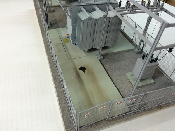
The last truck that parked on the pad left a heck of an oil spot and there was a little seepage from the drain valve on the transformer.

It was a little over 6 months from start to finish. The first post was July 14. Now I need some sound effects... some heavy 60 cycle hum, and the fans turning on and off. I still have to populate it with people and find either a nice Pickup truck or a 1/43 to 1/50 scale utility service truck to occupy the parking area.
Thanks to all for your encouragement, feedback, information, and diversions. As I said yesterday, it wouldn't have either come out this good or looked like this had it not been for journaling the build and all the interaction it generates. I'm going to send OST some pics of the finished job and see if they might reconsider.
Attachments
Well done!!
I really enjoyed the journey you gave to us.
Very fun and informative.
thank you again!!
Now what?
Andre.
Dennis
Piscataway, NJ
On Thu, Jan 22, 2015 at 5:55 PM, O Gauge Railroading On Line Forum <
alerts@hoop.la> wrote:
True craftsmanship!
Trainman,
It is excellent! As I said many times before, I felt like I am right back working in the substation again! The weathering is good, just enough to suggest it is a working place. When you populate it, don't forget to have Mark getting shocked with 220 volts when the cabinet door blew into my shoulder, and I didn't realize my finger had slipped beyond the taped screwdriver I was using at the time. ![]()
After posting this, I took another look at the photos. The detail and craftsmanship is fantastic!! It could be used as a training model. I remember when we were learning about protective relaying, the scenarios went like this, "You are standing on top of the transformer (or breaker). A car hits a pole, and the lines go down. What happens in the substation in sequence?" In reality, I should have said, I got blown off the breaker missing body parts, just like the squirrels who lived in the oaks right outside Fredericksburg Substation. They did everything to keep those little guys out of there, but very sadly to no avail.
Good show on sending the data to OST one more time. See what happens.
I'm with Andre, what are you going to tackle next?
Thanks again to all!
Next up is probably the firehouse that grandson and I started. It's a Westport Models kit that I bought a couple of years ago at York. Les Lewis made very few of these kits and it has remarkable brickwork. Les laid on one brick at a time on the master. It was his technique that I adopted when making the chimney for the Victorian Station. I really can't imagine doing a whole building like that, but then I couldn't imagine making a museum-level substations either. Never say never.
I'm going to use another Miller Engineering florescent light for this one. I have some really nice Corgi 1:50 fire engines that are just waiting for a home to be built.
Marty Milner and I are trying to hook up so he can laser cut the windows for the next four scratch-builds. I'm having trouble since the demise of my Windows computer and loss of my CorelDraw vector drawing program. I've downloaded a free Mac program called Inkscape which has most of the capability. It saves files as SVG which is a standard vector file type. But when I sent him a test file, it enlarged the drawings 25% when he put them into the laser driving software he uses. He really wants Adobe Illustrator files, but I don't want to pay a monthly rental for the privilege of using it. I also had the entire adobe suite on my old computer and also lost that.
While I'm going to build the fire house, I will be doing the detailed drawings for the distillery. Even if I can't laser cut the parts, I can still buy Grandt Line, Tichy, or Rusty Stump windows and doors and do the job the old fashioned way. The distillery could be another article. If so, I will be very circumspect about what to post and what to keep out of the Internet. Even so, it's just a building... it's not nearly as unique as the substation.
Let me add my congratulations and compliments to the list! Very nice project, wonderful detail, a great model of a modern substation. I can certainly appreciate all the time, effort and attention to detail in your project. I've spent over 2 decades in the business - working for a regional G&T - including a dozen years in the field as a protective relay technician, although now I work in the office in system operations. As Mark said, it takes me back to my days in the field... lots of great memories, but I'm glad to be inside as I get older.
Many thanks for taking the time to document and share your project from start to finish! ![]()
You guys are too much. It never ceases to amaze me of the depth of real-world experience here and how helpful it is in building unique projects.
I wonder how many people have actually followed this build, but generally do not comment... My argument with the magazine is that they're refusing to publish the articles because of my posting the build here. But suppose only 40 or 50 people actually follow this long odyssey. Are they really saying that they want to keep 20,000 people from reading about it because a handful of people have already seen it? When put that way, their policy falls short. It's different if I published in another national magazine and then wanted to publish again in theirs. But forums aren't national publications. While there are 1,000s of members of this forum, no one reads every thread. It's fundamentally impossible. You read those that pique your interest and leave hundreds of others unread.
Let me say this: Having followed this project on the forum over the past few months, and not being a subscriber to said magazine, if an article on this project were to be published I would make sure to buy that particular issue (or issues) just to have the build documented in print and have beautiful, glossy pictures to look at!
I hope they reconsider... ![]()
why not contact RMC the editor said they are looking for articles on construction of structures. they are also looking for people who can do cad drawings. might be worth the call.
I'm trying to relate, but all I can think about is my other obscure hobby from the past, air cooled Volkswagens. Really only two, or three mags ever existed at once, I subscribed to one. What I remember is a few of the same cars appearing in all three, within 2 years of each other. Each article took a different main focus, tech, looks, histories. Between the three there was lots to learn, and I bought outside of my usual choices to view them.
I may be only one voice, but I ended with three subscriptions about that time too ![]() .
.
Ray,
You did a first class job on this model. The details are just perfect. Thank you for posting the construction.
Alan Graziano
Awesome. Don't give up on publishing an article. I am surprised at the policy involved in the one place. I can't imagine that OGR or another magazine would not want to do a feature on one of the most spectacular projects done here.
This has been a fantastic post to follow. I'm also wondering if you contacted Allan @ OGR!!!
This is OST's stated policy about submitted articles. While you may disagree with it, it is fairly common in the publishing industry.
Anyone may submit articles for consideration. We’re always interested in seeing material from new writers. Occasionally, we will commission articles, but for the most part OST depends on your submissions. We want new, fresh, unpublished material for OST. Generally, if you have posted your submission online anywhere, we will not pay to publish it in OST.
Copyrights
When we pay you for an article we are buying the “first serial rights worldwide”, that is the right to publish your article exclusively in OST and distribute it anywhere in the world. We retain that exclusive right for 6 months from the date of publication in the magazine. After that, the copyright reverts to the author and you can do what you like with the article.
With regard to the Internet what that means is, once you accept payment you do not have the right to post any portion of the article or photos from the article anywhere on the Internet without our permission. To do so would dilute the value of the article to us. Think about it. Why should OST pay for something you have given away for free on the Internet?
We do understand that posting a photo or two may build interest in the upcoming article, so we’re not against it completely. However, you do need to get our permission to post any photos from an article anywhere online.
The “6 month” rule applies to single articles and 2-part articles. Articles with 3 or more parts are treated differently. We may be interested in book rights for multi-part articles and, as such, will pay more for the initial publication of each part. If we have indicated that we want book rights as well as serial rights, then the work becomes the property of OST and the author gives up all claim to copyright. We will make that very clear in our offer to publish.
Again, thanks everyone! I will be contacting Alan and RMC (and whoever else is interested).
OST is allowed any policy they want. Their policy IS clearly stated. That doesn't mean that I agree with it. They're paying for an article because it reaches a broad audience who also pays for the privilege of reading their material. We do not pay to be on the forum, therefore the forum should not pay any of us for our contribution. The articles I wrote for them were completely written from scratch. The pictures, I agree, were used elsewhere. Maybe they'll make an exception in my case, maybe they won't. Either way, I will keep building and inspiring others to do the same. Again, how else, besides a forum like this could we even be having this discussion?
I guess I see a substantial difference in posting pictures versus doing a really meaty, focused article, but people do what they are comfortable with, so move on. I will send you an e-mail, Trainman, about where I hope it would go.
Trainman, I hope you know that I only posted their policy for general informational purposes and not as an admonishment towards you. Most do not have any idea how these things work and why would they? If nothing else, perhaps, it will serve to enlighten others who are considering submitting articles.
As Dennis said, it's good to know how "exclusivity" works. I am often approached by people asking for advice on preparing an article for publication. They sometimes end by saying, "I'm going to send it to all the magazines. Maybe one will print it." That's not how it works. It must be sent to only one.
In general, few magazines are going to publish material that has appeared elsewhere. Their readers will feel deceived in that they are paying to see something that they have already viewed somewhere else. Readers deserve fresh material.
It does happen on occasion, as when the other magazine published an article only to find that the same photos had appeared in an ad campaign just prior to publication. It can be very embarrassing all the way around.
Perhaps, at some time, the policies will change as the use of forums expand, but probably not in the foreseeable future. Magazines are already feeling the pressure of all the other sources of information on the web.
IMO it would be their death knell if their pages contained material that could be seen elsewhere for free. Their only hope is to provide something new and of the highest quality with each issue.
Jim
Marty with the laser here. I don't want you taking it the wrong way. I gladly will help you cut the windows and buildings, but as the low price i told you before was that you would supply files with minimal amount of cleanup to cut. Everything is not 25% scaled up if it was i could easily scale down. The mouldings were smaller than the door and the starburst is way out of scale from the sizes you gave me after my email questioning the sizes. With the talent you have and all the buildings you want to do, i dont understand why the nomial 20 a month to adobe is a big deal, when your done cancel it, your going to move faster and have a nicer finished product. Every one of us waste $20 a month on something, you couldnt get a kit for 20 a month let alone a custom building built how you want. As roy from shipping wars says "its a nickle holding up a dollar" I can also do the drawings for you but of course the price will be higher. I have a 63" x 36" laser, in o scale thats almost limitless what we can do.
Thanks again to all!
Next up is probably the firehouse that grandson and I started. It's a Westport Models kit that I bought a couple of years ago at York. Les Lewis made very few of these kits and it has remarkable brickwork. Les laid on one brick at a time on the master. It was his technique that I adopted when making the chimney for the Victorian Station. I really can't imagine doing a whole building like that, but then I couldn't imagine making a museum-level substations either. Never say never.
I'm going to use another Miller Engineering florescent light for this one. I have some really nice Corgi 1:50 fire engines that are just waiting for a home to be built.
Marty Milner and I are trying to hook up so he can laser cut the windows for the next four scratch-builds. I'm having trouble since the demise of my Windows computer and loss of my CorelDraw vector drawing program. I've downloaded a free Mac program called Inkscape which has most of the capability. It saves files as SVG which is a standard vector file type. But when I sent him a test file, it enlarged the drawings 25% when he put them into the laser driving software he uses. He really wants Adobe Illustrator files, but I don't want to pay a monthly rental for the privilege of using it. I also had the entire adobe suite on my old computer and also lost that.
While I'm going to build the fire house, I will be doing the detailed drawings for the distillery. Even if I can't laser cut the parts, I can still buy Grandt Line, Tichy, or Rusty Stump windows and doors and do the job the old fashioned way. The distillery could be another article. If so, I will be very circumspect about what to post and what to keep out of the Internet. Even so, it's just a building... it's not nearly as unique as the substation.

Attachments
Marty, let me look into that. I agree. I don't want to be wasting time working on graphics that don't work. The distillery is going to be a very involved design project and I should use the best software for the job. Hey... I just blew $2,400 on this MacBook Pro and without software it's just a pretty box with an illuminated Apple logo on its cover.
Another milestone today... the civil works crew got their work done on time and under budget so they were ready when the cranes came to erect the substation. It dropped into the plaster socket perfectly. So without boring you with more trivialities, here's the newly installed substation.
I still have to install the telephone poles and transmission towers. I may hold off doing this for a while since they're easy to bump into while doing other work. The whole thing popped into the plaster cavity like a hand in a correct-fitting glove. It looks like it's always been there. At least that's how I imagined it.
Attachments
It looks great there! Congratulations!
So impressive Trainman. I've been quietly following all the various threads of your conversations and have thoroughly enjoyed this topic. Thank you!!!!!
Again, thanks one and all.
I also thought about making a video. I was so engrossed in shooting the UP Veranda as it rolled past the substation that I didn't notice that it was only 3/4 of a train that went by. The remaining 1/4 had parted and was lying stalled on the tracks at the right rear corner.
All of a sudden, CRASH!. The veranda collided with the caboose and pushed the remaining three cars into a jack knife. Two left the platform and hit the floor. One car suffered minor damage to a corner just above the foot step. Some solvent cement fixed it up good as new.
That's not the first time that the Veranda has been involved in running into the rear of its own train. The other time happened in Germany when the first iteration of this pike was just put in operation. In that instance I mounted the control station in the center of the layout. You had to access it by a duck under. Everything was running great so I ducked under to the outside and was looking for something on a shelf with my back to the layout. Again, CRASH! Train had parted, but this time it really smacked it. One old Weaver box car completely disassembled when it hit the floor. That too was fixed.
Trains are like two year-olds. Never, ever take you eyes off of them.
Dennis, no umbrage taken. I realize that you were just illuminating the topic. Jim Policastro also added good insight. It is interesting that many of the readers of this thread would ALSO appreciate having a print version. That's the disconnect with the new technology vs. conventional publishing.
Oh man, your done. Forget the rust. A new install!![]()
Oh man, your done. Forget the rust. A new install!![]()
Leave it looking new. This utility is proud of its equipment and takes care of it!
Trainman, I don't know if you plan to put the usual small white with black letters and red warnings on the fence, but usually a utility does, it says something like "Big State Electric Service Company - Main Street Substation." Or if you have a name for your utility name.
Utility Names - getting the Era Right. Electric company names, real and made up, were sometimes a function of the times. I once got a large consulting contract with a major utility because at dinner I told their senior executive that I could tell the age of a electric utility (when it was founded) based on its name, and he put to to a little test and I passed. IIhad reserached it for one of my books) . Today, with all the mergers in the 1990s and since, you can't - utilities are run by MBA types who change their names after mergers and want them to sound like anything but utilities (Centerpoint, XCel Energy, Exelon, etc), but up through the 1980s:
Electric Utilities with the word "Illuminating" in their name are the oldest. They were founded in the 19th century or first ten to fifteen years of the 20th. Many was Charles Brushe companies (he was an early and ultimately unsuccessful competitors/utility franchiser to Edison and Westinghouse). The only major utility still doing business under its original name is The Cleveland Electric Illuminating Company. So if you are modeling a layout in the early 19th century, such a name is appropriate.
Electric utilities founded just before WWI most often were Lighting or Light companys, as for example, City Light Company or Central Lighting Company. If the alyut is WWI or thereabouts, this is realistic as the local electric company name.
Smal rural utilities foounded under the rural electrification acts in the early 20th century often have the word "electric cooperative" in their name (Madison Country Electric Cooperative, etc.). layouts that are 1930s forward . . .
If a large electric company has both words "power" and "light" in its name, then it was likely founded during or after WWI but before WWII. Generally, companies with the world light preceding power (Houston Lighting and Power) were founded earlier (post WWI) wtereas those with power in the lead were founded in the '30s. Layouts from 1930 on could use Light and Power, from 1935 to 1970 could use Power and Light realistically.
If the company does not have the word light in it, it was founded in the 1930s or 1940s or went through bankruptcy during the depression and was renamed (many were). A possibility only on postwar or wartime layouts.
Companies founded or created through mergers in the post WWII era often had "electric service" as in Texas Electric Service Company. 1950s layouts or later, only.
Companies formed via mergers and so forth after 1970s often have the word energy.
Most Electric and Gas companies date from the early-mid 20th century
Here is another take on it. When I first started working for Virginia Power in 1976, they went by VEPCO, which stood for Virginia Electric and Power Company. Sounds kind of redundant until one understands the origin. They started as a company providing power for the first electric street cars in Richmond, Virginia. Therefore, as I recall, the Electric was for the the street car line and Power was for the electricity generated to power them. Now they go by Dominion, which is their holding company for their electric, gas, and other ventures.
I defiantly agree with Lee, you need at least one sign on the substation gate or fence nearest the road. In addition, I like the Reddy Kilowatt signs that are out now, and would like to get one of those sometime.
Oh man, your done. Forget the rust. A new install!![]()
Leave it looking new. This utility is proud of its equipment and takes care of it!
I will agree with Lee's and Adriatic's take on that too! I remember painting transformers, and even old structure way back in my younger days. Yes, I started about as low as one can go. ;-) Those two college degrees I finally earned helped rectify that situation. Rectify, no pun intended.
I like the "Redi-kilowatt" theme. I'll search out that logo and make some signs. I'm not putting anything else on that very fragile fence. The high voltage signs were installed when the fence pieces were flat on the work bench. I do not want to stick anything on them now that they're erected. I'll make a free standing sign that will go into the landscape.
Thanks, but I've got this one covered. I went on the Google and looked for images of Redi-kilowatt, Philadelphia Electric, Pennsylvania Power and Light, and Louisville Gas and Electric. Since I'm going to build a Bourbon distillery at some point, I chose LG&E. I also doctored up an image with Redi-kilowatt to make another sign.
I'll cobble together some backing and supports and make some signs for the substation. I'm finding for some simple graphics I'm able to get by using Apple's "Keynote" app that's a clone of PowerPoint.
I've already received the money from PayPal for the Santa Fe F3 A-B-B-A that I sold through eBay. The sale closed on the 20th and the money's transferred to my bank tonight. Pretty fast turnaround. Now I have to decide what to do with the money... more buildings? A new loco to replace the Santa Fes? MTH DCS? Some combination of these? I have a budget for the trains per year that's been arranged with my better half, but anything I can do to contribute to it is highly appreciated. I don't change the budget even if I get additional funds. It just reduces the $$$ needed from the family funds.
In looking at the layout tonight, my grandson and daughter think I should start filling in the back right corner where the mountain's going to go. Some of proceeds could go to buying more materials and four tunnel portals.
Attachments
Time to switch gears.
After painting the lampposts a nice dark green with "Concrete" bases, I mounted two in the train station parking lot. I'm glad I listened to my grandson and made new ones for the substation that were more industrial and saved these for municipal lighting. I'll have to make more of them to use in the town. I have two left.
They're pretty simple to make and quick too so making more will not be too great of a hardship. These, like the substation lights, were wired in series with a 330 ohm current-limiting resistor soldered on the negative lead going to the power source. I just wrote up a comment on another thread about using old electronic hardware power converters to power all my DC needs. The best are old laptop chargers since they're often 12VDC and have high current capacities. But even the smaller 1 amp units can light a lot of LEDs if you use series/parallel arrays.
With these running I decided to make one of my old craftsman railroad car kits. Many years ago a colleague at one of the Henkel plants gave me five old Quality Craft and Ambroid car kits. These are the way O'scalers used to get all of their equipment; they made it out of wood kits. I had already built two of them before we moved to Louisville. The remaining kits are all various types of hoppers.
This one is a Great Northern Airslide grain hopper on which I'm going to install a pair of Atlas O, Bettendorf freight car trucks. Having another grain hopper will be useful on the pike to feed the Bourbon plant.
All of the fine structural detail in the kit is milled basswood, including all that angle "iron" in the end bays. When I mentioned in the substation build that I had some brass structural shapes hanging around in the shop for many years, it was for these car kits that it was bought. My intention then—as it still is—was to make this detail out of soldered brass. That was even before I bought the Resistance solderer. And it was one of the thoughts in the back of my mind justifying that purchase. After looking at that very fragile, OLD, basswood, I realized more than ever that I must make it out of brass. You'd probably break something if you accidentally picked up the car by the ends. Therefore; the model will be a hybrid with basswood body, floor, bolsters and center sill, with soldered brass end detail epoxied to the wood structure. After building the substation, I have no concerns about doing this job in brass.
Here's a poorly taken shot of said brass.

The first steps was to build a floor extension.
The milled sides are in two sections which must be edged glued. I used a technique learned in building the B-17. You true the mating edges and tape them tightly together with masking tape on one side. You turn the piece over and bend the joint open. In this space you put a bead of SuperPhatic aliphatic glue. It's water thin, penetrates quickly and when dry is very strong, sandable and invisible. You tape the other side to hold it tightly while the glue cures. The RC scale plane builders use it to glue balsa skins together before attaching to the wing ribs.
The bulkheads were positioned using angle blocks and then weighted until they dried. The inner roof goes on next and again weights clamp it until glue cures. BTW: this was a rare Sunday shop day. Grandson #1 had another quickie project which we did last night and this morning. Little by little he's getting a complete industrial arts education program. He's now getting proficient with the drill press, 1" belt sander, jig saw and Dremel tools.
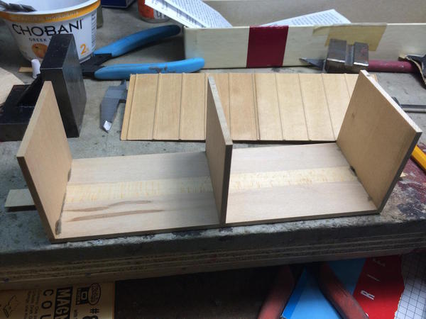

The decals are Walther's and are really old, so just to be sure I coated them with Microsol liquid decal film which restores old decals and keeps them from cracking. I don't anticipate this being a long project. Famous last words...
I weighed the parts along with the trucks and the white metal fittings and it comes out just about 15 ozs. This is right on target for NMRA's car weight for a 40' freight car in O'scale, so no additional weight should be needed. I intend to weather this car. I haven't yet gotten the courage to weather my store-bought cars and engines, but I don't have that reservation with kits and scratch-build projects. I have Kadee couplers for it too. One the first two kits, I only put Kadees on one end and big, fat, O'gauge monsters on the other so they would mate to the rest of the train. On this car, I may put Kadees on both ends. Sometime in the future I plan on converting more of my O'gauge couplers to Kadee. With my wide curves, I can get away with much closer (more scale) coupling.
Attachments
Thanks, but I've got this one covered. I went on the Google and looked for images of Redi-kilowatt, Philadelphia Electric, Pennsylvania Power and Light, and Louisville Gas and Electric. Since I'm going to build a Bourbon distillery at some point, I chose LG&E. I also doctored up an image with Redi-kilowatt to make another sign.
I'll cobble together some backing and supports and make some signs for the substation. I'm finding for some simple graphics I'm able to get by using Apple's "Keynote" app that's a clone of PowerPoint.
I've already received the money from PayPal for the Santa Fe F3 A-B-B-A that I sold through eBay. The sale closed on the 20th and the money's transferred to my bank tonight. Pretty fast turnaround. Now I have to decide what to do with the money... more buildings? A new loco to replace the Santa Fes? MTH DCS? Some combination of these? I have a budget for the trains per year that's been arranged with my better half, but anything I can do to contribute to it is highly appreciated. I don't change the budget even if I get additional funds. It just reduces the $$$ needed from the family funds.
In looking at the layout tonight, my grandson and daughter think I should start filling in the back right corner where the mountain's going to go. Some of proceeds could go to buying more materials and four tunnel portals.
I like the sign very much! It conveys the message and is the right era!


