I recently installed the CCM into my Lionel 6-28028 Allegheny (TMCC). This engine uses a IR wireless tether.
Identified two wire cable from IR tether and unplugged from motherboard.
Used ohm meter to identify which wire was the serial data - in my case it was an orange wire.
Cut orange wire near CCM location. Used the connector that came with CCM that had two wires preinstalled to pin 1 and pin 2. Slid heat shrink tubing on both ends of the cut orange wire to insulate solder connections.
Soldered the wire from pin 1 of the CCM connector to the end of the orange wire coming from the motherboard.
Soldered the wire from pin 2 of the CCM connector to the end of the orange wire going to the IR tether.
Slid heatshrink tubing to cover the solder joints, but did not heat - wait until testing done.
Plugged IR tether two wire cable back into mother board.
Tested with cab still off - speed control worked, but no TMCC controlled sounds from tender.
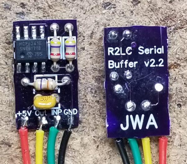
Used scope and found that serial data to CCM Pin 1 was 5 volt pulse, whereas serial data from CCM Pin 2 to IR tether was only 1volt pulse. CCM serial data buffer not powerful enough to drive my IR tether. Had to buy a three wire buffer that went between CCM Pin 2 and IR tether, and required a connection to the +5VDC on the R2LC. Did so, using heat shrink tubing just slipped on.
Test was Okay - so heated shrink tubing, dressed wiring, put engine back together.
All works great!!!
BTW - the three wire buffer had its own heat shrink installed so could not exactly determine what it was, but I am sure it is a transistor and a resistor or two. I was also told that a couple people who had a similar situation were able to make it work using a 33K resistor connected to the serial data output of CCM Pin 2 to +5VDC of the R2LC