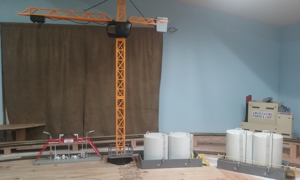
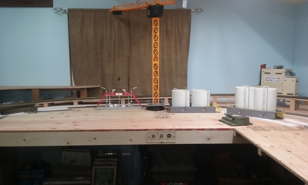
Hi all, i picked up a DC crane and got rid of the battery pack and the controller was busted. My plan is to use sp/st mini momentary switch. But I need help wiring it up as I am slow as dirt on electrical ! LOL.
Replies sorted oldest to newest
Hi Mike. We need some more info. How many batteries and how were they configured? Does it only run the hook, or are there other motions? Do you have a DC supply?
John H posted:Hi Mike. We need some more info. How many batteries and how were they configured? Does it only run the hook, or are there other motions? Do you have a DC supply?
Hi John, first off thanks for answering! It has 3 funcrions, swing L & R, hook up and down, and hook in and out on the boom.
It had 6 AA batteries in it, i found a wall wart the powers it great. The thing is if I touch both wire for a single function it will work and if I reverse the wire it works the other way just like I want.
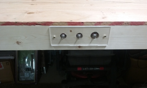
I just don't know how to wire to a switch, i plan on using 3 switches one for each function.
I hope this helps!
Hi Joe, i do have some DP/DT switches! If nobody else replies I will give that a try! I think John it typing as I am responding to you!
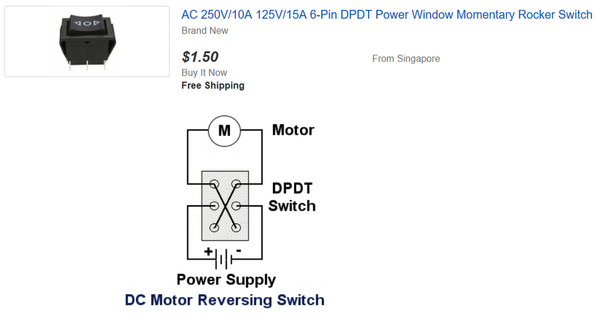
Your switches should have six terminals. Run the motor wires to the center two. Run your power leads to the top two, noting + and - . Run a jumper from + to the opposite terminal on the bottom, and do the same with the - to the opposite side on the bottom. If + is on the right on top, jumper goes to the left on the bottom. Try that on one function. Hopefully it will work, and you can repeat for the other two switches. Someone more talented than me can maybe put this in a nice diagram for you.
Thanks John, I think I got it! I will let you and Joe know how it turns out!![]()
Presumably your DPDT switches are of the momentary 3-position center-off, style? Also referred to as (ON)-OFF-(ON). This would be like the window up/down rocker in a car with power windows. The idle position is center-off with no power applied to the motor.
The "classic" wiring is as John H describes. The 6 terminals of the DPDT switch will be in a 2 x 3 grid like the diagram
Attachments
Dpdt works to reverse polarity Mike. ON/ON or ON/OFF/ON doesn't really matter if you choose The rest of the circuit to fit it.
Look at the lugs as two rows running parallel to the handle, a left and right.
Lets say the two L&R center posts get the ower input, +red&-blk. (in or out or, + to L or R doesn't really matter)
Now the corners get tied corner to corner by 2 jumper wires. It looks
like --X-- now
Pigtail off the X leads to go to the motor.
Top dashes get input, bottom dashes to motor → _-_-_-X-_-_-_
OR use the two as a feed to 3 other buttons assigned to each of the 3 motors.
I.e.
1-3 on/on dpth for direction, 3 other spst momentary on for best actuation.
OR
3 3-position dptdt on/off/on "momentary" (note: ON/OFF/on on/OFF/on ON/OFF/ON are different when you order.. #1 stays on in one dirrection, #2 is momentary both directions, and #3 is standard 3 position.)
or a dpth a rotory and button... etc. etc.
Stan, thanks for the picture. It will help a lot.
Mike, the picture has the configuration different, but it accomplishes the same thing.
Thanks Stan ! John is right , it sure is going to make things easier for me! You guys rock and make life so much easier for us slow folks like me!![]()
Thanks again everyone!![]()
I only get up at 5 when I'm planting corn.![]()
![]()
![]() Mike!
Mike!
Lol John, i get up anywhere between 3:30 & 5 AM. Depending what time my English Bulldog TANK wants to get up! But I am also in be by 8!


