The product description at the Plastruct website states ... "Prior scratch building experience recommended."


A search of our forum found no particular info, but people have mentioned minor problems even working with their plain plastic sheets, etc.


I've never done any "scratch building." Just kitbashing, detailing, etc of regular plastic kits. Is this Plastruct kit a real big project? We are about to buy two of the kits, as we are going headstrong into modeling Conrail's Chemical Coast Secondary in NJ.


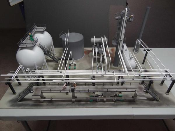
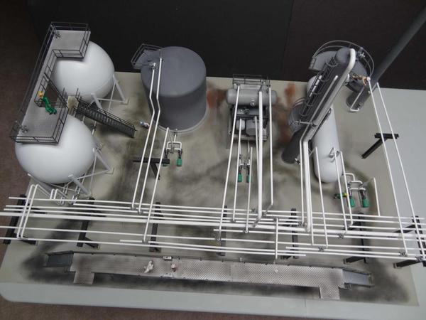
I see forum member CBG did a wonderful job of building the kit (as evidenced by the below photos I included), but he lists no email that I could use to bug him. Lol.


Thanks for any info/experiences you may have.

Jim Ledet


refinery1

refinery2

Attachments

Images (2)
  • refinery1
  • refinery2
Last edited by CNJ Jim
Original Post

Replies sorted oldest to newest

I built this kit a few years ago. unless they've changed the instructions and provided better pictures, I'd agree that it is a difficult build. the tanks and platforms are relatively straightforward, but the pipe connections, etc. are hard as the pictures are blurry and the directions nil. after awhile, I gave up on the instructions and just connected pipes as I thought made some visual sense. If a prototype was built duplicating my model, I wouldn't want any real oil to flow through through it That said, when finished, it's an impressive model and makes a nice statement on the layout and the basis of a good diorama. The pictures you posted should help enormously and if you're familiar with refineries, that's a good thing, too.

jerrman

Hi Jim,

When I looked at the photos the first thought that came to mind was "Where do all of the pipes on the rack go?".

The answer seemed to be two tank farms, one for crude and the other for product. So, what goes where?

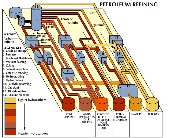
A search of PETRO CHEMICAL REFINERY PROCESS DIAGRAM produced these results. Perhaps one will resemble the refinery pieces and lead you to the piping diagram. there are many-hope that helps.


62965-004-1C43716A

Attachments

Images (1)
  • 62965-004-1C43716A

I have a lot of scratchbuilding experience in a variety of hobby areas: model ships, trains of various scales, model cars.  I don't recall any special problems with plastruk. Looking at the refinery, the only problem I would anticipate is that sometime, bending the 90 degree angles needed in smaller pipes can cause them to break.  The stuff is easy to cut, easy to glue (I use plastruk glue, too), and easy to prime (I always do) and paint.


This is no substitute for experience, and no experience unless you try, so why not jump into it after putting some thought into the plan, etc.  Myabe the first attempt will not be entirely to your liking - but probably with a little work and refinement, it will be . . . 

Last edited by Lee Willis

I built my refinery about 18 year's ago it had all the elbow ,tee and other thing you need to build it ,it didn't have any pictures only drawings, I have did a few kits from them , it helps if you know how to read blueprint or drawings because that is what they send you to build it from , they are like the one's that they build them from it was easer for me because I'm in the building trade , it has a lot of small parts and it take some time to do good luck ,please excuse the dust I put it there and haven't did anything with that corner yet work in progress . 


Guy 

PIC_0895

PIC_0896

PIC_0897

PIC_0898

PIC_0899

PIC_0900

PIC_0901

PIC_0902

PIC_0903

PIC_0904

Attachments

Images (10)
  • PIC_0895
  • PIC_0896
  • PIC_0897
  • PIC_0898
  • PIC_0899
  • PIC_0900
  • PIC_0901
  • PIC_0902
  • PIC_0903
  • PIC_0904

I just got in one of those periodic mail-outs from from Walther's that has this kit

on sale for $180 (down from $200).  If you've done kitbashing, that should be

sufficient.  Too bad about the bad plans, as people are stating.  I don't  need another

real estate eater, but Wigville's above looks interesting for a defunct regional oil

company as I would model.

Jim:

I am starting a refinery build for a customer in HO scale that incorporates the Plastruct refinery kit so I am looking at the various instructions and drawings as I write.


There are two drawings. One shows the structures and one shows the pipe routing; hopefully your kit has these. Mine are marked PL8A and PL8B. View the pipe routing as an electrical wiring diagram. Circles drawn where pipes meet means they need to be connected. Otherwise the pipes are simply crossing over or under each other.


At both ends of the elevated pipe way where the pipes simply end - just cap them. Whether they are supposed to go somewhere else off diagram I am not sure. Alan Graziano will know better since I believe he helped Plastruct design this kit.


The kit represents a small part of a refinery (production of methanol and propylene).

On the right side are the structures to produce methanol and propylene. You have a distillation tower, dryer, condensers, chillers and a reflux drum.

On the left side the spherical tanks hold the propylene under pressure. The vertical tank holds the methanol.

There are no crude oil storage tanks to start the process. If you have not already purchased maybe instead of two petrochemical kits or in addition to them purchase some storage tanks for crude to start the process. The crude storage tank usually connects to a desalting tank first then to a furnace to heat the crude to temp then to the first distillation tower. Since the desalting tank and furnace are not made by Plastruct you can purchase kit 3027 or kit 3015 for crude storage and connect to the distillation tower (the floating top tank is usually for product not crude but it looks good on a layout).

If you buy two of the refinery kits you can designate the other set of spherical tanks for LNG/propane or another product that needs to be stored under pressure and the vertical tank for another fuel like diesel or jet fuel. You could probably set up the second reflux drum as a desalting tank and the second demethanizer as an alkylation unit to make propane or butane. build up the base for the second dryer and you can make it a furnace. This way you have a crude storage tank feeding a desalting tank then a furnace which you can connect to both distillation towers to start the refining process.

Bottom line with two kits you can have four products - propylene (ie propene), propane/LNG, methanol and a fuel like diesel or jet.


Pipe routing for the kit (simple version) appears to be:

Demethanizer outputs to methanol tank

Dryer outputs to methanol tank

Demethanizer outputs to propylene tanks

The reflux drum appears to output to the propylene tanks through some pumps (Alan can verify this) 

All other piping is input/output between the distillation tower, methanizer, drum and dyer. Best place to start pipe routing is at the distillation tower since it is the start of the process.

Good luck

Joe


Thanks Charlie - Jim will at least have two. I don't believe anyone makes a kit for distillation towers in O scale so a third one would need to be scratched built. Jim could make a list of the parts in the kit needed to build the tower and purchase these separately from Plastruct. 

On the advertising side Alan or myself would be more than happy to build Jim one!

Charlie:

You sound like you worked in a refinery - **** you are wearing a cowboy hat in south Jersey so to a guy who lives in Arizona you can't be all bad!

I build O scale refineries as part of my business. With your permission I would like to send you a copy of 'my' process flow that I follow for you comments/corrections. 

Thanks

Joe


Joe

I have been retired 18 years and worked in polymer plants like Polystyrene and Poly propylene, so my memory on all the details is not that sharp.

There is only 2 separation required in the propylene unit. But the propylene/propane separation requires so many trays that two columns are used to maintain a reasonable height. The third tower is the ethylene tower.


The cowboy hat is from my cowboy action shooting days with SASS.

SASS now headquarters at their ranch in New Mexico, where they hold the World Championship http://www.sassnet.com/EoT/

Last edited by pennsyk4

Alan

The piping runs in your oil refinery look very realistic.

What really stands out are the support structure, access platforms and the many strategically placed ladders. A degree of congestion found in most refineries.

Just a terrific job and certainly a point of interest on your railroad.

You need a fleet of tank cars

Originally Posted by Trainman2001:

Good to read this thread since I'm planning on putting that Chemical refinery on my layout. I'm not afraid of the building, but I was concerned about the kit's completeness. I built their Truss bridges inverted which meant basically using their structural parts and designing my own plans. I suspect that in the space I was to use, I'll have to do the same thing.

Might want to consider a Chemical Plant. Most Chemical plants have most their operating equipment under structures with one end open, depending on the end product, some do have a tower. Feed tanks, and product storage silos. As to furnaces, (usually boilers are used to produce steam from 400# downward for heating, and keeping piping, and tanks heated), furnaces are usually used to burn off unwanted products and gases, boilers would be downrange in the utility area. Most refineries are located near a waterway. Chance for tugs and barges.

A lot of piping seen in pics, etc. actually may carry, steam, cooling water, waste, gas(s), bottoms, heating mediums, etc. besides product.

Another good use of tanks, are at terminals. All 3 are great opportunities for lots of switching.

Worked 30 years for Chemical/Refinery. Ended my years as a consultant for shutdown/ turn-a-round of Chemical and refineries. Great jobs, great memories.

Should add. See some great modeling of refineries here. Even some in-plant training models weren't as good, or as detailed as some seen here. Great job guys.

Last edited by josef

It's great to have forum members who have actual operating experience on the things we want to replicate on our railroads. I spent many years as a training manager in a petro/chemical company and had the fun of being in all of those plants many times. The most interesting chemical plants were the ones making propylene oxide. It had two flare stacks that were several hundred feet high. They had one purpose; burn off the entire un-reacted in process chemicals. This intermediate product, a peroxide was explosive if it's concentration exceeded a specific level. The quantities in the plant were sufficient to do catastrophic damage to the plant and surrounding communities. If the reaction were to cease for some reason, this in-between chemical was sent to these enormous flares and burned. The resulting flame was a hundred feet high and lit up the countryside if it occurred at night. So unlike the description that Josef gave, none of this plants operating units were under cover. 


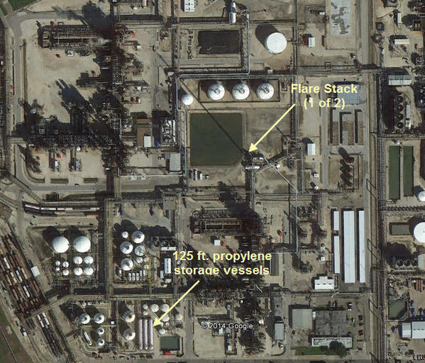
Just for fun, I located this plant on Google. The last time I was there was 1985, but it hasn't changed much and is still in business.


I've pointed out two landmarks. Those monster flare stacks. I don't know the actual height, but the stack's shadow is almost 600 feet long. And the three propylene storage vessels which are each 125 feet long. Every thing about that operation was interesting. At one place, they inject pure oxygen into prolylene at two bunkered mixing stations. They oxygenate it past the flammability point, but at one point, it passes through this zone, thus the reason for the bunkers.

 Bayport Plant

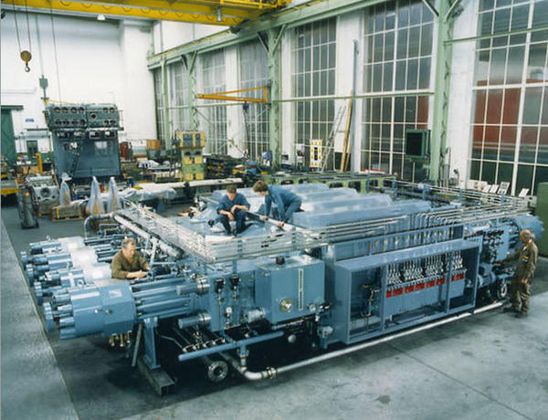
In another plant in Port Arthur, they made low-density polyethylene using 50,000 psi hyper compressors. These massive machines were housed under cover in open-sided sheds and were driven by 5,000 hp synchronous motors. I don't know if this process is still in use. .


I wasn't sure if this process was still being used, since They couldn't make linear low-density polyethylene by this process and of which trash bags are made. So I did a little research, and not only are they still be used, they're still being manufactured and have gotten larger. They now have more cylinders and up to 36,000 hp electric motor drive. That's not a typo!


Hyper-Compressor


The mechanical loads and pressures on these machines are so severe that misalignment can mean bad things. They use tungsten carbide plungers that are about four inches in diameter. They can handle the pressure loads, but aren't happy with any side thrust. I wrote a training course on aligning these beasts.


Sorry about taking this thread in all these strange directions, but these plants can be fascinating places. I really do want to build that chemical plant.

Attachments

Images (2)
  • Hyper-Compressor
  • Bayport Plant

Just wanted to say thanks to all! Lots of good info and experiences here.


And, of course, the professional quality models shown here and elsewhere on the forum are spectacular. I love just studying the photos.


My train buddy and I are now very excited about this refinery project. Eager to get into this "scratch building" .... a good way to spend some of these hot and humid NJ summer evenings in his air conditioned basement. We ordered two refinery kits, two spherical tanks, and a tall tank set from Walthers to start with. Will order tubing, etc from Plastruct when we know the sizes. Also ordered a hardcopy of Plastruct's catalog to make life easier.


I grew up and worked in Linden, where this Bayway refinery is located. Chemical plants, too ... yet I was never interested in that area of model railroading. It was always coal for me. (Maybe because my home town was often mocked because of the "pollution?"   )


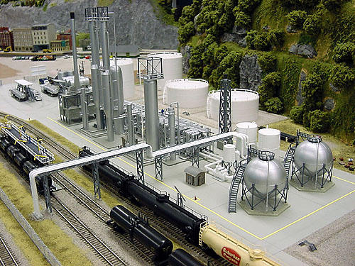
The footprint of our refinery will need to be relatively small, but we would really enjoying learning, and making it a bit technically correct. And, switching is important. Maybe the footprint of the below pictured refinery the Midwestpioneer modeling club .... Club .... built in N. Scaling up, it seems to be approx 11 ft on the longer side.


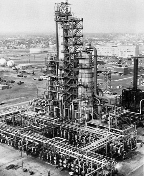
Below that is an 1969 photo of the Bayway's "cracking unit." That would be intricate to model! 


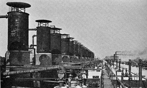
Or, maybe model the Bayway refinery as it looked in 1909, when Mr Rockefeller built it?    (third photo)


refinery_overall2

Standard_Oil_Cracking_Unit_1969_for_web

Standard_Oil_Refinery_Linden_1909_for_web

Attachments

Images (3)
  • refinery_overall2
  • Standard_Oil_Cracking_Unit_1969_for_web
  • Standard_Oil_Refinery_Linden_1909_for_web
Last edited by CNJ Jim

Jim:

You are buying two of the refinery kits plus two more spherical tanks. That is six spherical tanks total. Is this on purpose? If not then instead of the two spherical tanks you may want to consider two of the floating top tanks or even some of the horizontal tanks (propylene storage vessels Trainman discussed). The kits contain only one vertical storage tank for product and no crude storage tanks at all.


For all:

Attached is a flow diagram I put together to help me build refineries. If anyone sees any errors please holler out to me.


Attachments

Jim,

If it is going to be modeled after New Jersey, you have to have me construct it LOL.

I have built the Plastruct Refinery kit a number of times. The kit is not easy to construct and the directions are not great. It is actually a chemical unit more that a refining one. I can build whatever you want or finish the kit for you, and I am sure some of the forumites will back me up.


Alan Graziano

Post

OGR Publishing, Inc., 1310 Eastside Centre Ct, Suite 6, Mountain Home, AR 72653
800-980-OGRR (6477)
www.ogaugerr.com

×
×
×
×
Link copied to your clipboard.
×
×