


I still have about 20 blank boards.
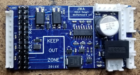
Here is the "final" fully assembled product. Other than a couple of crooked components, it's as intended. I noticed when looking at the picture that the 680uf cap was not straight. ![]()
Attachments
Images (1)

Very nice John, looks good to my eye! ![]() I would sure take about 6 of your blank boards, except for the shipping business.
I would sure take about 6 of your blank boards, except for the shipping business.
I will check out jlcpcb and allpcb and see what those options look like. Thanks for the update!
Rod
John, how do I contact you to get some bare boards? Two boards would suffice for me.
John, are your trace widths based on 2 oz or 4 oz copper thickness?
Rod
@penn station posted:John, how do I contact you to get some bare boards? Two boards would suffice for me.
Same as always, my profile email. ![]()
@Rod Stewart posted:John, are your trace widths based on 2 oz or 4 oz copper thickness?
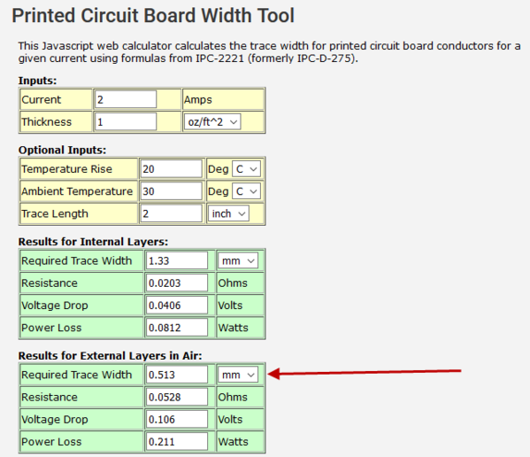
They're standard 1oz copper. I use a trace width calculator to verify the current carrying capacity. The heaviest current is the input power, that's at most a couple of amps if you have a smoke unit running off the R2LC. The 2oz copper tripled the cost of the boards, I didn't see the need. The power carrying traces are shorter than 2" and are .508mm in width.
Attachments
Images (1)

Thanks for that clarification John! ![]()
Rod
So, Did you ever determine the price point per board per quantity. If in fact you had these built...Maybe we can get you over the border..
In quantities of 100 or less, the total costs for parts & assembly are around $30-35. Recent shipments have also encountered a 25% tariff, adding to the pain. It will also take more work to get them ready for assembly, documentation like assembly drawings, detailed BOM lists, etc. have to be created. Given the response, I just don't see that happening, and I can't really afford to be stuck with several thousand dollars worth of fancy motherboards.
I posted all the files necessary to recreate the boards in the first post of this thread. I got a batch of blank boards, and I'm keeping some for my use and selling the rest of them. It was an interesting exercise, and I'll be able to use the ones I've built in upcoming projects.
GRJ... On the smart mother board.....D2 next to the track power plug, which direction does the cathode band go? Other locations have a dot which I would think means cathode. Your pictorial on page two seems to show cathode band to the left. Is that correct?
Richard
I think there is a market for $35 completed product. I would buy several . I don't think that this forum is an accurate market survey as I just ran into this post. I think that the initial discussion probably lost many including myself.
@Rppoind posted:GRJ... On the smart mother board.....D2 next to the track power plug, which direction does the cathode band go? Other locations have a dot which I would think means cathode. Your pictorial on page two seems to show cathode band to the left. Is that correct?
Richard
The cathode (this is the LED), has a little T on the back, that points toward the power plug. That dot on the silkscreen was inadvertently missed.
@Art Lites posted:I think there is a market for $35 completed product. I would buy several . I don't think that this forum is an accurate market survey as I just ran into this post. I think that the initial discussion probably lost many including myself.
At $35 I might break even, so that's pretty much a non-starter for me. The problem here is when the Chinese make some little board like this, they make 50,000 or more of them, and that brings the cost per unit way down. Making 100 or so is a whole different ballgame. Stuff I buy for a buck or two from China I couldn't make for $10.
Many thanks GRJ,,,little T pointing to track power plug it is for D2. Last thing I want to do is solder the LED on backwards.
Richard
GRJ.......Finally got my 1st motherboard assembled and inspected. I plan to start with no R2LC and connections. If red LED lights and no smoke I'll add a R2LC and a coupler and move on from there. Question on LEDS. I see several resistors on your led bench test perf board. Does your motherboard need the same 470 ohm resistor as standard TMCC? Does it need a diode for conventional? Thanks for all your work on this project.
Richard
Yep, the requirements are the same as any other TMCC device using the R2LC, the lighting outputs come directly from the R2LC. You don't need the .01uf load caps for LED lighting as I put those in the board design for the lighting and smoke outputs.
Still have a handful of the blank boards if anyone is interested...
GRJ....I remember you wrote that the Smart Mother Board would drive a ERR sound Commander from the
"sound" EH connector. Will that connector also drive a Lionel TMCC sound Mother Board? I am trying a 691-MB00-15C loaded with a RS 4 power supply and Sound card. It is a two port sound only board. Lights and couplers are working. R2LC feature set to 4. All i'm getting is engine idle. Several times on power up I get a coupler air release when I press uncouple. Next coupler command it opens but no air release. I have the serial line on pins four on the SMB and the sound board per my pinout for this board. Any idea what I'm missing?
Richard
It's a bog stock serial data output, so it should drive any TMCC sound board. The 4-pin sound connection on the smart MB is identical in pinout as the ERR boards, so the cable that comes with the sound boards should drop in and play. It does for me. I honestly don't know what you're missing, it should be dirt simple.
Thanks John...I'll take a day off from this and do some yard work. Wednesday get all the doc's out and look at everything.
I'll hook a DCDR and ACDR and confirm that is working. To be honest I was ready for the first SMB to be inop. That puts me ahead of the game.
Richard
Hi John; I have finally ordered a few of these boards from OSH Park, and I'm just getting set to order up the parts that I don't have in stock. Just curious; do you have any kind of ready available list of digikey PN's from the parts BOM that you ordered for your builds? That would certainly make ordering easier, especially for a lazy type such as myself. ![]()
Thanks, Rod
Add Reply
Sign In To Reply
