@Laker80 posted:

So cut the pins and secure the two track ends together?

No, if you must cut to fit; choose to cut the non-pin end first. Then you don't have to play around with the pin side.  

Pins doBdo makeemake it easierieasier you had no pins, screws can be made to hold them in alignment.  ≤ Real nice "spellwreck" program google has, eh? 

Pins do make it easier, but screws are enough to hold an alignment.

 There is a table of "FT combos  to = (?) X inch " floating around here in some older SCARM posts. Might be worth a hunt.

@Adriatic posted:

No, if you must cut to fit; choose to cut the non-pin end first. Then you don't have to play around with the pin side.  

Pins doBdo makeemake it easierieasier you had no pins, screws can be made to hold them in alignment.  ≤ Real nice "spellwreck" program google has, eh? 

Pins do make it easier, but screws are enough to hold an alignment.

 There is a table of "FT combos  to = (?) X inch " floating around here in some older SCARM posts. Might be worth a hunt.

What would you use to cut the fastrack rail bed? Coping saw? Score it with an exacto knife and then try cutting? I think I have all but one area in my plan figured out to avoid modifying the track. 


Attachments

Files (1)
That bottom section looks to be a little off.

If you need to cut the roadbed, a coping saw would probably work.  I used a hobby hand saw like the ones in the links.  They come in handy for all sorts of things.  Mine is X-Acto brand.  This is an advertisement from Michaels, but you can get them lots of places.

 https://www.michaels.com/x-act...aw-set/10223584.html

Here are a couple others that Micro-Mark has for sale.

 https://www.micromark.com/4-in-1-Zona-Saw-Set

 https://www.micromark.com/10-p...-Razor-Saw-Knife-Set

About track pins.  I did this once, and it worked.  I pried the pins lose from the end to be discarded with a flat blade screwdriver.  Then after a light touch with a fine tooth file on the cut end, I put the pins in the appropriate rails and cinched then down with a rather robust pliers.  It worked for me.  Someone else may have a better idea.

Does anyone have a good guide or video on how to disconnect and reconnect the wires from a switch? It looks like you would remove them from the track side and use an eyeglass or computer screw driver to reattach them but I don't want to do this without confirming.

I'm looking to remove the wires, drill a hole through the table, fish the wire back through and have them hidden. 

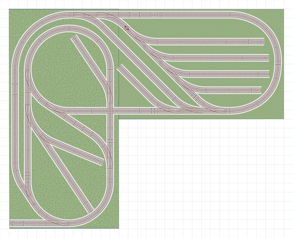
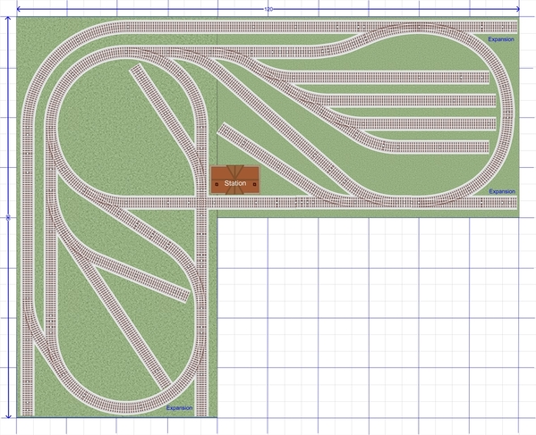
I liked Burkus' design on the first page, I have done many designs with similar features and posted on the forum, but not a 8x10.  Constructed with a 4x8 and 4x6.  I worked with his design and eliminated the reverse curves, and then added a run-around track spanning the yard.
M810V1a

I also added a few industry spurs.  One can do without the run-around track for longer yard spurs if desired.  Delete some industry spurs if it looks too busy.

Attachments

Images (1)
  • M810V1a
Last edited by Ken-Oscale

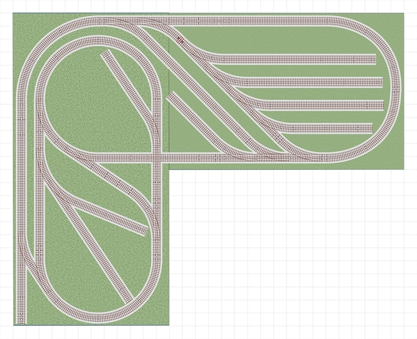
You might wonder why I mixed O48 and O36 on the right-hand side of the layout.   I use a tight tolerance of 3/32" in my layouts, this one connects about 1/16".   I could not find a perfect connection with just O36 curves, but the O48 additions changed the geometry so I could find a match.

M810V2a

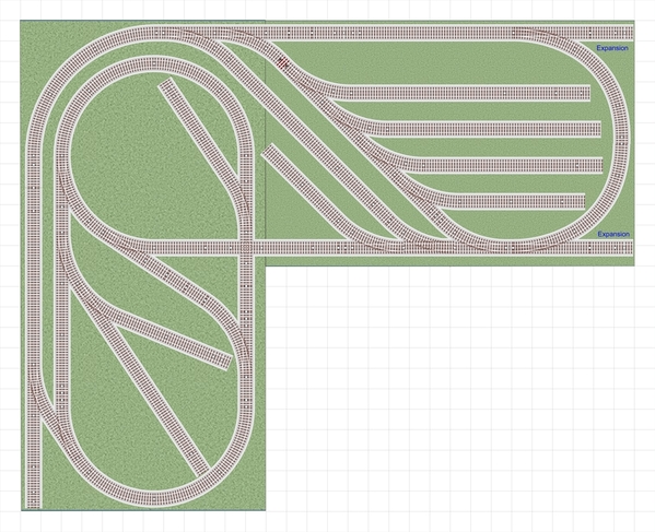
One could also expand off the bottom left 4x8 board.

I use a lot of trial-and-error (which can be time-consuming) in assembling my layout designs.  AnyRail (free for up to 50 sections of track) is easy for me to move sections around and try different configurations.

Fastrack can be cut to build custom-length sections, but its not fun, and hard to get great results.   So I avoid it in my designs, which means I have to often use lots of small sections to get the right length.  And do the technique mention mixing different diameter curves.

Attachments

Images (1)
  • M810V2a
Last edited by Ken-Oscale
@Laker80 posted:

Does anyone have a good guide or video on how to disconnect and reconnect the wires from a switch? It looks like you would remove them from the track side and use an eyeglass or computer screw driver to reattach them but I don't want to do this without confirming.

I'm looking to remove the wires, drill a hole through the table, fish the wire back through and have them hidden. 

Laker, You are talking about Fastrak switches, I think.  Yes indeed, just use a small screwdriver as you mentioned.  If you don't have the wiring diagram, just write down which color goes on which connector or as my older son-in-law pointed out to me, take a photograph of it before taking it apart.  These young folks teach me new things all the time.  I can be pretty slow.  Make sure none of the strands of a wire come loose and bridge to the next connector when reconnecting.  I only did it once on Fastrak switches, and it was a few years ago.  As long as there is no power on any of the wires or track, you can do that with any device as long as you carefully record before taking it apart.

@Laker80 posted:

Does anyone have a good guide or video on how to disconnect and reconnect the wires from a switch? It looks like you would remove them from the track side and use an eyeglass or computer screw driver to reattach them but I don't want to do this without confirming.

I'm looking to remove the wires, drill a hole through the table, fish the wire back through and have them hidden. 

You can do it either way. Personally, I prefer unscrewing the wire at the controller end, but that's just me. I take the controller apart and unscrew the wires, making sure to write down which color goes where. I then drill a hole through the layout directly under the switch and run the wire through the hole and connect back up to the controller. 

Also, if you need more length for your wire, use 4 conductor telephone cable to extend the wire. In that situation, I do not remove the wire from either the switch or the controller. I simply cut the wire in half and feed the cut end still connected to the switch through the layout hole, so now you have two cut ends under the layout - one from the switch and one from the controller.  I then cut the length of new cable I need to make the two cut ends connect together and twist the colored wires together at both ends using "jelly bean" connectors. 

Add Reply

Post
The Track Planning and Layout Design Forum is sponsored by

AN OGR FORUM CHARTER SPONSOR

OGR Publishing, Inc., 1310 Eastside Centre Ct, Suite 6, Mountain Home, AR 72653
800-980-OGRR (6477)
www.ogaugerr.com

×
×
×
×
Link copied to your clipboard.
×
×