I’m ready to install fuses on my O gauge layout Am I right to assume that they go on the bus lines A, B, C, & D, but not the common bus line (U)? on my ZW. I’m using 3 terminals for trains.
Original Post


|
|
I’m ready to install fuses on my O gauge layout Am I right to assume that they go on the bus lines A, B, C, & D, but not the common bus line (U)? on my ZW. I’m using 3 terminals for trains.
Replies sorted oldest to newest
@Don Baird posted:I’m ready to install fuses on my O gauge layout Am I right to assume that they go on the bus lines A, B, C, & D, but not the common bus line (U)? on my ZW. I’m using 3 terminals for trains.
Correct. You may also want to see basic circuit protection at "Circuit Protection for Toy Trains".
That's where I shared my protection on a very large layout.
I still don't understand the fascination with fused ZW outputs. The transient voltage spikes zip right through and around those, and when you're out of fuses, no more train play.
Fuses and TVS protection diodes perform two very different functions. I like Susan's idea of using PTC's in place of fuses, but you still need to add the 1500W 33.3V TVS at Digikey for transient voltage spikes.
Susan's diagrams are very helpful for an electronics novice. John, where would I add the TVS?
Thanks
Add the TVS at the track connection for each transformer output. It goes directly across the power like you're trying to short it out.

Where would I be able to buy some of these electronics parts?
Don, actually, installing a fuse in the common would provide better protection for the ancient PW Type Z/Zw transformer, as you can limit the current draw to 10 amps. Do note that all U terminals are connected internally, so you can use one as common for all circuits. Having said that, the terminals are riveted to a common internal buss, and over the decades these connections may have deteriorated.
I also recommend using breakers rather than fuses. The latter cost to much, as they'll blow on every derailment. In a recent thread GRJ has piinted to a source for magnetic breakers. I currentlyuse thermal breakers, which are slower and cheaper, but am considering whether to switch to the magnetics GRJ recommends..
@Trainfamily posted:Where would I be able to buy some of these electronics parts?

RJR, this string is very confusing to me, but your comment seems to be at my level. Let me tell you where I’m coming from
in a previous chain I posted questions about my Christmas trains - two trains circling the tree on two circles of fastrack powered by my ZW. One of the power lines and the carpet melted presumably because of my grand children’s derailments. I replaced the badly worn power lines with 16 gauge for the remainder of the season I also decided to add some precautions to the permanent layout I’m building using tubular track, my ZW, and and a 1032.
So, I decided some kind of fuses or circuit breaker. Your answer to my question was unexpected and simple if I understand it. Put a circuit breaker on the common bus - U on the ZW. I had assumed it would be a 10 amp breaker on terminals A, B, & D for the three trains and a lower amp breaker for C. Tell me if there’s anything right about that.
with the 1032 I am using variable power terminals U & B for the trolley. (U to the center rail). Fixed power from B & C powers some accessories on the trolley lines and is converted to DC for a timer relay to control the stops & starts on the trolley line.
where do the circuit breakers go?
How do you know if the TVS at one of the lock-ons or below at input to terminal strip does its job and absorbs the transient voltage spike? It protects the locomotive electronics but kills itself but is it obvious so you know when to replace?
@SteveMa posted:How do you know if the TVS...
They are not one-time devices, they are continuously clamping transients. A TVS usually fails shorted, so it will be very obvious if it fails.
A TVS has a very long life unless it's subjected to a spike that exceeds it's maximum rating. They're quite different than an MOV, those degrade with ever surge they absorb. FYI, the MOV is what is used in most "surge protection outlet strips".
Thanks. Getting close to the comfortable zone with your help
Don, I'll answer your last question first. Breakers and fuses should always be on the transformer outputs, so they protect everything downstream.
A fuse or breaker in the U circuit has one purpose, to protect the transformer. A postwar ZW shouldn't be subject to more than 10 amps. FYI, the ZW internal breaker is in the U circuit, but is very slow acting. It provides no protection if there is a short between any of the ABCorD outputs, which is possible.
A current of less than 10 amps can cause considerable heating on the layout. Breakers or fuses should also be put in each of the output circuits to protect the layout. They should have the lowest amp rating that will operate your trains, which is usually less than 10 amps. On my layout, I run 6 TIU channels. Some channels control areas where probably not more than 1 or occasionally 2 trains will be moving at once, such as yards. These get 5 amp breakers. Mainlines where I might have 3 locos running get 7.5 amps. But I do not turn smoke on.
No fuse or thermal breaker opens immediately upon the current being exceeded. There is a lag while the thermal elements heat up. By using smaller amperage breakers, they open sooner on a short. In another thread, Gunnrunner John mentioned certain magnetic breakers available from Digikey. Magnetic breakers should open as soon as the rating is exceeded. Electronic breakers, such as in the Lionel PH-180 Powerhouse, also open upon exceeding the rating. I am considering replacing my thermal breakers with magnetics, but have some higher priority matters to deal with.
FYI, I use Blue Sea marine push button breakers, available on-line from Defender Marine. They are in the $5-$6 range and have worked well.
Hope this helps.
RJR
Thanks RJR. I assume it would be the same for the 1032: a breaker for each post in use (U, B, & C).. It’s only running a trolley and some accessories. Low amp breakers?
I don't know what the wattage rating is for that transformer, but I'm sure less than 10 amps is required. For those old transformers: Take the wattage rating; multiply times 0.75; divide the result by the maximum voltage the transformer can put out. The result is the maximum continuous amperage. Ideally, use that as a maximum rating on the U; on the others, that or some lesser capacity depending on the level of protection you want to afford your wiring and devices.
RJR
The 1032 is a 75 watt transformer generating 115 volts. With U as the hot shoe the results are:
AU 5-16 volts variable
BU 0-11 volts variable. Others:
AB 5 volts fixed
BC 11 volts fixed
(C 16 volts ?)
I am using UB Variable to power trolley & BC for conversion to DC timer and to provide auxiliary power to accessories
Your formula: 75 (watts) x .75 = 56.25 divided by (16 or 155 volts) equals 3.5 or 0.4 continuous amperage. Can that possibly be correct?
And even if it is correct, what does that mean for U, B, & C?
Do I even need to worry when all that is connected is a cheap MTH trolley, three 153IRS and a few accessories (crossing signals, station lights)
The transformer has a built in breaker to protect itself.
@Don Baird posted:RJR
The 1032 is a 75 watt transformer generating 115 volts...
The transformer has a built in breaker to protect itself.
The 1032 internal breaker is rated to trip on A-U in 9-35 seconds into .2 ohms , if that will help you.
The breaker on the 1032 is to protect the transformer.
@Don Baird posted:(C 16 volts ?)
A-C is 16 volts fixed. "A" is common on the 1032 and has the breaker in it's feed(except in relation to B), C-U is 11-0 volts(yes, backwards), but like A-B, there is no breaker protection.
3.5 amps would be the max continuous amps, aggregate for the transformer. I don't know where you got the 155 or 0.4 figures. 115 volts is the input from the wall receptacle; it is not something generated by the transformer.
FYI, the 75% continuous rating was given by Lionel itself in its Model Railroading paperback back in the 50's/60s. Also, the breakers in those old postwar transformers were not particularly good. I will leave it to others to comment of the maximum continuous rating for modern transformers.
A handy gadget to have is a cheap AC ammeter. You can ascertain the draw of each device.
Googling, I dug out the section of the Greenberg repair manual covering the 1032, including the schematic. Quite frankly, I can't figure out which combination of terminals are protected by the internal breaker. I'd fuse or breaker all leads
The manual does say the internal breaker when new would open in 7-8 seconds on a dead A-C short, but aging will increase that duration. No mention of protection for other post combinations, such as A-B, B-C, etc. The manual does say that not more than 50 watts should be drawn continuously. This would equate to 0.67 rather than the 0.75 figure I used. But it also says to limit continuous amperage to 4-4.5 amps. If you have much older Lionel equipment, the Greenberg Repair & Operating Manual for Lionel Trains is a worthwhile investment.
Having said all this, in my younger days, back around 1950, I use a Type R (100 watts) to run two locos (#224 & #736), 2 022 switches, and a #97 coal elevator.
Rob, Manual says the breaker is 4 amps
@RJR posted:Quite frankly, I can't figure out which combination of terminals are protected by the internal breaker.
A-B and C-U are not protected by the internal breaker.
@RJR posted:Rob, Manual says the breaker is 4 amps
Manual says the breaker is set to carry 4 amps continuously, but will hold a slight overload when the transformer is cool.
How to test it though is a different procedure. The manual gives an acceptable time - 9-35 seconds into .2 ohms using A-U.
To me, 15 amps for 35 seconds is not acceptable, either from a standpoint of protecting the transformer or of protecting the layout.
This is a bench test, no train equipment was harmed in the testing or development of this procedure by Lionel engineers of the 1940's.
Nevertheless, not acceptable off the bench.
Rob is correct, here's a wiring diagram. Even the combinations protected don't get very good protection with the specs of that breaker.
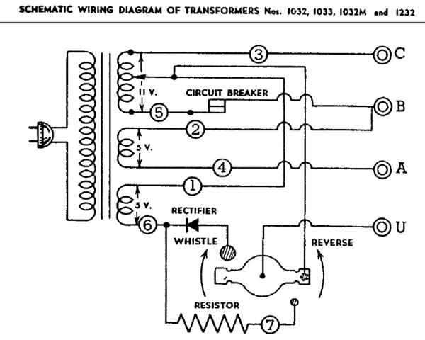

I agree GRJ. If it is acceptable for that breaker to take <35 seconds to open with a 15-amp load, how long would it take when the load slightly exceeds, say, 4.5 amps? I would fuse or breaker every connected terminal for 4 or 5 amps max.
I think TVS has been covered really well lately. 1500W 33.3V TVS at Digikey
So while we're on the subject of fuses and breakers, would anyone like to offer some specific product recommendations for panel mount ultra-fast inline manual reset circuit breakers, such as can be achieved with solid state protection devices in the 5 to 10 Amp range suitable for 10 to 20V AC?
Somewhere on the Forum are recent posts by Gunrunner John about push button reset magnetic breakers, reasonably priced.
@RJR posted:Somewhere on the Forum are recent posts by Gunrunner John about push button reset magnetic breakers, reasonably priced.
Thanks, RJR. A quick internet search of Magnetic breakers on OGR turned up these posted by John:
Sensata-Airpax R11-62-7.50A-B01CV-V 7.5A
Sensata-Airpax R11-2-5.00A-B06CV-V, 5A
Sensata-Airpax R11-2-10.0A-B06CV-V, 10A
https://www.onlinecomponents.c...00aobv-10090622.html
Are these what you're thinking about?
They are definitively less expensive than the PSX-AC and according to that other thread better at lower voltages.
For really fast action, the PSX-AC Circuit Breaker modules are probably the king. THe Airpax Snapak Magnetic Circuit Breakers are very good, but I can't seem to find the fast acting ones without the hydraulic delay anywhere, those are the model you'd like to have.
Here's the Sensata-Airpax Breaker Datasheet, so tantalizing close, yet seemingly unavailable. You used to be able to get the instant trip models from Digikey, but now they only stock the slow ones.
That is them. I'll attach their catalog
I see Steve found the ones I was looking for, those are the fast acting ones.
@gunrunnerjohn posted:I see Steve found the ones I was looking for, those are the fast acting ones.
I just read further into the post and subsequently edited the links before I saw you posted.
What I had before was Sensata / AIRPAX PP11-0-10.0A-OB-V
Which is the faster acting?
Steve, I think the push button variety is easier to mount in a panel. Problem is that if one looks into the catalog where it describes the numbering system, there are a huge number of variations, and no one can stock them all.
Over the years, several forumites have designed various electronic packages for train use, and they or others have packaged component kits which they sold. I wish someone would do that for an electronic breaker such as is found in the PH-180 transformer, the circuit for which has been posted on the forum.
The -0 models are the instant trip models.
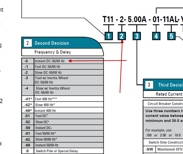

@gunrunnerjohn posted:The -0 models are the instant trip models.
John, Thanks very much for your help. I just ordered 12 of the -0 (instant trip) for the price of 3 PSX-ACs.
@RJR posted:Steve, I think the push button variety is easier to mount in a panel. Problem is that if one looks into the catalog where it describes the numbering system, there are a huge number of variations, and no one can stock them all.
Over the years, several forumites have designed various electronic packages for train use, and they or others have packaged component kits which they sold. I wish someone would do that for an electronic breaker such as is found in the PH-180 transformer, the circuit for which has been posted on the forum.
RJR according to their site there were 29 (push-button panel mount 10A breakers) in stock before my order, so there should be about 17 left. Get em while they're hot.
What site? What breaker number?
Dang it, I forgot to post the link:
Thanks guys.
I just ordered (three) PP11010.0AOBV (the one Steve linked).
John
@gunrunnerjohn posted:Here's the Sensata-Airpax Breaker Datasheet, so tantalizing close, yet seemingly unavailable. You used to be able to get the instant trip models from Digikey, but now they only stock the slow ones.
I actually just picked a set of the 8A version of these up from Mouser to put them through their paces. They only had two and are listed as a non-stock item.
I also picked up a set of these:
https://www.mouser.com/Product...2t12iIyE3HB32g%3D%3D
They are 10A but have very similar specifications.
Its surprising there isn’t at least one variety of the instantaneous trip Sensata/AIRPAX that are normally stocked. They have about a thousand different versions with different actuators, mounting style, and termination. I’d like illuminated rocker switches but had to settle for the push to reset style. Nothing seems to be available in quantity.
Would those 10 amps be good to but on each handle of a z4000?
Thank you gentlemen. Your discussion is fascinating, educational, and sometimes over my head.
Here’s what I’ve decided for the 1032: 5 or 6 amp breaker of some kind for each terminal, U, B, & C
11 is the magic number
C-B is a constant 11 volts (10.9 on my multimeter). U-B is variable: 0-11 I’ll draw a smaller amount than 11, closer to 5 or 6, but it makes sense to me to use the number 11, already in play and the high end of the U-B variation.
Returning to RJR’s formula, 75 x 0.75 = 56.25 divided by 11 = 5.1 amps
Don, you are misapplying my formula. It is for use only to determine the amps which the secondary windings of the transformer, or any portion of them, can carry continuously. An amp is an amp, and has the same heating effect upon a given length of wire, regardless of the voltage being applied. The portion of the secondary windings which is carrying your load will be overheating. Bottom line is that 5 amps is too much for that transformer.
A 5-amp breaker on each terminal may not limit current everywhere in the secondary to 5 amps
@Don Baird posted:Here’s what I’ve decided for the 1032: 5 or 6 amp breaker of some kind for each terminal, U, B, & C
Those breakers will never trip in this application with a 1032.
Shoot! I thot I had it. I’m sorry I misunderstand and mis-applied your formula, RJR, but glad to know.
I’ve spent the last hour watching uTube videos trying to understand this stuff. However, I’m a theologian, not an electrician or even a handyman (as I’ve said, still in electrical kindergarten).
I’m tempted to guess something lower than 5 amps and pray it works! But we theologians know that temptation can be dangerous, and I suspect you all think guessing is dangerous as well. I’m stuck.
It makes me wonder, Bob, do I even need to worry about it “in this application?”
As a theologian, you should know that the quickest way to end temptation is to give right in. ![]()
![]()
I'd try for 4 amp breakers. Does your test meter have an AC amps range? If so, you could check your lighting load and have greater certainty.
If you don't often have derailments with the trolley, chepaest way out would be 4-amp fuses.
Thanks😀
iim in Cincinnati for my grand kids soccer games and track meets. When I get home to Canton I’ll get the meter out. In the meantime I’m “stepping out in faith” and ordering the fastest 4 amp breakers I can find.
My layout is under construction but I can run the appropriate tests.
I am a little Surprised by your recommendation as 4 amps doesn’t seem much lower than five, but thankful nonetheless.
Are you guys saying now that those 10A circuit breakers Steve linked (PP11010.0AOBV) that I ordered yesterday are inadequate? Or am I misreading the comments.
John
@Craftech posted:Are you guys saying now that those 10A circuit breakers Steve linked (PP11010.0AOBV) that I ordered yesterday are inadequate? Or am I misreading the comments.
John
John, whether these 10A breakers are appropriate for your set-up depends on what you plan to connect them to. What transformer to you intend to connect them to and how many trains, accessories, etc will be fed by each circuit at the same time?
@SteveH posted:John, whether these 10A breakers are appropriate for your set-up depends on what you plan to connect them to. What transformer to you intend to connect them to and how many trains, accessories, etc will be fed by each circuit at the same time?
I have a KW to run one conventional Postwar Lionel, or Williams steamer, or Williams GP38on one side.
Other side to run one Bump n Go Trolley or an MTH subway set (which didn't arrive yet).
I use the accessory terminals on the KW, but I have a separate doorbell transformer which I will put into service for accessories.
John
For sizing the breakers for a KW, apply the formula I gave Don (above).. I cannot picture a doorbell transformer having the power to run any accessory.
John, as I understand it the KW is a 190W transformer. Assuming that 190W is input and applying RJR's 75% ouput efficiency calculation, that means it would put out about 143 Watts. If you're running conventionally, lets say that you maybe you don't always run them at full throttle, so at a moderate speed that might be about 12-14 volts. So in a derailment, additional current is drawn from the transformer until it reaches 10 Amps and kicks the breaker. So 14 volts x 10 Amps = 140 Watts, that works. Let's say your Loco is flying along at 18 volts and there's a derailment. This would require 180 theoretical watts being drawn from the transformer for a tiny fraction of a second until the external 10A breaker trips. Can the KW do this? I'll let someone else answer that question. My guess is that a 7 to 8 amp breaker would be a better choice for the KW.
@SteveH posted:John, as I understand it the KW is a 190W transformer. Assuming that 190W is input and applying RJR's 75% ouput efficiency calculation, that means it would put out about 143 Watts. If you're running conventionally, lets say that you maybe you don't always run them at full throttle, so at a moderate speed that might be about 12-14 volts. So in a derailment, additional current is drawn from the transformer until it reaches 10 Amps and kicks the breaker. So 14 volts x 10 Amps = 140 Watts, that works. Let's say your Loco is flying along at 18 volts and there's a derailment. This would require 180 theoretical watts being drawn from the transformer for a tiny fraction of a second until the external 10A breaker trips. Can the KW do this? I'll let someone else answer that question. My guess is that a 7 to 8 amp breaker would be a better choice for the KW.
Instead of putting more thought into it I jumped on the relative bargain and quickly ordered three of the 10A. Live and learn. But I never run any trains at high speed. I don't like the way they look or operate (especially on turnouts). Half way is high for me.
Thanks,
John
SteveH said it. 10 amp is suitable for a postwar ZW (essential) or an MTH Z4000 or Lionel PH-180 (redundant to internal breakers). ABout 7 is right for a KW.
Steve, I do not agree with one part of your analysis. The formula I gave established a maximum continuous amperage through any portion of the secondary windings. If you are running at a lower than full voltage, the wattage being produced by the transformer will be less, but the amperage through the portion of the secondary windings that you have tapped off is determinative. In other words, if you set the voltage at 6 volts and are pulling 15 amps, while that is only 60 watts, a portion of the secondary winding is severely overloaded.
Don, I see Digikey has a 4-amp breaker listed,
@SteveH posted:...180 theoretical watts being drawn from the transformer for a tiny fraction of a second until the external 10A breaker trips. Can the KW do this? I'll let someone else answer that question. My guess is that a 7 to 8 amp breaker would be a better choice for the KW.
The KW breaker is sized to trip in 15-45 seconds into .2 ohms on the A-U posts set to draw 20 amps.
@RJR posted:SteveH said it. 10 amp is suitable for a postwar ZW (essential) or an MTH Z4000 or Lionel PH-180 (redundant to internal breakers). ABout 7 is right for a KW.
Steve, I do not agree with one part of your analysis. The formula I gave established a maximum continuous amperage through any portion of the secondary windings. If you are running at a lower than full voltage, the wattage being produced by the transformer will be less, but the amperage through the portion of the secondary windings that you have tapped off is determinative. In other words, if you set the voltage at 6 volts and are pulling 15 amps, while that is only 60 watts, a portion of the secondary winding is severely overloaded.
Don, I see Digikey has a 4-amp breaker listed,
RJR, I'm trying to better understand what you're telling me about the current draw at a lower voltage. Just to clear up a minor point, I think you meant that 6V x 15A = 90W? Mainly what I'm not understanding is the concept of how 15 amps (regardless of voltage) could be drawn through the PP11010.0AOBV "instant" trip 10 External Amp breaker we're discussing now?
@ADCX Rob posted:The KW breaker is sized to trip in 15-45 seconds into .2 ohms on the A-U posts set to draw 20 amps.
Rob, thank you for that additional information about the KW. It's unclear to me if you realize the External Preaker currently being discussed is the Sensata / AIRPAX PP11-0-10.0A-OB-V If you are following that, then will you please elaborate a little more on your previous reply?
https://www.onlinecomponents.c...0aobv-10090622.html#
Steve, I used 15 amps just as an example. Plug in 10 and my example still works. Bottom line is notthe voltge whichyou have set or the wattage being drawn, but the amperage through any portion of the secondary coil windings.
On the plus side, Online Components hadn't shipped yet so I simply replied to the order confirmation expressing my concerns and got an immediate response. They changed my order immediately.
Hello John,
Thank you for reaching out!
I definitely understand the concerns.
PN: PP11-0-7.50A-OC-V we have available stock and is between 7-8 amps.
Would this part be able to work for your project?
If there is anything else I can help you with, let me know. Have a great rest of your day!
Best,Kianna Minley | Customer Service Representative
Phone: 888-906-8217
Visit: onlinecomponents.com
@SteveH posted:@ADCX Rob posted:@SteveH posted:...180 theoretical watts being drawn from the transformer for a tiny fraction of a second until the external 10A breaker trips. Can the KW do this? I'll let someone else answer that question. My guess is that a 7 to 8 amp breaker would be a better choice for the KW.
The KW breaker is sized to trip in 15-45 seconds into .2 ohms on the A-U posts set to draw 20 amps.
Rob, thank you for that additional information about the KW. It's unclear to me if you realize the External Preaker currently being discussed is the Sensata / AIRPAX PP11-0-10.0A-OB-V If you are following that, then will you please elaborate a little more on your previous reply?
Yes, the KW can put out a tremendous amount of current for a short duration.
@RJR posted:Steve, I used 15 amps just as an example. Plug in 10 and my example still works. Bottom line is notthe voltge whichyou have set or the wattage being drawn, but the amperage through any portion of the secondary coil windings.
Basically the breaker needs to be sized to protect the windings, but still allow “full use” of the output potential, based on efficiency. Right?
For everyone else, breaker size does not matter for a short circuit.** In that case, the trip curve matters, and for the sake of the electronics in our modern DCS and TMCC locomotives, faster is better.
Edit: ** within reason of course. For the low voltage wiring we’re talking about with our trains it doesn’t. However, if you look closely at the specifications you’ll see a maximum current rating as well.
@ADCX Rob posted:Yes, the KW can put out a tremendous amount of current for a short duration.
Rob, thanks for clarifying.
@Craftech posted:On the plus side, Online Components hadn't shipped yet so I simply replied to the order confirmation expressing my concerns and got an immediate response. They changed my order immediately.
PN: PP11-0-7.50A-OC-V we have available stock and is between 7-8 amps.
John, I'm glad you caught that in time and they were able to change your order.
@rplst8 posted:Basically the breaker needs to be sized to protect the windings, but still allow “full use” of the output potential, based on efficiency. Right?
For everyone else, breaker size does not matter for a short circuit. In that case, the trip curve matters, and for the sake of the electronics in our modern DCS and TMCC locomotives, faster is better.
So, if there are a sufficient # of TVS diodes installed, these would protect the sensitive modern electronics from voltage spikes....
@RJR posted:Steve, I used 15 amps just as an example. Plug in 10 and my example still works. Bottom line is notthe voltge whichyou have set or the wattage being drawn, but the amperage through any portion of the secondary coil windings.
And, I thought that having a correctly rated (based on the KW transformer specs), inline "instant" trip (lacking sufficient time details in its product spec sheet, which leads me to think probably ~10 mS or less) breaker would essentially "instantly" limit current flowing to the tracks and do a better job of protecting the transformer (primary and secondary) windings from overheating.
I would also tend to think that (with the correctly rated instant breaker) any excessively high current flow in the transformer secondary would be so brief, that heat damage would be very unlikely due to the "instant" trip function of the external breaker when it's limit is exceeded.
Am I missing something?
RJR I'm still not getting what it was you initially disagreed with my Reply to John about the 10A instant breaker being too high a value and instead recommending the same basic alternative as what you said. Maybe it's possible my meaning was misunderstood.
To be very clear, I'm not arguing anything. Just restating what I have come to understand so far. I'm here both try to help others and to learn. So, please consider taking the time to carefully explain what you mean if my understanding of any of this is incorrect.
@SteveH posted:So, if there are a sufficient # of TVS diodes installed, these would protect the sensitive modern electronics from voltage spikes....
You only need one, as long as it's in the right place. Optimum placement would be onboard the equipment you wish to protect.
@ADCX Rob posted:You only need one, as long as it's in the right place. Optimum placement would be onboard the equipment you wish to protect.
EDITED Reply: Rob, I understand see the validity of this assertion, even though I suspected that in addition to stating the truth you were also being humorous (see below). Based on your and @rplst8 replies I'm in the process of trying to better understand the physics of how the transients caused by the rapid switching of the motor coil current discharge (and in some cases capacitors) during a derailment cause high frequency waves to propagate in all directions through the affected conductors (track, Loco & other electronic circuits). The prospect of adding TVS to every electronic circuit presently seems daunting, but may well be the best solution.
Original Reply: Rob that's funny. Unless you have 1000 Locomotives like some here seem to have. ![]()
In which case I've read that having one TVS diode adjacent to every power feed going to the track [EDIT assuming a feed every 10 track sections or 10 feet] is a good second best solution compared to installing them in every Locomotive, electronically equipped piece of rolling stock, track connected electronic accessory, and remote switch.
Would you agree?
@SteveH posted:Rob that's funny. Unless you have 1000 Locomotives like some here seem to have.
In which case I've read that having one TVS diode adjacent to every power feed going to the track is a good second best solution to installing them in every Locomotive, electronically equipped piece of rolling stock, track connected electronic accessory, and remote switch.
Would you agree?
I’ve read that too, but others with much better post grad degrees than me have said that unless the TVS is mere inches... maybe millimeters from the sensitive devices, they offer little to no protection in the derailment scenario.
Based on their reasoning and then my own reading elsewhere, I tend to agree with them. TVS at the power feed to the track will protect against normal transient spikes from the power source, but not the chaos that happens on a derailment where the load is repeatedly connected and disconnected in rapid succession.
@rplst8 posted:... breaker size does not matter for a short circuit.** In that case, the trip curve matters, and for the sake of the electronics in our modern DCS and TMCC locomotives, faster is better.
@SteveH posted:So, if there are a sufficient # of TVS diodes installed, these would protect the sensitive modern electronics from voltage spikes....
Yes, but see my other reply, and remember that during a short circuit, nearly all breakers, even an oversized slow one, will comfortably protect the transformer. This is because short circuit current is so high.
You don’t need instantaneous breakers to protect the transformer.
@RJR posted:If you don't often have derailments with the trolley, chepaest way out would be 4-amp fuses.
RJR, I’ve discovered a bunch of in-line auto fuse holders and a collection of different blade type fuses including 4-amp fuses. Am I correct that these are of no use to me because they are intended for a 12 volt DC auto setting?
@Don Baird posted:Am I correct that these are of no use to me because they are intended for a 12 volt DC auto setting?
It depends... Many automotive fuses are rated up to 32 volts, some are higher around 48 volts. Sometimes there is a rating stamped on them.
Here’s an example spec sheet, you can see at the top that the interrupt rating is 1000A @80V.
https://www.mouser.com/datashe...ade_fuses-523215.pdf
Here’s another mini auto style rated for 32V.
https://www.mouser.com/datashe...atasheet-1077557.pdf
SteveH, sorry if I'm not clear. What I am saying is that, in sizing a breaker, do not include any factor for what voltage you have the variable voltage control set at. As I read your post, you were calculating wattage based on the voltage you were outputting. I am focusing on determining the maximum current through any point in the secondary wiring.
Let me try to illustrate,(with recognition of the fact that we have many readers who aren't familiar with the basics) starting with basic transformer theory. The input and output voltages of a transformer depends on the ration of the number of turns of wire in the primary and secondary windings. Suppose the primary of a transformer has 1200 turns and is plugged into a 120-volt receptacle. Suppose the secondary has 240 turns. The output voltage will be 24 volts. Let's call one end "U" and connect it to a terminal. Let's call the other end "A". and connect it to a terminal . Put a voltmeter across terminal A-U and you'll get 24 volts.
Suppose, as in Lionel postwar transformers, there is a finger which, by turning a knob, slides across the secondary winding, starting at or near the U end. Connect this finger to a terminal labeled "B". Turn the knob until it is contacting the 80th turn (measured from U). A voltmeter across B-U will register 8 volts. A voltmeter across A-B would register 12 volts.
Let's say this transformer is rated 275 watts. Applying the formula I had way above: 275 x 0.75= 203 watts. The maximum voltage output is 24 volts. Divide 203 by 24 yields 8.6 amps. [amps x volts = watts] This is the maximum current that the wire in the secondary circuit can carry without undue heating.
Now suppose you are using only terminals U & B. You cannot say well I am only using 8 volts, and 203/8=26, so I can pull 26 amps. You still can only pull 8.6 amps, to avoid overheating the stretch of the secondary that is between U and B.
Going beyond, in the postwar ZW, there are 4 such fingers. If the finger for terminal A (right handle) is set at 8 volts and the terminal for terminal D (left handle) is set to 18 volts, you can also get 10 volts from terminals A-D. There is no internal protection. So you have A feeding one loop and D another. If you have those handles set per this example, when the loco crosses from one loop to another, with one roller on one circuit and the other roller on the second chircuit, you do have a dead short---you never want to stop a train that way. If perchance you stop with a lighted passenger car crossing the fibre pin, the short will flow through the car wiring and may well overheat the internal wiring, which is usually very fine. I also have experienced this overheating the roller springs, essentially destroying their tension. Solution is to have both handles at same voltage when crossing over.
On the subject of breaker/fuse trip speed, a thermal device, such as a thermal breaker or fuse, will not open immediately upon its rating being exceeded. Trip time can be fairly long on slight overloads, which can cause heating on the layout at the point of a derailment. Until recently, the cost of magnetic breakers was out-of-sight, and on my layout thermal breakers have worked well; BUT, I use smaller rated breakers so they heat up and trip faster. On my PH-180 circuits I have never had a external thermal breaker open before the PH-180's internal breaker. On my PW ZWs circuits, I've never had the ZW internal breaker open first. On my Z4000 circuits, either the internal 10-amp or the external 7.5-amp may trip first, depending on the load.
"I would also tend to think that (with the correctly rated instant breaker) any excessively high current flow in the transformer secondary would be so brief, that heat damage would be very unlikely due to the "instant" trip function of the external breaker when it's limit is exceeded" Correct.
Hopefully, I'm clear. RJR
RPLST8/Don: Don't sweat the voltage ratings. They indicate the voltage which the device can safely break. Put a 32-volt fuse to break a 240-volt current, and you may get a small explosion as the power jumps the gap in the fuse or breaker. Put a 120-volt fuse on a 16 volt circuit, and it will work just fine. I would say a 12-volt auto fuse is fine on a layout, or in a TIU..
Do note that there are short circuits and there are short circuits. A derailment causes a short, but if the wheel causing the short is a pinpoint contact with the 3rd rail, there may be enough resistance the the wheel heats and it'll be awhile before a thermal breaker/fuse opens. There may not even be enough current to open a 10-amp breaker or fuse.
@rplst8 posted:I’ve read that too, but others with much better post grad degrees than me have said that unless the TVS is mere inches... maybe millimeters from the sensitive devices, they offer little to no protection in the derailment scenario.
Based on their reasoning and then my own reading elsewhere, I tend to agree with them. TVS at the power feed to the track will protect against normal transient spikes from the power source, but not the chaos that happens on a derailment where the load is repeatedly connected and disconnected in rapid succession.
Ryan, Thank you for following up on this. I can sort of envision the possibility of what you're saying and would like to read more about this subject. Are there any online resources you can recommend?
At the same time, I also wonder that if with the combination of the "Instant" load breaker removing the source of the EMF in ~10mS or less and the TVS probably clamping the voltage faster than the breaker, how much high voltage current actually flows in the other direction to the comparatively high impedance inputs of the sensitive electronics in question.
But to reiterate, I'd like to learn more from others who have researched and detailed documentation (not just anecdotal tales) of their findings in this area. Your recommendations would be better than my haphazard internet searching.
@SteveH posted:But to reiterate, I'd like to learn more from others who have researched and detailed documentation (not just anecdotal tales) of their findings in this area. Your recommendations would be better than my haphazard internet searching.
For starters I would read the thread by @Adrian! on the TIU failures he saw at his club out in California. Let me find it...
@SteveH Here it is:
https://ogrforum.ogaugerr.com/...between-aghr-and-mth
Here’s the specific reply where he talks about why closer to the thing you want to protect is important...
https://ogrforum.ogaugerr.com/...74#79142442698148174
Mind you, this was a scenario at a club with lots of youngsters running trains and people being less than careful. Their layout has 5 TIUs IIRC, and like a mile of track. If this is your basement layout and you are of the careful sort, you may not have to worry that much.
@RJR posted:SteveH, sorry if I'm not clear. What I am saying is that, in sizing a breaker, do not include any factor for what voltage you have the variable voltage control set at. As I read your post, you were calculating wattage based on the voltage you were outputting. I am focusing on determining the maximum current through any point in the secondary wiring.
Let me try to illustrate,(with recognition of the fact that we have many readers who aren't familiar with the basics) starting with basic transformer theory. The input and output voltages of a transformer depends on the ration of the number of turns of wire in the primary and secondary windings. Suppose the primary of a transformer has 1200 turns and is plugged into a 120-volt receptacle. Suppose the secondary has 240 turns. The output voltage will be 24 volts. Let's call one end "U" and connect it to a terminal. Let's call the other end "A". and connect it to a terminal . Put a voltmeter across terminal A-U and you'll get 24 volts.
Suppose, as in Lionel postwar transformers, there is a finger which, by turning a knob, slides across the secondary winding, starting at or near the U end. Connect this finger to a terminal labeled "B". Turn the knob until it is contacting the 80th turn (measured from U). A voltmeter across B-U will register 8 volts. A voltmeter across A-B would register 12 volts.
Let's say this transformer is rated 275 watts. Applying the formula I had way above: 275 x 0.75= 203 watts. The maximum voltage output is 24 volts. Divide 203 by 24 yields 8.6 amps. [amps x volts = watts] This is the maximum current that the wire in the secondary circuit can carry without undue heating.
Now suppose you are using only terminals U & B. You cannot say well I am only using 8 volts, and 203/8=26, so I can pull 26 amps. You still can only pull 8.6 amps, to avoid overheating the stretch of the secondary that is between U and B.
Going beyond, in the postwar ZW, there are 4 such fingers. If the finger for terminal A (right handle) is set at 8 volts and the terminal for terminal D (left handle) is set to 18 volts, you can also get 10 volts from terminals A-D. There is no internal protection. So you have A feeding one loop and D another. If you have those handles set per this example, when the loco crosses from one loop to another, with one roller on one circuit and the other roller on the second chircuit, you do have a dead short---you never want to stop a train that way. If perchance you stop with a lighted passenger car crossing the fibre pin, the short will flow through the car wiring and may well overheat the internal wiring, which is usually very fine. I also have experienced this overheating the roller springs, essentially destroying their tension. Solution is to have both handles at same voltage when crossing over.
On the subject of breaker/fuse trip speed, a thermal device, such as a thermal breaker or fuse, will not open immediately upon its rating being exceeded. Trip time can be fairly long on slight overloads, which can cause heating on the layout at the point of a derailment. Until recently, the cost of magnetic breakers was out-of-sight, and on my layout thermal breakers have worked well; BUT, I use smaller rated breakers so they heat up and trip faster. On my PH-180 circuits I have never had a external thermal breaker open before the PH-180's internal breaker. On my PW ZWs circuits, I've never had the ZW internal breaker open first. On my Z4000 circuits, either the internal 10-amp or the external 7.5-amp may trip first, depending on the load.
"I would also tend to think that (with the correctly rated instant breaker) any excessively high current flow in the transformer secondary would be so brief, that heat damage would be very unlikely due to the "instant" trip function of the external breaker when it's limit is exceeded" Correct.
Hopefully, I'm clear. RJR
RJR, Very clear and an excellent explanation! I really appreciate the thought, time, and knowledge you put into it. Thank you.
My take away from what you are saying, is that a PW style transformer's Wattage rating is given at it's maximum possible output voltage. Using a PW ZW's actual specs as a real word example: (275W*0.75)/20V=10.3125A. I think you're saying this is the maximum current output it can safely deliver, regardless of voltage setting, and that this is because the secondary winding (wire) will begin overheating if this maximum rated current is exceeded in any part of that winding, regardless of the wiper position on the secondary winding (which determines the voltage output). Correct?
Notes to @ADCX Rob and @RJR. I recently edited my last replies to each of you, based on rereading them again this morning and with a fresh perspective. I look forward to your replies.
Also thank you to @rplst8 for posting the information for additional reading about TVS location. I'm still trying to get my head around this.
@ADCX Rob posted:You only need one, as long as it's in the right place. Optimum placement would be onboard the equipment you wish to protect.
@SteveH posted:Rob, I understand see the validity of this assertion, even though I suspected that in addition to stating the truth you were also being humorous...
Well, not really, that is just the optimal positioning. A good compromise for our purposes is one TVS per power district minimum.
Access to this requires an OGR Forum Supporting Membership
