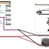
I know I post a lot on the forum regarding real trains, but today while working on the layout I came up with an issue I can't seem to resolve. Well here's the issue below.

Ok First before the issue. Recently I have 5 road crossings that I use Insulated Rail where I wire the Power to the Red on the Z-4000 and connect the common from my 2 Z-4000's both using 10 volts and 14 volts together on the common and connecting it to my ZW-L outside rail common. I have the MTH crossing flashers and connect the black wire on the Flashers to the outside Insulated Rail where I have the other Common wire on the track connected to the ZW-L. So when the outside wheel on the other outside rail makes contact with the Insulated Rail, the crossing lights and bell go on. So to help. I attached a diagram to the photo Stan gave to me and I'm sharing.

mth crossing stuff no relay method two handles

To Help, I Spaced The Words Apart to Read Easier:

Anyway, my MTH engines all work on the track including if I run my Lionel engines

convetional. But here's the strange part. I start up one of my Lionel engines and started

running it around our large layout and it runs fine until I come all the way back around and

come near and S curve where I have a bridge which is part of the inside track that is an incline

to our upper level which goes over the 2 lower mainlines I'm having issues with. Well my

Lionel diesel or steam starts to come under that bridge and the front engine lights flicker and

the engine stops and I lose total signal all the way under the bridge even until I pass under the

bridge to the other side and the signal comes back and it's the only spot on the layout I'm

having the issue with. Now it does happen to both sets of Mainlines on the lower level under

that bridge. So the question I have is, with insulating the rail in 5 different road crossing in

different corners of the Layout cause the signal loss not even near where it's at? I even tried to

use a feeder wire from the Base Ground and attach it to the outside rail of both sides of the

outside rail and it still does it even on a section of track that the rail isn't even cut and it's

maybe 10 feet away from the base. Now I know it's a signal loss problem, but my Legacy

Remote RED Light does not blink when I'm having a signal loss. (One thing though forgot to

mention when I started having this signal loss is when the track shorted when I was working

on the Crossing Flasher Insulated rail and by accidently touched the rail and the train stopped 

 and the red light came on and the train stopped in the spot I'm having signal loss. Now I 

assume a short on that track far away would have not caused me to have a signal loss. But I 

thought I would add that part). Anyway, sorry I made this so long, but I want to find out if 

anyone would know how to fix a signal loss on a bridge where a track goes over the 2 track 

mainline. 

Attachments

Images (1)
  • mth crossing stuff no relay method two handles
Last edited by Wrawroacx
Original Post

Replies sorted oldest to newest

The problem arises from signal towers or bridges that use the metal frame as the common ground to power it's lights.  The TMCC signal is also present on the common ground connected to the tracks.  Too much signal - particularly from above an engine - interferes with the engine's ability to receive the signal.  There are many threads on the forum addressing the "TMCC ground plane" and ways to correct poor signal.  In a nutshell, you need to a) use IR sensors, or relays, to ensure the power ground in your trackside accessories and signals is isolated from the track ground that carries the TMCC signal, or b) add a TMCC ground plane wire between the signal and adjacent tracks.  Option (a) always works for me, option (b) sometimes takes considerable experimentation to make it work.

So John, I should attach the crossing lights to a Relay as in diagram Stan gave me where there's a AZATRAX MRAPR-8? Would that fix the problem? Also can I have the Z-4000 commons on the back 10 Volts / 14 Volts be connected to the ZW-L or should I have a seperate Z-4000 just for crossing lights on 14 volts?

mth%20crossing%20stuff

Attachments

Images (1)
  • mth%20crossing%20stuff

Tom, a couple of changes to your relay connections:

1.  The Z4000 accessory voltage uses an internal common ground with track power.  You will have to use a discrete transformer for accessories to provide isolation.  A Z4000 is overkill, a small post-war transformer or wall wart will suffice.

2.  The connection between the accessory ground and the track ground cannot exist (see #1) or the TMCC signal will propagate to all ground circuits.

Tracker John posted:

Tom, a couple of changes to your relay connections:

1.  The Z4000 accessory voltage uses an internal common ground with track power.  You will have to use a discrete transformer for accessories to provide isolation.  A Z4000 is overkill, a small post-war transformer or wall wart will suffice.

2.  The connection between the accessory ground and the track ground cannot exist (see #1) or the TMCC signal will propagate to all ground circuits.

John, this does make sense. What I'll do is, I'll take the wire off for the crossing lights from all the Z-4000's and just apply the common line to one transformer that isn't beeing used much, probably to a separate Lionel Transformer. I'll see if that works.

Last edited by Wrawroacx

Actually I've been thinking. I kind of answered the question fast. What I'm meaning is, should I take all the common lines I have connected from the 2 Z-4000's 10 Volts & 14 Volts that go to my one ZW-L and put the crossing lights power onto a Lionel Postwar or other smaller transformer and put the common line from the ZW-L to the common on that smaller Lionel Postwar Transformer or other smaller that gets the power for the Crossing Lights? Would that bring back the signal?

Other thing is, I the bridge area where I'm having the issue, that bridge has a bliking red light and there's a board right underneath that area so that light blinks. I wonder that that would lose the signal also, because I'm not having any other signal loss anywhere else on the layout accept this 4 foot spot and I do have a large layout.

Hey, Tom Jr.,

While you may want to reconsider your power configuration wiring, the issue with the overpass bridge can resolved easily. This is a known and common issue.

For a test, tape a piece of small wire or any that you have under the bridge and run it to the nearest receptacle. Loosen the cover screw and wrap a bare piece around it and then snug it again. Now, run the tmcc/legacy engine under the bridge. it should be ok.

This earth ground  is not the same as the neutral AC, U or common power wire. Tracker John touched on it. That small wire should prevent the signal from the overpass interfering with the track signal below.

Then, find a nice path to route it.

Although electrically not a problem to have a "common" common or U, separate the accessory common from the track common to eliminate any issues with metal accessories causing any tmcc/legacy interference.

Watch this TMCC signal video starting at 15:22 for a few minutes to get the concept and the over/under track solution.

Let us know if that works.

Last edited by Moonman

Carl, I like to give thanks to my Dad. He helped on it. And yes the issue was me and him attached a Antenna Wire from the Legacy Antenna on the Base and ran it under the bridge and now the engine runs fine. So thanks to my Dad, it works now. So yes Carl, even though I had it done after you wrote this reply and didn't see it until now, your also right.

Add Reply

Post

OGR Publishing, Inc., 1310 Eastside Centre Ct, Suite 6, Mountain Home, AR 72653
800-980-OGRR (6477)
www.ogaugerr.com

×
×
×
×
Link copied to your clipboard.
×
×