


@stan2004, I have a question for you. I decided to put a few of these together, and a real oddity surfaced. I started out with the Toshiba TC74HC123APNEWF, and that worked as expected, I get about three feet of max sensing distance. I picked up some TI CD74HC123E parts that were claimed by TI to be compatible. They work, but... I only get a sensing distance of something over a foot at max settings! I chased my tail for a spell, then swapped one of the Toshiba parts in, and the operation resumed as expected. Would you expect this circuit to have that much variability just based on the different characteristics of the 'HC123? I actually expected very little difference, so I'm a bit surprised. I swapped several out and all changed the behavior, so I'm sure it's the 'HC123 that is the difference.

Toshiba datasheet suggests the pulse width is just less than 1.05 x R x C (R=205K max, C=-.022uF)
TI datasheet pulse width is 0.45 x R x C so just under 1/2 the pulse width for the same external R and C values.
So the Toshiba part would max out at 2-3 times the range of the TI part...which is apparently what you're seeing.
As I see it, this is flushing out the design issues exactly as intended. I'm not sure I'd need or want a 3 foot sensing range from detector to train...but again I'd like to hear ideas on where this would apply.
Attachments
Images (1)

@stan2004 posted:Toshiba datasheet suggests the pulse width is just less than 1.05 x R x C (R=205K max, C=-.022uF)
TI datasheet pulse width is 0.45 x R x C so just under 1/2 the pulse width for the same external R and C values.
So the Toshiba part would max out at 2-3 times the range of the TI part...which is apparently what you're seeing.
As I see it, this is flushing out the design issues exactly as intended. I'm not sure I'd need or want a 3 foot sensing range from detector to train...but again I'd like to hear ideas on where this would apply.
Stan, I confess I didn't even look at the datasheet, I just "assumed" that the two parts would be very similar in operation and timing. Lesson learned. ![]() I figure the longer distance operation can't hurt since you can also adjust it down to a couple inches. Since I only have a few of the TI parts, I'll just stick with the Toshiba parts.
I figure the longer distance operation can't hurt since you can also adjust it down to a couple inches. Since I only have a few of the TI parts, I'll just stick with the Toshiba parts.
John, any progress on receipt of your offshore parts yet? Just curious. ![]()
Rod
The off-shore parts were a bust! I ended up getting them from Digikey for a bit more money.
The NE555 parts from AliExpress were all defective, I put four of them in a board and none worked. So I fired up a simple test circuit on a project board and it turned out that only 9 or 10 of the 50 worked, obviously defective pulls. I decided to pitch them all, not taking a chance. I filed a dispute as well, I want my $3 back! ![]()
![]() The 'HC123 parts worked, but as illustrated in previous posts, I failed to consider how much different they would be than the others I was using. I decided to get get more of the Toshiba parts to keep the parts kit consistent. The caps from off-shore worked fine, I got the extra resistors locally as they're cheap anywhere. I also rounded up enough regulators to equip them all, turns out I have a hundred from another build that were left over.
The 'HC123 parts worked, but as illustrated in previous posts, I failed to consider how much different they would be than the others I was using. I decided to get get more of the Toshiba parts to keep the parts kit consistent. The caps from off-shore worked fine, I got the extra resistors locally as they're cheap anywhere. I also rounded up enough regulators to equip them all, turns out I have a hundred from another build that were left over.
I also found some terminal strips that work in the board, so I'll have screw-terminals for the connections. It ends up costing a bit more, but it's a much neater installation.
I think the final parts are in my mailbox, I'm going to go up and fetch them today. I'll just have to kit up the parts and I'll be set...
OK, the parts are in. I have a few of these built, I was tinkering with a couple of them. I built a couple with the 10A relays, and the rest with the 3A relays. A kit will consist of everything you see here, enough to build a complete working board as shown. Kits will be $15 for the 3A relay version and $17 for the 10A relay version. Note that there is no adjustment or calibration necessary, other than setting the detection range and relay trip duration pots, it's all fixed components. All connections are side entry screw terminal blocks.
If anyone wants one of these assembled versions, add $15 for the labor for assembly/testing.

Attachments
Images (1)

@sjbuff posted:HC-SR04 Ultrasonic Sensor
Train Detection Block Signals
I thought I share the use of this ultrasonic sensor, I was able to utilize the sensor in my outdoor dead rail layout as a train/block detection on my layout.
Since converting the Baldy & Palms Railroad to “dead rail” in early 2021, the track detection circuit on the upper loop has been functioning correctly about 80% of the time. The reed switch circuit would get triggered by the magnets at one end of the block and not at the other end. This made the circuit go out of sync. I decided to try several other sensors with the Arduino to find a suitable solution. I tried the current sensor, voltage sensor, relay circuit, and the IR sensor, none of these performed reliably.
I discovered the HC-SR04 ultrasonic sensor and decided to experiment with this sensor. I also created a better Arduino code with the HC-SR04 sensor. I adapted the HC-SR04 sensor to fit in a small signal shed to match and blend with the block signal. The Arduino code is written so the HC-SR04 monitors motion from about 4 to 8 CM across the track. When a train is detected on one end of the block, the signal will turn red, and remain red until the train exits the other end of the block, at which the signal will reset to a clear green signal. This can be used with two or three aspect signals. The code just needs a few lines of code activated. The circuit has performed very well, so I plan to incorporate this circuit in other trains detection blocks on the layout. Check out the YT video for the Arduino code sketch and circuit design. YT Video - HC-SR04 Block Signal
Hope this post helps other outdoor layouts having the same problem and eliminate the need to put magnets on locomotives and rolling stock.


To me this is the hard way to do this, in g scale we use a magnet and reed switch to a relay it can be self latching with a second reed switch as the kick out. All off the shelf and very cheap as well as trouble free.
@ThatGuy posted:To me this is the hard way to do this, in g scale we use a magnet and reed switch to a relay it can be self latching with a second reed switch as the kick out. All off the shelf and very cheap as well as trouble free.
He pretty clearly stated that the magnets were not working reliably enough, so maybe this is the "reliable" way. ![]()
@stan2004 posted:
Toshiba datasheet suggests the pulse width is just less than 1.05 x R x C (R=205K max, C=-.022uF)
TI datasheet pulse width is 0.45 x R x C so just under 1/2 the pulse width for the same external R and C values.
So the Toshiba part would max out at 2-3 times the range of the TI part...which is apparently what you're seeing.
As I see it, this is flushing out the design issues exactly as intended. I'm not sure I'd need or want a 3 foot sensing range from detector to train...but again I'd like to hear ideas on where this would apply.
As described above, I was using the equation: pulse width = K * R * C. In this case K=0.45 for T.I. and about 1.0 for the Toshiba per the datasheet I pulled off the web.
There is something squirrely going on though. I dug thru my parts stash of 74HC123 chips and estimated the "K" constant in the Range adjustment circuit.
0.38 Texas Inst. just received from LCSC - presumably a fresh date code though not clear what year
0.44 ST Micro date code 1998
0.49 TOSHIBA #1 date code 1989
0.51 TOSHIBA #2 date code 1989
1.0 National Semi date code 1990
So in this sample of 5, most were around K=0.45 and the odd-ball was K=1.0. So it was the National chip from 30 years ago that has the longer pulse time like your current Toshiba part. My older Toshiba parts from 30 years ago behave like the modern T.I. part. The 74HC logic chips are fairly long in the tooth and there have been comings-and-goings in the chip business. But it's known that for legacy chip families like this that as manufacturers upgrade there chip fab equipment certain characteristics can change - in this case apparently the K parameter.
All this is a moot point since you're "shipping" fresh Toshiba parts which provide the extended Range adjustability.
@gunrunnerjohn posted:He pretty clearly stated that the magnets were not working reliably enough, so maybe this is the "reliable" way.
Then he is doing something wrong, in G Scale we have used magnets for years with 100 percent reliability
@stan2004 posted:All this is a moot point since you're "shipping" fresh Toshiba parts which provide the extended Range adjustability.
Yep, I decided that all of the stuff I had here should have the same characteristics, makes it easier to explain what's happening. ![]()
@ThatGuy posted:Then he is doing something wrong, in G Scale we have used magnets for years with 100 percent reliability
Maybe so, I can only go on what was written, I wasn't there. However, for the magnets, you have to add them to every train.
@gunrunnerjohn posted:Maybe so, I can only go on what was written, I wasn't there. However, for the magnets, you have to add them to every train.
Very true, the magnets are sold by the dozen and are attached easily. I have a very large stable of LGB/Arista-Craft/USA trains and it went 1-2-3
Ok John I am in for two of the 10A version. I would also be in for 6 boards if you have extra. Zip is 86351 for figuring shipping.
Rod
@Rod Stewart posted:Ok John I am in for two of the 10A version. I would also be in for 6 boards if you have extra. Zip is 86351 for figuring shipping.
Please send me an email and we'll get you fixed up.
I'd like a couple of kits too, I sent you an email to your profile address. Thanks for putting all this together too.
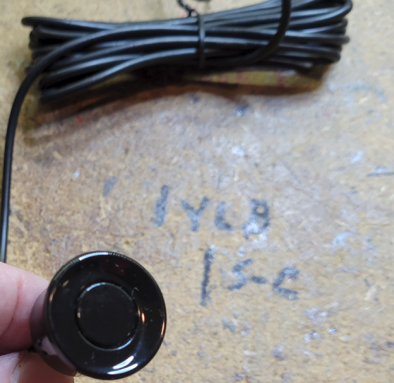
Here's something that we discussed, a remote cable to connect the sensor to the board. It looks like it doesn't change anything except the mounting of the sensor. The cable is build using Dupont Connectors. I didn't see any adverse effects, but the cable is only a foot long. However, I suspect any reasonable length cable would work here.
An important note: Since the cable has no keying, I labeled each end and the board with the signals, if you reverse it, I'm pretty sure the sensor will die a horrible death!


Attachments
Images (2)

I like that idea of the 4 pin cable all in one for the remote sensor mounting.
I set up one of these on the bench, and I was quite impressed with how precise the triggering range can be. It works within about an inch in distance. It would trigger every time at, say 10 inches, but never at around 11.5". I have to think this resolution might work for some applications better than an IR sensor that reflects off the target. The IR boards just reduce the sensitivity of the receiver to change the range, that's a very inexact method of adjusting range. I fooled around with a variety of different materials in front of the ultrasonic sensor, and it was amazingly consistent with any of them.
BTW, still have a few sets of parts all kitted up if someone want's to build one or more of these. ![]()
This is just a 'FYI' for anyone that might be interested and may not know of other sensors similar to the HC-SR04.
Finally got around to looking at the video link posted by Consolidated Leo on the first page of this thread. (I'm a little behind as usual) While the video was Arduino related, there was another sensor mentioned that can be set to emulate the HC-SR04 sensor. The Sensor itself is supposed to be waterproof, but obviously the driver board is not waterproof.

Since it can be set to emulate the HC-SR04 I was thinking it just might work with Stan's circuit that GRJ has made the PCBs and kits for. I have not tried this and I know it adds an extra board. Just thought it might be an option for consideration if anyone was interested and unaware of other sensors like the HC-SR04? I was thinking it might be smaller and easier to disguise along the tracks with the driver board being remotely connected to the sensor, using a fairly long cord (which is included). These are a bit more costly than the HC-SR04s, about $3.60 from AliExpress at the time of this post. You can see it here - Waterproof Ultrasonic Module JSN-SR04T / AJ-SR04M.
There are better instructions available at the DroneBot Workshop website (from Consolidated Leo's link above). The AliExpress instructions were somewhat lacking, like some of the instructions provided with other off shore devices. They also talked about one more waterproof sensor there, but it was described as more of a switch and I didn't think it would work with Stan's circuit without modifications (probably major), which I thought would be above my abilities? It's also quite a bit more expensive.
Also as Consolidated Leo described above, complete details are provided (including code) to make either of these sensors (including the HC-SR04) work with an Arduino if anyone is interested. It's a good learning video if you are new to Arduinos and the DroneBot website is also a good learning site. The website not all Arduino only, it also includes electronics tutorials, helpful if you are trying to learn more.
Attachments
Images (1)
OK, I'm curious, I bought a couple of these. I got them on Amazon as I can get them tomorrow, and I'm not a patient man. ![]() It looks to be jumper configurable to emulate the HC-SR04. The little sensor head would be easier to hide on a layout, a plus.
It looks to be jumper configurable to emulate the HC-SR04. The little sensor head would be easier to hide on a layout, a plus.
Hopefully that's exact HC-SR04 emulation or really close anyway so it works with the already designed circuit and PCB. I've forgotten the other 4 modes already, but didn't look that closely at those. I was thinking the same thing about hiding them on a layout and they have a fairly long cord, or at least looks to be fairly long. I'll be interested in your opinion of them and getting them the next day is definitely very nice, no waiting required!
Amazon seems to think I'll get them today. ![]()

Attachments
Images (1)

Well, I can report that the JSN-SR04T works just like the HC-SR04 in the board. The only difference I see is a slight variance in the distance setting, the closest setting doesn't work, other than that, it seems pretty much like the HC-SR04 in operation. Obviously, I didn't test all the other modes that require a different hardware platform.
That's good to hear, I'm glad it worked. How was the remote sensor part? Hopefully it was a bit smaller and would easier to conceal on one's layout somewhere than the HC-SR04. They are a little more expensive, but might be worth it for some applications. And that was a mighty quick delivery too! I wouldn't have time to forget why I ordered it with that fast of a delivery.
@gunrunnerjohn posted:Well, I can report that the JSN-SR04T works just like the HC-SR04 in the board. The only difference I see is a slight variance in the distance setting, the closest setting doesn't work, other than that, it seems pretty much like the HC-SR04 in operation. Obviously, I didn't test all the other modes that require a different hardware platform.
Good news John. That should mean that other than any cost considerations, the JSN-SR04T should work every bit as well. Were you able to determine what the minimum useable setting distance is?
Rod
@Rod Stewart posted:Good news John. That should mean that other than any cost considerations, the JSN-SR04T should work every bit as well. Were you able to determine what the minimum useable setting distance is?
Rod
Rod, the minimum distance seems about the same, 3-4 inches.
@rtr12 posted:That's good to hear, I'm glad it worked. How was the remote sensor part? Hopefully it was a bit smaller and would easier to conceal on one's layout somewhere than the HC-SR04. They are a little more expensive, but might be worth it for some applications. And that was a mighty quick delivery too! I wouldn't have time to forget why I ordered it with that fast of a delivery.
The remote sensor is certainly much smaller than the whole HC-SR04 board, about 1.25" in diameter and an inch or a bit more in depth. You pay a little more at Amazon, but next day delivery makes up for some of that. ![]()
@gunrunnerjohn posted:Rod, the minimum distance seems about the same, 3-4 inches.
...
Is there any marking as to which version of the JSN-SR04T you got?

In reading some reviews, it appears the original version was 5V only, but there is a more recent version that additionally operates at 3V (not that 3V operation is needed in this case). Additionally, as per above, the minimum distance for whichever version this is, is 25cm or ~10 inches which I'd think is too far for most O-gauge trackside occupancy detection?
Also, in at least one review, it was claimed that the 4-pins changed definition between versions. Hard to know what to believe. ![]()
Attachments
Images (1)
I got the AJ-SR04M, and indeed the detection distance is 8" on the two I got. Mine appears to be the 5V only version, but it does plug right into my tether equipped board.


Attachments
Images (4)


Well I received 2 kits from grj and got one built today. Hooray; it works just as advertised! ![]() All needed parts are included in the kit, including an HC-SR04 sensor and your choice of 3 amp or 10 amp relay. And they all fit quite well. The parts packaging is excellent; well done John.
All needed parts are included in the kit, including an HC-SR04 sensor and your choice of 3 amp or 10 amp relay. And they all fit quite well. The parts packaging is excellent; well done John.
I did a little testing of the range and reset delay, with the following results:
Range: Min= 3/4", 1/4 turn = 3", 3/8 turn = 7.5", 1/2 turn = 14", 3/4 turn = 27"
Delay: Min = 1 sec, 1/4 turn = 5 sec, 1/2 turn = 20 sec, 3/4 turn = 40 sec, full CW = 45 sec
These are all with the particular set of components in the kit, YMMV. But adjustability is good and will cover most of our model RR needs I figure.
The only things I would suggest are: 1. Take care with the LM7805 TO-220 Vreg mounting. It's #1 pin is the far left one when viewed from the inscription side, so the chip mounts with the inscription facing outwards and the tab towards the center of the board.
The pads for Q1 and Q2 are tiny and close spaced. It's fiddly and very easy to solder bridge them. Take care and examine afterwards with a magnifying glass. I would have preferred the TO-92-100 pattern, but that's just me.
Kudos to the OP for the idea, Stan2004 for the circuit design, and grj for the board design and putting the kits together!! ![]()
I plan to install a couple of these once we are back home and see how they work in the real layout world.
Rod
If it had it to do over again, I'd actually use the footprint for the LM7085T, I used my footprint for the RECOM switching module. I didn't think the LM7805 would handle the larger relay, but with a heatsink it works fine. I normally mount the regulators the other way, so that one was just the lack of a second spin of the boards. I think I'll start using the TO-92-100 pattern in the future as I hear you about the transistor pattern, it is tricky.
Just in case I do more boards, here's what the mods would look like.

Attachments
Images (1)

Now you're talking John; that revision looks great! But this thing all in all looks like a home run to me as is. Can't wait to try them on the layout. And the isolated relay common covers all the bases! I especially like the idea that a range of 4" to 8" should be easily doable, and hopefully will mitigate unwanted reflections. We shall see!
The little transducer cones on the HC-SR04 board are only 5/8" diam and project a little less than 1/2" from the face of the board. Plus they are an inobtrusive aluminum color. So I think it will be easy enough to disguise them in some sort of small trackside cabinet structure, especially if tethering them to the main board located below the layout. All good.
Rod
When the changes are small, I like to keep them current in case I run another set of boards. I still have boards and parts, so it ain't happening yet. I was kinda' hoping a few more people would jump in and do some testing to see what if we turned up any more interesting usage notes. ![]()
That all sounds very good with the kits and their operation! My kits seem to be stuck in downtown KC (since Thursday). Fortunately, they now say Monday delivery! I hope to have one built up next week sometime.
And as Rod said above, thanks to sjbuff for the original idea and sharing it here, thanks to Stan for the circuit design and thanks to GRJ for the PCB design and getting the kits together!
'Informed Delivery' emailed me that they would arrive on Friday! Missed that one, then missed Saturday. Hopefully they will get it right on Monday, we will see! At least they claim to know where it is anyway, so that's good!
I guess Informed Delivery isn't that informed. ![]()
![]()
I've had a package rotate around the Phila main post office for almost two weeks before it finally left and got delivered. I have no idea what they were doing with it all that time!
I have been doing a little more playing with my first kit build, and have some observations.
At idle (with 14VAC board supply) with no relay triggered the LM7805 Vreg is barely warm to the touch. After the 10 amp relay has been triggered a few minutes it gets quite warm though, over 40C, perhaps 50C or so. Don't have my temp gun here so can't be sure, but definitely a small heat sink would be a good idea. I think it is running a fair bit shy of shutdown high though. The 10 amp relay draws about 90 ma of coil power, but the 3 amp version draws way less. So it would likely be just fine without a heatsink. The tiny Q1/Q2 transistors get only slightly warm to touch.
The transducers have a cone of dispersion that is about 15º each side of centerline at 3" away; and about 8º each side at 7.5" away. So it is more of a "parabola of dispersion" I guess, that is about 1.6" diameter at 3" distance, and about 2.1" diameter at 7.5" away. Flat surfaces parallel to the axis of the parabola (such as a tabletop) don't reflect the signal. But any structure or something like track or roadbed that is within this parabola will likely cause unwanted reflections. This means that at a distance of 8" away the transducers will have to be mounted AT LEAST 1-1/4" above top of rail to be safe. This would be an issue if aiming the transducers at say truck height, but aiming at any part of a car body should work fine. Even an unloaded flat car should trigger the relay, as long as the side of the deck is within the dispersion parabola. For O gauge tubular or Fastrack for instance, a height above grade of about 2" for the transducer centerline looks like it should work. This needs to be confirmed in the real world though! ![]()
For distances over 8" the cone will be somewhat bigger; which might require the transducers to be mounted a touch higher, but I did not check this out yet.
Some may recall the first versions of the 153IR had the annoying habit of untriggering after the delay timed out, even if the train was still stopped in front of it. This was fixed in later versions thankfully. But this new device stays triggered as long as something reflects the signal, so all is good.
Rod
Did you ever consider using the Sharp distance measuring sensor? I have used it with good results in several projects.
Add Reply
Sign In To Reply
