In an earlier post I explained each of the elements in the circuit, but I will repeat most of the explanations here. The direct answers to your questions are in bold. I used the circuit boards provided by American Models because they did contain usable parts and spanned the two trucks from which to draw current. I started by disassembling the car, removing the circuit board, and de-soldering and removing the incandescent light bulbs.
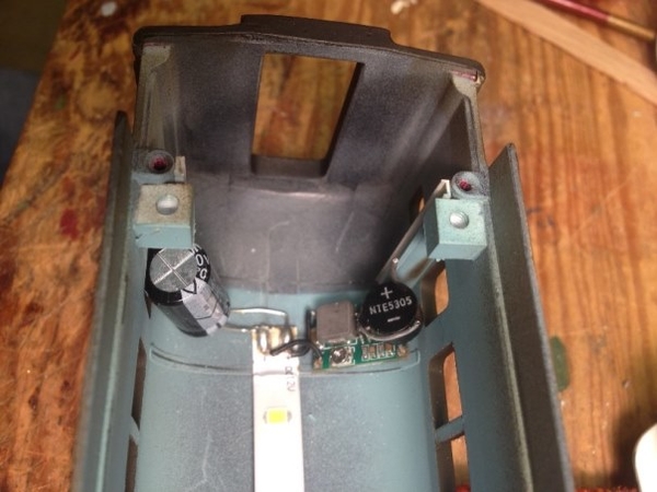
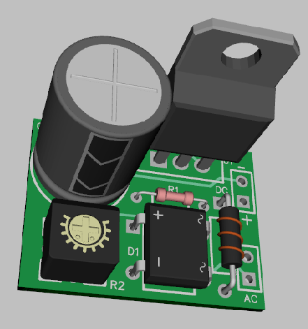
I drilled a small hole through the printed circuit line to break the connection as described on the left of the picture below. I did this so that I could insert a 22mH choke to bridge the connection. The choke was a recommendation for anyone who wanted to use the MTH DCS system and prevent interference with its signal to DCS-controlled locomotives. The choke is the black rectangle with the red outline. The break is represented by the disconnected yellow line below the choke image. If the car will never be used on a DCS system, the choke is not necessary.
The next element is the bridge rectifier, the gray circle in the diagram. The rectifier's job is to take in either DC current or alternating current and send out only the DC current required by the LEDs and the buck-boost module. The two yellow lines represent the current from the two trucks and connect to the proper legs of the rectifier. The rectifier cannot span the PCB board lines that are parallel on the board because those two lines are to be reserved for the "rectified" or "corrected" DC current out from the rectifier.
The rectified current out from the rectifier is represented by the black ( -) and the red ( + ) lines that can connect to the parallel printed circuit board lines on the PCB board. Be sure to note which line is going to be positive and which is negative because the buck boost converter has to connect to the right one. The capacitor, the blue cylinder in the diagram, also has to connect to the correct lines because it has a positive leg and a negative leg (represented by the white marking down the side of the capacitor. Capacitors have markings on them to show which leg is negative.) The idea behind the capacitor is that it acts as a "battery" to temporarily store a charge on it so that lights don't flicker when current from the wheels on the trucks sees slight interruptions due to dirty track or crossing switches. Capacitors DO reduce flicker; but unless track and wheels are clean in the first place, I found that they don't eliminate it.
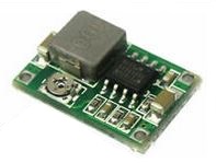
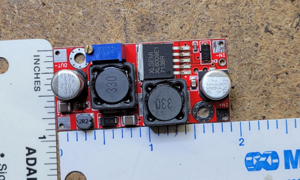
The buck-boost converter has pads on each of the four corners for connections. Each is marked--two on one end for input and two on the other end for output. The red and black lines on the diagram represent the positive and negative current from the capacitor or, more easily, the correct parallel printed line on the PCB board. I just used the holes from a removed incandescent light bulb to solder a connection from the positive or negative line to the correct positive or negative input pad on the buck-boost module.
The buck-boost converters I used had voltage output settings too high for the LEDs when I removed them from their packages. To make initial adjustments, I hooked each one up to wires with alligator clips on both ends of the wire. I attached one end of each wire to the input ends of the modules and the other ends to the track. I applied 10 volts from the track and tested the voltage at the output pads of each converter module. The initial voltage was between 25 and 30 volts, so I turned the brass rheostat screw on each module counterclockwise so that the measured output was about 7-8 volts. If the track voltage was 5 volts, the module put out 7-8 volts. If the track voltage were 12 volts, the output would still be 7-8 volts; and that is how the lights stay "constant" even when the passenger train is moving fast or slowly. (It's easiest to adjust all the buck-boost converter modules in a batch rather than adjust each one to complete one car, then go to complete another car, and so forth.) I set all the readjusted modules aside. When I need one for the PCB board, I glued it to the underside of the PCB board, away from any windows so that it would not be visible. Then it was easy to solder connections to the module's pads to the old holes in the PCB board using small wires.
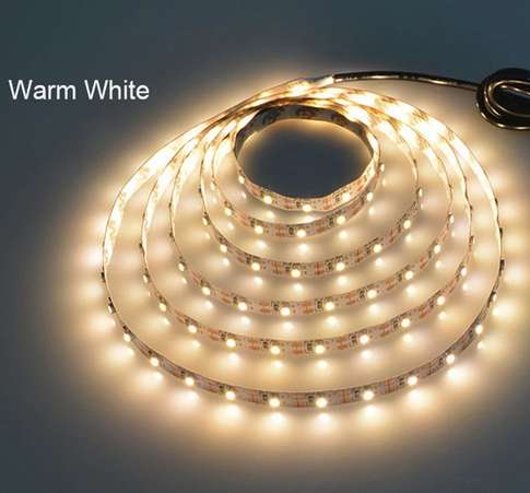
The LED light strips have adhesive on the the reverse side. Before I attached them to the PCB board, though, I soldered wires from the converter's output pads to the correct positive (red) and negative (black) inputs on the LED strips. The strips are marked as to + or - connections, and they have small solder spots on them to make the connection easier. (Getting a good connection at this point , however, was the most difficult part of the assembly and required testing multiple times to make sure the LEDs lit up.) Once I was convinced the connections were good and the LEDs lit up, I stripped off the waxy paper over the adhesive and glued the strips to the bottom of the PCB boards. Most, if not all, LED strips already have resistors attached to them to control current. The buck-boost converter alters the voltage to alter the light output from the LED strips. I used 12-volt strips because I already had some, and this type was the easiest to find.
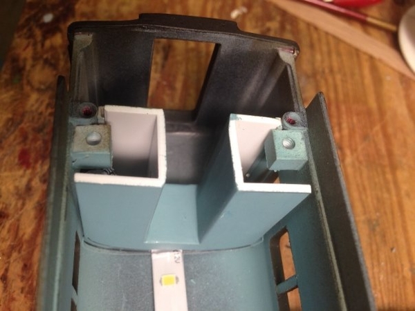
I reattached the PCB boards to the under frames of each car but left the upper body off for further testing. Once I had finished all the cars--a long process because I included heavyweights, streamliners, Amtrak cars, and cabooses--I lined up all the cars of the same type on the same stretch of track and applied current to the track. The lighting varied a bit from car to car, but adjusting the brass rheostat on each converter allowed me to make the lighting entirely uniform for each car. As gunrunnerjohn points out, adjusting current is more controllable than adjusting voltage; but if the voltage from the buck-boost converter stays well below 12 volts for 12-volt LED strips, there is little danger from burning them out. Each car now had the same amount of illumination no matter if the track voltage was varied from 4.5 volts (for American Models DC locomotives pulling cars) up to 15 volts (for American Flyer Legacy AC locomotives). I moved each car along the track to check whether the connections were sound. After each car passed, I reattached the bodies to the frames.
The benefits outweigh the work involved: uniform lighting from car to car, uniform lighting at any speed above that requiring more than about 4 volts, low current draw, and minimum heat generated in each car. There are other ways to illuminate cars, but this worked for me.
Terry