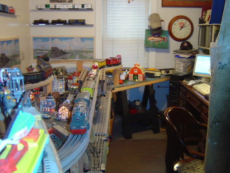
Trying to learn all I can about electricity to hook up DCS, (soon Legacy), turnouts, accessories, toggle switches, etc.  But still have some noob questions (will probably have a few more as I go along) - would appreciate any help:


  • Is 3-rail DC or AC?  I'm under the impression that it's DC but can't seem to confirm.


  • For purposes of DCS, I'm star pattern wiring track.  I hooked up my first turnout (Atlas O No. 5).  It will be wired to a separate power source and not thru TIU.  I did power drops at all 3 legs and screwed wires into a Home Depot terminal block, but didn't connect the terminal block to the buss yet - so it is not connected to electricity yet.  When I flipped on my Z4K (testing my trackwork on both sides of turnout), it tripped.  Determined that having the power drops screwed to the unpowered HD block was the cause.  I disconnected the power drops from the HD block and everything was fine.  Why?  Now concerned that if I add re-connect those power drops to the block and power it, I might go up in flames.


  • For turnouts and accessories, I will be using a 16 gauge (or should I use 14 AWG?) buss wire.  I have the OGR stranded that comes with an outer gray sheath.  Do others keep the hot/common in the outer sheathing and just make openings where they need to connect things (for neatness)?  Or completely take off outer sheathing?


  • Should I connect the buss wire to the accessory port, or to a port with more power?  I will have approx 3 - 5 turnouts on each loop and a normal amount of accessories (for a 14 x 33 foot layout).


  • Should the hot and common buss wires each make a complete loop?  Meaning, should the wires make a big circle - both ends of each wire terminating at the same spot they originated - the same hot or common port?  Or should only one end be connected  to the respective port?  


Thanks very much - really appreciate it.  Don't know anyone in my area that is in our hobby, so you guys are invaluable.


Peter

Original Post

Replies sorted oldest to newest

DCS puts AC on the track.  Inside the locos, it is rectified to DC.  16 gauge is fine for turnouts and most accessories.  I recommend 14 for track power.


I use a 12-gauge common buss for my DCS layout, connected to the transformers' U posts at each end for optimum electrical distribution.  There was recently a lengthy thread on this subject.  I feed each block hot directly from the control panel, by a single feed per block.


If you're asking about wiring for DCS, you ought to post this on the DCS forum, where it will bring a host of different approaches.  My (and many others') use of common buss is anathema to many, so while they say you can't use it for DCS, I blissfully (blithefully?) run my DCS layout.


I don't know what you mean by connecting a buss to an accessory port.  Depends on what it feeds.


What geographic area?


PJB,

  I always recommend to people setting up a DCS/TMCC-Legacy layout that they start with the OGR DCS Video Guide and Barry's  DCS O Gauge Companion 2nd addition book, watch the OGR DCS Video several times, Rich Melvin does a great job with the visual education, especially for beginners.  Read and follow Barry's incredible education on building a DCS layout that incorperates TMCC & Legacy.

Wiring a DCS/TMCC-Legacy layout is explained fully in Barry's book, use it track side as you build and end up with all 10's thru out your DCS layout.


One other note when Purchasing the DCS equipment, you want to purchase the most recent version of DCS, Rev L  4.20.  Don't bother purchasing an older model.


When you are done watching the video and reading the DCS O Gauge Companion

return to the forum and the men will help you with anything you have questions on.

There are men here who run with all different kinds of track and switches and combinations of them also. 


One other thing you should decide is whether you are going to build a reality

type layout or a toy train type layout, it will help you on deciding which track you want to build your DCS layout with.


Good luck and welcome, you might want to post this thread in the DCS section also.


PCRR/Dave

 Tin Plate DCS layout using FasTrack, a little boys dream world come true.


Last edited by Pine Creek Railroad
Guys, I appreciate the posts but my questions have nothing to do with DCS. Please take another look. I own Barry's book, the DVD and countless other sources. They discuss wiring needs for DCS. They don't discuss Home Depot terminal blocks or why the setup I described would trip my Z4K, whether the turnout/accessory buss should be a loop and have both ends connect to the same post, sheathing, etc. Would really appreciate help related to the specific questions posed. Thanks again.
Originally Posted by PJB:

Trying to learn all I can about electricity to hook up DCS, (soon Legacy), turnouts, accessories, toggle switches, etc.  But still have some noob questions (will probably have a few more as I go along) - would appreciate any help:


  • Is 3-rail DC or AC?  I'm under the impression that it's DC but can't seem to confirm.


  • For purposes of DCS, I'm star pattern wiring track.  I hooked up my first turnout (Atlas O No. 5).  It will be wired to a separate power source and not thru TIU.  I did power drops at all 3 legs and screwed wires into a Home Depot terminal block, but didn't connect the terminal block to the buss yet - so it is not connected to electricity yet.  When I flipped on my Z4K (testing my trackwork on both sides of turnout), it tripped.  Determined that having the power drops screwed to the unpowered HD block was the cause.  I disconnected the power drops from the HD block and everything was fine.  Why?  Now concerned that if I add re-connect those power drops to the block and power it, I might go up in flames.


  • For turnouts and accessories, I will be using a 16 gauge (or should I use 14 AWG?) buss wire.  I have the OGR stranded that comes with an outer gray sheath.  Do others keep the hot/common in the outer sheathing and just make openings where they need to connect things (for neatness)?  Or completely take off outer sheathing?


  • Should I connect the buss wire to the accessory port, or to a port with more power?  I will have approx 3 - 5 turnouts on each loop and a normal amount of accessories (for a 14 x 33 foot layout).


  • Should the hot and common buss wires each make a complete loop?  Meaning, should the wires make a big circle - both ends of each wire terminating at the same spot they originated - the same hot or common port?  Or should only one end be connected  to the respective port?  


Thanks very much - really appreciate it.  Don't know anyone in my area that is in our hobby, so you guys are invaluable.


Peter

3 rail is usually AC put out by the transformer. There is a bridge rectifier in the engine that converts it to AC for the motors.


Cant figure out your wiring ,it is not specific but if the breaker trips you have a short somehow.


Unless you have a lot of accessories or very long runs of wire #16 should be fine.


turnouts really do not use a lot of current and then only briefly. Accessory port should be OK unless other accessories pull a lot of current.


If you make a big loop voltage drop will be decreased. However a common bus is not recommended for DCS as far as signal quality goes but some people do it. Star wiring is recommended.


Dale H

Dale H - thanks. Regarding the wiring, I'll try to describe better: the turnout is connected to surrounding track on all three legs. That track is all wired thru my TIU to my Z4K The turnout has power drops at each leg that go through the table in order to electrify it through a separate power source (and not going through TIU) - in addition to whatever power it might be getting from the surrounding tracks connected to it. All 6 power drop wires from the turnout are screwed into the Home Depot terminal block. The terminal block has 8 posts. 6 of the posts are taken by the power drops and the other two don't have anything attached to them yet - But they would be where I would connect power to the terminal block. When I turn on the Z4K it trips. If I disconnect the 6 wires from the currently non-powered Home Depot terminal block, everything is fine. Thanks! Peter

The Atlas turnouts have switch machines with 3 terminals. They should have nothing to do with track power center rail feeds. They can share a common with the track but do not have to.  I do not run DCS so I can not help you much with TIU as I am not familiar with it.


I throw my Atlas machines with a toggle switch and capacitor discharge,shown here


www.jcstudiosinc.com/BlogShowT...=411&categoryId=


Maybe someone with the TIU can chime in here because I am not sure if the power feeds you describe are track power or machine power. Somehow you are shorting the Z4000.  The stock Atlas machines can only handle intermittent power so be careful not to burn them out.


Dale H


"Guys, I appreciate the posts but my questions have nothing to do with DCS."


In case you didn't notice, you started this thread by saying:


"Trying to learn all I can about electricity to hook up DCS..."


The answers I gave related to and responded to your specific question about AC vs DC and electric distribution.

PJB,

   My response was based on the " Trying to learn all I a can about electricity to hook up DCS." and you go on from there.  Maybe you need to restate your exact question, so we can answer you in a different way.  The answers I gave, are what you need to learn, as to how to set up, a complete DCS layout, wiring and all. 

It sounds like you are wired incorrectly and have a short some place at the very least.

PCRR/Dave


Last edited by Pine Creek Railroad

PJB,


You say that you have a total six power drops from three legs. Am I correct in assuming that you have a center rail drop and an outside rail drop from each leg?


Please describe the Home Depot terminal block. Are you talking about a barrier strip as I describe in my book? If that's what it is, then each row of screws on the strip should be electrically isolated from each other.


However, since your breaker is tripping, you obviously have a short. In other words, at least one or more center rail drops are connected to one or more of your outside rail drops. This will cause a direct short.


We need more information to properly diagnose your problem.


Originally Posted by DennisB:

PJB,


You say that you have a total six power drops from three legs. Am I correct in assuming that you have a center rail drop and an outside rail drop from each leg?


Please describe the Home Depot terminal block. Are you talking about a barrier strip as I describe in my book? If that's what it is, then each of the screws on the strip should be electrically isolated from each other.


However, since your breaker is tripping, you obviously have a short. In other words, at least one or more center rail drops are connected to one or more of your outside rail drops. This will cause a direct short.


We need more information to properly diagnose your problem.


I’ve posted some photos, as they might better explain.  But basically, I have my Atlas O No.5 turnout with a power drop (Atlas O track joiners with connected power feeds) connected to the center and outer rail on all three turnout legs.  And the other ends of those power drop feeder wires are connected to a (currently) non-powered Home Depot “Dual Row Terminal Strip.” When I turned on my Z4K, this arrangement tripped it.  When I disconnected the power feeds from the non-powered strip, I was fine.  


Specifics –


  • I powered the turnout this way because everything I’ve read says putting power drops on all three legs is highly recommended. 


  • I noticed this morning that two of the three legs have a feeder wire to the Right-hand outer rail while the other leg (the straight leg exiting the turnout) has the feeder connected to the Left-hand outer rail - you can see this in the close-up of the turnout pic below.  


  • The turnout is not electrically isolated from the tracks that connect to its three legs.  


  • In the pic, you can see where the feeders were screwed in: the 6 posts that don’t have a screw in them right now.  The remaining posts (ones with screws) are where I intend to connect power to the strip – but haven’t yet.  When I flipped on the Z4K with power feeds connected to the non-powered strip, the Z4K tripped.  When I disconnected the power feeds from the strip (as it currently appears in the pic), all was fine again. 


  • I've posted a pic of the overall track I've laid so far so you can see where the turnout is in relation to everything else.


Dennis – I think I have this turnout wired the same way as the one shown in pics 2-6 and 2-7 in your incredibly helpful book.  Based on 2-9 pic, I would say that the strip I used is very similar/the same to the one you used, except that it has 2 more posts.  If my chosen strip is not recommended, I have the receipt. 


RJR / PCRR Dave - Apologies if my first post was unclear.  Basically, the lead-in paragraph was meant to say the following: “I am trying to get familiar with all aspects of electrifying the layout.  And, that I am asking a bunch of (probably silly) questions because I have no real life experience.”


If you need any more information to help provide your thoughts, please let me know.  


Thanks!


Peter   

IMG_1120[1]

IMG_1126[1]

IMG_1123[1]

IMG_1122[1]

IMG_1124[1]

IMG_1125[1]

Attachments

Images (5)
  • IMG_1126[1]
  • IMG_1123[1]
  • IMG_1122[1]
  • IMG_1124[1]
  • IMG_1125[1]

Whether or not you will be running DCS is important, because there is one major difference.  With conventional only, multiple feeds to the center rail of a block are fine.  With DCS, the word is that there should only be one, as more MAY cause signal problems.


I do not agree with the premise many DCSers follow, that you can't have a ground bus and must have all wiring emanate from a single terminal block.  I, as well as many other forumites, use ground bus (which I have connecting to U at each end, plus a jumper from U to middle of loop).


I am not kindly disposed towards those rail joiners.  I feel that they may not always make the best, soundest, least resistive contact.


I didn't see any "silly questions."

PJB,

  The decision you need to make is whether you are wiring for a DCS/TMCC-Legacy layout or not, building a DCS layout wiring and all from scratch is different than just conventional wiring.  As RJR points out many of us vary this in our own way to end up with the best results.  I see no "silly" questions, however you need to decide what kind of a layout you are constructing and stay with those disciplines needed to achieve the total engineering package.

If you are going to run DCS use the wiring Barry outlines in his book, with maybe some slight modification for your specific needs.

PCRR/Dave

RJR / PCRR Dave - thought I covered this in my first post?  No matter, probably not enough detail.  Chalk it up to my inexperience. 


I am star pattern wiring the TRACKS for DCS.  Track blocks with one power feed (14 AWG) to the middle of each block, exactly as specified in Barry's book.  Again, per Barry's book, if you plan to have the turnouts or accessories command controlled, you install an AIU to the AIU port and connect things that way.  I plan to operate turnouts and accessories conventionally.  To power all these conventional items, I (maybe erroneously) decided to power them via a buss wire (16 AWG) that is completely separate and apart from the star pattern wiring to the track blocks.  And, this separate buss would run to a completely separate power source.  Granted, the turnouts are connected to the rest of the track that is getting power from the Z4K that runs through the TIU, so the signal will be going through the turnouts too.   


For illustration purposes:


Track power:  imagine I have a control panel.  On it is a Z4K that is connected to a TIU (Fixed In #1 and #2) for my double mains.  The wires coming from Fixed Out #1 and 2 connect to MTH terminal blocks set on the panel (one for each main).  From the terminal blocks one pair of 14 AWG wires runs directly to each track block.  


Turnouts/Accessory power:  On the same control panel - there is a CW80 (or whatever) that has a 16AWG buss wire with both of it ends connected to the same port (hot wire to hot post, common wire to common post).  The 16AWG buss wire makes a giant loop under the entire layout.  It NEVER interacts with the Z4K, TIU or any of the star pattern wires.  It is completely separate.  The power feeds for every turnout and accessory are coming through the table and, via suitcase connectors, are connected to this 16 AWG buss wire. 


This is the basic wiring I was envisioning (for illustration purposes, it was kept to the basics).  Again, don't want to get side-tracked. If this basic vision of my wiring scheme is sound, I am just looking for answers to the questions raised in my first post (each bullet point contains a question).


Thanks so much for all your patience and help.

Peter   

OK, PJB, you have the right idea. The photos help a lot. We need just one more. Please hook up the wires to   the terminal strip as you did before and take a photo of it. That will show us exactly what is going on.


I believe I know what the problem is and hopefully the photo will confirm my suspicion.


rtr12 is on to it.


Actually, if you call me, I'll be happy to talk you through it.


Last edited by DennisB
Originally Posted by DennisB:

OK, PJB, you have the right idea. The photos help a lot. We need just one more. Please hook up the wires to   the terminal strip as you did before and take a photo of it. That will show us exactly what is going on.


I believe I know what the problem is and hopefully the photo will confirm my suspicion.


rtr12 is on to it.


Actually, if you call me, I'll be happy to talk you through it.


Dennis - phew! Glad you said that. I'm starting to feel like someone told me that there is light at the end of the tunnel. Unfortunately, I can't post another pic till tomorrow. If it helps, I had all three hot feeder wires screwed across the top three posts that are now missing screws. And I had the three common wires screwed across the bottom three posts - with each common "paired" to its hot counterpart (each common feeder wire was connected to the post directly below the hot wire running to the same track joiner). And I had/have no power connected at all to this terminal block (would have put the hot to the top post that still has a screw and the common to the bottom post that still has a screw in it). Thanks everyone! Peter
Last edited by PJB

Actually, you will be hooking your buss wire common to the track common. The turnouts are common to both the track and the accessory common. Because of this the accessory transformer and main transformer should be connected with common and phased.


Ya. you made a short on your layout 3 times. The 3 hots can be stacked on one screw post of that HD buss bar. The other side can run a wire to the TIU hot output of 1 channel. The common can be wired the same on the same block bar with a 2nd wire going to the common on the same channel. See how the row of 4 are isolated from each other. The short is gone.


I assume those were 3 power drops from the tracks. Or were those 3 wires on the turnout for the controller of the switch?

PJB, it does help. You just confirmed what I suspected. You don't have to post a photo. As F & G said you created three direct shorts. You can't wire the terminal strip like that. Pairing the common to its hot counterpart created a direct short since each  upper and lower screw pair are electrically tied together by the flat metal strip between them. You essentially connected the red wire to the black wire.


Originally Posted by F&G RY:

na. He put a screwdriver across the rails.


Somehow in his posts: could be the 2 hots and 1 common of the switch controller.

We will see what he says.


Sorry - I couldn't reply because I shorted out my iPad trying to wire it to the terminal block to power up - Just kidding!!! As I said at the top - I'm very bad with electricity, even with good books for guidance. Dennis - thanks for the generous offer. Don't want to bother you on your weekend and it's not anything urgent anyway. So I will try you on Monday. Thanks everyone. Don't know how I would work through some of this without all the helpful guidance and support.

I have some suggestions after all of this.


Do some searching on the internet for some basic electrical understanding to aid you in your venture.  


Try and find someone you know that has some basic electrical understanding to help explain things to you and can demonstrate it hands on.


If you are in any big box hardware store, don't take electrical advice from people working there.  Chances are they know even less than you do, even if they act differently.

TexasSP - have done a good deal of research. And I have a couple of books on it. Before we get carried away, it was a rookie mistake - I have been working exclusively with the MTH terminal blocks and wired this one the same way, overlooking the fact that it actually doesn't isolate the top/bottom posts from each other (I see that now). But thats the value of this forum - people helping each other, especially when one of us is a rookie and doesn't have a neighbor with whom to talk through such an issue.
Originally Posted by PJB:
Originally Posted by DennisB:

OK, PJB, you have the right idea. The photos help a lot. We need just one more. Please hook up the wires to   the terminal strip as you did before and take a photo of it. That will show us exactly what is going on.


I believe I know what the problem is and hopefully the photo will confirm my suspicion.


rtr12 is on to it.


Actually, if you call me, I'll be happy to talk you through it.


Dennis - phew! Glad you said that. I'm starting to feel like someone told me that there is light at the end of the tunnel. Unfortunately, I can't post another pic till tomorrow. If it helps, I had all three hot feeder wires screwed across the top three posts that are now missing screws. And I had the three common wires screwed across the bottom three posts - with each common "paired" to its hot counterpart (each common feeder wire was connected to the post directly below the hot wire running to the same track joiner). And I had/have no power connected at all to this terminal block (would have put the hot to the top post that still has a screw and the common to the bottom post that still has a screw in it). Thanks everyone! Peter

The Barrier strip that your are using is not a buss. The way that you described that you connected it created the short. Home Depot only has a buss for house electric-large size deal.

here's your photos:


Barrier Strip_correct

Barrier Strip-Wrong


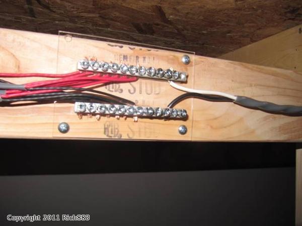
Here is a buss bar for common(similar) connections from another source posted by Dale H. That participates in this forum.

Hope that helps.

Edit: add quote and link:

"While I have used the MTH distribution blocks for the lower voltage distribution in my layout, I decided to build some for the track power. I used Ground buss bars from the electrical department of a big box store, cut it in half while my dremel cutting wheal, and super glued to a piece of Plexiglas I also got there.  I drilled holes in the corners for mounting screws. And for about $8 I had a nice block."


Link is here

Buss_Layout Wiring

Attachments

Images (1)
  • Buss_Layout Wiring
Last edited by Moonman
Post

OGR Publishing, Inc., 1310 Eastside Centre Ct, Suite 6, Mountain Home, AR 72653
800-980-OGRR (6477)
www.ogaugerr.com

×
×
×
×
Link copied to your clipboard.
×
×