
After some discussions with Lionel about the wild difference in the brightness of the number boards in the powered and Cabbage units, we all came to agreement that the powered unit was probably too bright vs. the Cabbage unit being too dim.  After Jon Z. pointed the way, I decided to take a look and see if that could be rectified.

First off, after open the shell, I was pleased to see that the wiring fix was obviously applied.  The lighting board wires are out of the line of fire of the flywheel, that's a good thing.

F40PH Number Board Fix N1

When I got the lighting board out, I could see a lot of residue left from the board manufacturing, so I cleaned that off, it's probably my OCD nature.   Since it was only the thru-hole components, I suspect those were hand-soldered, all the surface mount was clean. 

A lot of lights on this board, the cab lights can be seen on the bottom, and there are seven LED's on the top.

F40PH Number Board Fix N2

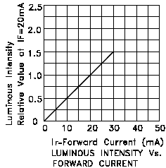
I grabbed the resistor drawer and started trying some values.  I have all the electronics disconnected, and I'm just using on little 1.5mm connector with the leads to the connector for the number boards.  3.9K looked pretty good, it achieved the result I was looking for.  Since that's in series with the 1.0K, that's 4.9K to do the trick.  I didn't have 4.9K, but I do have 4.7K, close enough.

F40PH Number Board Fix N3

Here's the brightness level now, much better!

F40PH Number Board Fix N4

I don't have an "after fix" photo, but it's hard to tell the difference.  You'd just see a 4.7K resistor in place of R10 that is now a 1.0K resistor.  Popped it all back together and it looks much better now.  You do have to be careful as there are still some wires that could be pinched putting the shell on, that would doubtless spoil your whole day.

F40PH Number Board Fix N5

I hasten to add, this is not a repair for the novice.  Nothing especially difficult, but I wouldn't want to be put in the position of recommending something and having you cook an expensive board. 

Attachments

Images (5)
  • F40PH Number Board Fix N1
  • F40PH Number Board Fix N2
  • F40PH Number Board Fix N3
  • F40PH Number Board Fix N4
  • F40PH Number Board Fix N5
Last edited by gunrunnerjohn
Original Post

Replies sorted oldest to newest

The larger the resistor value for a given voltage, the lower the current and the heat.  The resistor value I used results in about .06 watts of dissipation, and it doesn't even get warm. 

LED's are current mode devices, and you control the brightness by controlling the current.  I dropped the current around 5x to the bulbs.  LED's are have fairly linear light output in relation to current.  So, dropping the current 5x dropped the light output around 5x as well.

Attachments

Images (1)
  • mceclip0

i like the idea of digital control of the various leds... but i'm clearly in the minority.  I don't think the HW would be expensive but to do what I want lionel would have to spend money to do it, and then marketing is not clear for getting new sales:  "This new engine now has the option to individually dim or brighten all LEDs through command control -- flickering is even supported.  Imagine the possibilities!   Yes now you can have a dodgy number board on your layout all with the push of a button!"


Just to put a "bow" on this topic, I put both the powered and Cabbage unit on the tracks to see how they looked after the intensity mod for the powered unit.  The Cabbage unit number boards were way too dim for my liking.  Even after the mod to the powered unit dropped the current 5x, the Cabbage unit number boards were much dimmer. 

In for a dime, in for a dollar, so I opened it up and checked out how the number boards were powered.  Turns out they're powered the same as the powered unit, with track power, a resistor, and back-to-back LED's.  When I traced it out, I discovered a 22K resistor for the current limiting!  Yes, that's not a typo, a 22K resistor!   Stands to reason why they're pretty dim, they were getting less than a milliamp of power!  I skywired a 5.6k resistor across the 22k, that worked pretty well.  So, I replaced the 22k with a 4.7k, the same as I used in the powered unit.  I used a lightly larger size resistor, the old one was a 0603 size, I used the 0805 size.  This gives a bit more power handling as it's passing four times the current now.  On this one I actually took the picture after the mod.

This is a different board design, it has a processor managing most of the lights, but not the number boards.  The Cabbage unit also uses a version of the RCDR board and not the full RCMC of the powered units or the other dummies I've worked on.  Interesting tidbit, but not important for the problem I was addressing.

F40PH Cabbage Number Board Fix

What do you know, the two units now have similarly lit number boards, just the way I'd expect, job done!

As before, be aware if you screw something up, you've probably bought it.  The connectors are pretty small and pulling on the wires is the kiss of death many times, so you have to exercise caution.  I use husky tweezers  to work the connectors out.  Obviously, soldering on these boards requires something a little more sophisticated than your typical Weller 100/140 gun as well.

Attachments

Images (1)
  • F40PH Cabbage Number Board Fix

I was looking at these the other day and wondering if they would be better then a regular old magnifying lamp? They are only like $39 so I wonder how good the picture would really be as opposed to the one shown in the ads? Here's a link to one, but there are others out there. I saw a youtube video of someone using one of these, but I think they had a much more expensive one, like maybe several hundred $$.

Last edited by rtr12

Nick, in this case, it was pretty easy.  Once I found out that they were track powered, I just had to locate the resistor and install the correct value.  As I said, the hardest part is getting to the resistor, you have to be careful with the little 1.5mm connectors, the wires are small and break easily if you yank on them.  For the powered unit, I'm glad I now know the wiring is really out of the way of the flywheel, that's certainly killed a lot of these.  That was the only red flag I saw looking inside.

Some thought was put into the lighting mechanical design on these, most of the lights are on the one board.  I suspect that makes it easier to build and test.

It is interesting that one resistor was too low in value, and the other resistor was too high in value.  There was a 22:1 difference in light output for the number boards between the two units! 

There's an old saying about the right hand knowing what the left hand is doing...

I'm happy with the final outcome, they look like they belong together now.

Someone either goobed the math on the needed resister or fed the wrong resisters into it...  i always thought the surface mount stuff was only done by machine but google shows otherwise.

Still prefer a different way:  the digital pot chips are pretty cheap and have serial line interfaces which is easy...  but no takers.

Since the lighting boards are a different design, I presume there were two bill of materials and a separate run to assemble them.  Obviously, since the number boards were powered the same way on both, they should have had at least the same value resistor you would think.  In any case, mine now have matching intensity on the number boards, and I feel a little better about what's inside having looked them over while they were open.

Add Reply

Post

OGR Publishing, Inc., 1310 Eastside Centre Ct, Suite 6, Mountain Home, AR 72653
800-980-OGRR (6477)
www.ogaugerr.com

×
×
×
×
Link copied to your clipboard.
×
×