With the DCC discussion that started in the MTH no more remote thread, I thought it'd be good to answer the questions asked here as a mod asked the thread to stay on topic.

MTH PS-3 locomotives can also be run with DCC.  You will get all the core DCC functions that are part of the standard.  There are some DCS functions that you will not get, this is due to DCS having more options then DCC.  This video of Mike Wolfe talking about it is a good watch for DCS/DCC (Thanks to Trainworld.).

As for command sets to buy, NCE makes a command set for O gauge, the PH-10.  Wired is about $800 and wireless $1000 from them.  It can be had for less online.  They also sell a power supply, but it is not needed on a current layout.  You can use your ZW or Z-1000 to power the NCE system, or any other AC transformer.  Sorry, I do not know if there are other brands that build command systems for O.

Some things to keep in mind with DCC.  You can not run your whole layout from one command set.  You need what are called boosters.  You need a booster for each channel of your TIU you are replacing.  So if you need all 4 channels of your TIU, then you need 4 boosters.  Basically you need a booster for each power district you have.  The NCE 10 amp booster is about $320 each, again cheaper if you look for it online.

As for configuration of your MTH locomotive, MTH does have a list of the CVs in the manual.  I can't link to an example as their site is down currently, but NCE does have some information here.  The function list and default setting for MTH DCC can be found here.

This is about all I can answer on the subject as I don't currently have any MTH locomotives.  I do have the NCE 10 amp command set and have converted a conventional locomotive to DCC with a LokSound L decoder.  Once it's done my layout will be switchable between DCC and Legacy/TMCC as you can't run them at the same time (See my thread about running them together.).

Original Post

Replies sorted oldest to newest

I currently have 4 MTH PS3 GP40's that I run under DCC. Back when I was in 3-rail I used to run DCS and I have to say that PS3 locomotives under DCC run just as well as they do with DCS. Other than no proto-couplers, DCC activates all of the features that DCS does. I prefer DCC over DCS because there are no annoying "Check Track" or "Engine Not Found" messages.

I have an NCE PH10R which is the wireless command set which includes a 10 amp booster. When I build my layout next year I will get another 10 amp booster and "Brutus" power supply - 2 boosters/2 loops, 1 command station.

Good info, thanks! I knew the prices of the NCE starter systems, but Ouch on the boosters. I'd never looked at those before or considered needing more than one. It was just mentioned on the other thread to take a look at the new ESU remote system, not sure I have seen that one? I have been sold on the NCE system for a few years, just haven't bit the bullet on purchasing one as I already have DCS and Legacy.  

catnap posted:

I currently have 4 MTH PS3 GP40's that I run under DCC. Back when I was in 3-rail I used to run DCS and I have to say that PS3 locomotives under DCC run just as well as they do with DCS. Other than no proto-couplers, DCC activates all of the features that DCS does. I prefer DCC over DCS because there are no annoying "Check Track" or "Engine Not Found" messages.

I have an NCE PH10R which is the wireless command set which includes a 10 amp booster. When I build my layout next year I will get another 10 amp booster and "Brutus" power supply - 2 boosters/2 loops, 1 command station.

That's the same reason I like DCC so much. When I issue a command the locomotive responds. Pretty much every time. The once in a rare while it doesn't respond is because it hit some dirty track. No command system will work with dirty track except the Dead Rail stuff. 

I bought the NCE system about 10 years ago. It was cheaper back then. I later on upgraded the system to radio and then I added the Brute. I only have one Booster. I am glad I waited on the radio option because the original NCE radio equipment was not good. They re-engineered their radio stuff and now it is bulletproof like the rest of the system. 

"You can not run your whole layout from one command set." This is not entirely true. Smaller layouts will only need the one Booster. I used to belong to a club that ran this system. They have a very large layout about 60' by 30' with large mainlines. I am not sure how many boosters they have but I don't think it is more than 3 or 4 but this is a large club layout. I can't picture home layouts needing more than 2 or 3 at the most. This is due to 2 rail or 3RS usually having larger curves and thus more of a scale themed track plan where less is more. In a scale atmosphere you usually do not see a spaghetti bowl track plan where the user tries to fit in as many loops as possible. Nothing wrong with those layouts just stating the difference. However you are correct in stating the Boosters are not cheap. Thank God they are a one time expense. 

OTOH, if someone wanted to build a toy train layout with a lot of smoke and incandescent lighting it could really get expensive with the boosters. 


Last edited by Hudson J1e

My command station came from NCE set at 16.5 volts. Apparently, the NMRA recommends about 16 volts for running O scale on DCC. There is a potentiometer inside that can be adjusted to increase voltage up to 18 volts if necessary. I don't have any lighted cars except for the occasional caboose so 16.5 volts is optimal for my 10' X 30' temporary layout.

I'm going to have 2 loops inside my garage. It's going to be 14' X 19' so I'll add a 2nd booster for the other track. One booster/power supply per loop will provide more than enough power.

30 amps and 24 volts sounds like overkill. I guess if I was pulling heavy trains with lots of lighted cars that may be a consideration.

Catnap, like you said it will be more than enough power. If you only have two loops and no incandescent lights one booster will be fine. You can also break a layout into districts by adding circuit breakers off of one booster. In other words you could put a circuit breaker for each of your loops with power coming from the same booster. This way if there is a short or derailment on one loop the other loop will not shut down. Just a suggestion. 


Trainlover9943 posted:

I have a 4' by 16' layout. I'd use the PH-10R. I have legacy already installed on my layout (Have DCS too but would get rid of it in favor of DCC). I'm using an MRC Pure power transformer. What do I need to buy? A booster? 

If you purchase the PH-10R it comes with one booster. That system alone might be enough for your entire layout. It depends on how many locomotives you run at the same time and how many incandescent lights you have running off of track power. As long as you have some sort of power supply like a Z4000 you will have everything you need to run the DCC system.  If the PH-10R doesn’t provide enough power you will need a second booster and another power supply. 

Hudson J1e posted:
Trainlover9943 posted:

I have a 4' by 16' layout. I'd use the PH-10R. I have legacy already installed on my layout (Have DCS too but would get rid of it in favor of DCC). I'm using an MRC Pure power transformer. What do I need to buy? A booster? 

If you purchase the PH-10R it comes with one booster. That system alone might be enough for your entire layout. It depends on how many locomotives you run at the same time and how many incandescent lights you have running off of track power. As long as you have some sort of power supply like a Z4000 you will have everything you need to run the DCC system.  If the PH-10R doesn’t provide enough power you will need a second booster and another power supply. 

Cool. I'd guess that my MRC should be fine. I've converted all my passenger cars to LEDs. I take it too many smoke units could be a problem due to them taking up amps? 

catnap posted:

Other than no proto-couplers, DCC activates all of the features that DCS does.

It was my understanding that the couplers would open with DCC command, is this not the case?

As for setting the voltage of the NEC booster, I did set mine to 18V so that there wouldn't be any issues as I will still use Legacy to control power to the sidings and throwing turnouts.

And about how many boosters you'd need, like I said in the top post, if you are replacing DCS you'd want one for every channel you use on the TIU.  And for Legacy one booster for every power supply (PH-180/135) you have or handle on a ZW.  My layout is planned to use 3 handles of my ZW, so that's 3 boosters.  This is one of the reasons I'm going with NEC as they have 10 amp boosters, and 10 amps is what the ZW does per handle, and I believe the TIU does per channel, so I didn't need to do any more figuring.

And as for command sets, yes, you only need one, but big layouts will need more boosters.  Boosters are not command sets, they only relay the command signal from the command base.

I've been running DCC on a large (as in, the entire first floor of my house) layout for about five years now, so I can clarify a few things here.

For starters, the wireless 10 amp NCE system is available for $600 from places like Tony's Trains. The set includes everything you need except the power supply. I recommend this one, for $90, from mouser. It is small, fanless, and plenty powerful. So $700 to get going with a fully functional wireless 10 amp system.

You do not necessarily need multiple boosters. I run my entire layout with a single booster, and that's with plenty of engines running, pulling 20-30 car trains, powering all accessories, lights, etc. off the booster. I am typically running about 5 amps DCC output during a normal operating session. Multiple boosters are handy if you want to subdivide your layout (for example mainline vs, yard), so that a derailment in one section doesn't bring down another section, or for very large layouts. But the starter 10 amp booster will be more than adequate for most.

The NCE remote is very nicely laid out and easy to use. All the standard MTH PS3 functions - smoke, couplers, lights, all the sounds, etc. can be controlled via DCC. It's all quite well documented in the MTH manuals. Programming and setup is somewhat easier if you use JMRI along with the NCE, but it is not necessary.

The NCE system integrates nicely with JMRI for control and automation as well, so you have all the options imaginable as far as using tablets, smartphones, and touchscreen laptops for controlling the layout, automating routes, and other whiz-bang. I have JMRI set up with a full graphical representation of my layout that is controllable wirelessly via laptop and ipad. It's a lot of fun using the ipad in conjunction with the remote for heavy duty yard operations, etc. I think I have some posts somewhere about my JMRI setup.

Related rant: Smartphone/app/whatever control is simply not an option IMO as the primary control input for a system where real world hardware can be damaged if you lose control. I don't want to by typing in a passcode, waiting for my phone to update, closing out whatever popup is up at the moment, etc. while a train is running off the track. There's a reason nobody operates industrial machinery like cranes with a smartphone...

sinclair posted:

It was my understanding that the couplers would open with DCC command, is this not the case?

I operate MTH scale wheel locomotives so they don't come with electric coil couplers. The coupler sounds will play when the appropriate key is pushed. I suppose hi-rail locomotives operating on DCC will have functional protocouplers.

catnap posted:
sinclair posted:

It was my understanding that the couplers would open with DCC command, is this not the case?

I operate MTH scale wheel locomotives so they don't come with electric coil couplers. The coupler sounds will play when the appropriate key is pushed. I suppose hi-rail locomotives operating on DCC will have functional protocouplers.

Ah, that makes sense as I had just checked a manual and it said opening couplers.  I've never looked at the manual of a scale wheel locomotive, so I didn't realize they didn't come with proto-couplers.  That's good to know information.

Let me amplify THOR73's sound advice - I've been operating a large (2200 feet of track, 124 turnouts) O scale 2 rail layout for 13 years driven by a single NCE command station and 7 wireless ProCabs.  Initially I powered the  entire layout with one 10 amp booster.  As operations intensified I  later subdivided the railroad into 2 power districts, and still later 4 power districts - each with its own 10 amp booster.  In the coming year I'll I further subdivided one of those power districts into 2 sub-power districts each with its own breaker to isolate operations in the yard and engine terminal from that of the adjacent main line.  

I recommend starting with one 10 amp booster and installing additional ones if the combined power draw you experience in actual operations gets close to the capacity of the system.  No harm will come to the NCE system if the draw exceeds the boosters 10 amp capacity - it is designed to safely shut down before damage is done.  I use DCC Specialties RRampmeters on the output of each booster to observe actual current drawn during operating sessions.  These digital meters are designed to accurately measure the pulse width modulated DCC wave form (analog AC meters designed for sign waves provide less accurate readings).  Each power districts is further protected by DCC Specialties PSX PowerShield fast acting digital circuit breakers.  They self reset when the short is cleared (such as a when an operator forgets to align a powered frog turnout).

  There are at least 3 reasons to subdivide the railroad into multiple power districts -

A - real world peak current draw exceeding 10 amps necessitating additional boosters to divide the load.

B- power district track bus wire runs exceeding 75'  from the booster.  With careful location of the booster(s) relative to track arrangement  one can often mitigate bus length.  In a simplistic example if you have a 150' point to point run locate the booster in the middle of the route.  In the case of very large layouts with multiple boosters they are typically spread around the layout.  Note that multiple track busses can fan out from the booster.  I must confess that my bus runs were initially far longer than the recommended 75' length - I had no operational issues other than perhaps a slight slow down at the most distant point from the booster due to voltage drop.  

C- Minimize interruptions due to derailments/shorts when running multiple trains on separate parts of the railroad.   ( eg a derailment in the yard impacting trains running on the main or branch line.  If current draw (factor A) doesn't require an additional booster, you can mitigate issue C by splitting the output of a booster into one or more sub-power districts each with its own digital circuit breaker.  

Allow me to further endorse the NCE DCC components.  They were designed to handle our O scale environment - perhaps in part due to the owner being an O scaler!  I've found that the components stand up well to use - (my command station and first throttle are over 20 years old.   Over that time NCE has upgraded my components (like the wireless throttle)  with new functionality/features as they became available. One relatively new product is their 2 amp self contained PowerCab.  It is a complete DCC system in one hand held package that includes the functionality of a throttle, command station, and a 2 amp booster.  Standing alone it can run a modest single locomotive operation.  I initially use mine to program/test  locomotives on the workbench away from the railroad.  I later sent it to NCE for a $90 radio upgrade.  When not being used on the workbench test track, during operating sessions one the railroad we use it in wireless mode alongside the other NCE cabs - same form/fit/& function. 


Agree with all of Ed's comments above, particularly concerning the robustness and upgradeability of the NCE hardware. It definitely has an industrial strength feel and performance to it.

Expanding on the DCC breaker option a bit (which completely slipped my mind in my earlier post) this is a great way to create multiple power districts powered by a single booster. Better and much cheaper, really, if you're not actually limited by the booster power.

I use the same breakers Ed mentioned, the DCC Specialties Powershield PSX1 breaker. I get mine from Tonys Trains for about $40, so they're pretty economical. It has a configurable trip voltage, so you can tailor it to the specific needs of the power district it's driving. The trip and reset behavior in my experience is quite a bit gentler to engines than the booster reset. It is addressable as a standard DCC accessory decoder, so you have remote on/off control of every power district from your cab. I found this to be a surprisingly useful feature when I first started using them, making it really easy to power on blocks of accessories, turn off idle passenger cars in a siding, and so on.

The reset behavior is configurable as well. The auto reset as Ed describes is one option, and in fact has an adjustable retry delay as I recall. Another option, which is what I use, is a manual reset. This allows me to go find and fix whatever happened, without the breaker (or booster, if you don't use a breaker) continually trying to power up and tripping again. Then once I unpile the cars    I can turn the power back on manually with a command from the remote.

That 2amp self contained PowerCab is what my brother got for N gauge and what sold me on NCE.  My layout is small enough that I could probably get away with one booster, but since I have it set up for 3 handles on my ZW I wanted to use three boosters for simplicity in wiring.  Plus I could run a total of 6 locomotives at once if I set it up right, and that would be pushing the booster at the edge.  So with how I have it planned, it should only see a max of 3 engines per booster with a rare 4th.

May 2023 Update (4 years later): This April 2023 video https://youtu.be/pdaZyY0dnF0   shows 3 MTH trains on the same mainline, no blocks, 1 detector.

1. FYI: Experimenting With NCE Power Cab & Proto 3 Alco

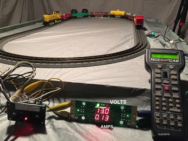
  • I have been experimenting (blundering?) with running the MTH Premier Proto 3 Alco S2 shown in the 1st photo, using the NCE "Power Cab".
  • This seems to work. The loco pulling 7 cars, draws around 1.25 amps.
  • The Power-Cab is fixed at 13 volts, and with the "as delivered" 1.35 amp power supply will provide up to about 1.35 amp.
  • .     (According to the NCE 'ZenDesk', it is rated for a continuous maximum of 2 amps, and a short term peak of 3 amps.)
  • ~~~
  • This Power Cab would probably be considered very "BORDERLINE" -- due to it's limited amperage and lower voltage.
  • But for a small engine like this S2, and a not-too-long train, and running not-too-fast -- it might work (such as for around a Christmas tree).

Voltage Drops

  • When actually pulling the train, that 13 volts seems to drop down to around 12 or 11 volts.
  • When the voltage drops below 11 volts, then the loco seems to start "jerking".
  • .     ((If I use my larger 5 amp NCE "Power Pro" system set at its maximum of 16 volts, I don't observe the "jerking" problem.))
  • .      ((FYI: Using my 5 amp NCE "Power Pro" system, and holding my hand in front of the loco to "stall" it -- my DCC "RRampMeter" says the loco is pulling over 3 amps.))
  • ~~
  • Due to its current and voltage limitations, I can NOT recommend spending the $160-$180 to buy a new PowerCab.
  • But if you already have one, or can borrow one from a friend, it is something you could experiment with.

(text CONTINUES below 1st photo)

5442-pcab+rrAmpMtr1600

O27 Problems: This S2 loco does not seem to want to go around O27 curves, as shown in the photo below (I need to learn more about this). The photo above shows it operating on MTH O31 Realtrax. (MTH says it needs O31 minimum curve, even though it's the same 12" length as the SW9s/SW1500s, and the catalog says the SW9s operate on O27.)

2. Notes About The DCS/DCC Switch

(as I understand it)

  • As I understand it, ALL MTH Proto 3 locos have decoders capable of running on both DCS or DCC.
  • But not all of them come with the DCS/DCC switch on the bottom.

The Switch:

  • When Proto 3 came out in approximately 2011, all Railking and all Premier locos had the DCS/DCC switch.
  • All Proto 3 Premier locos still have that switch (2011 to present).

However, around 2014, the switch was REMOVED from the Railking locos.

  • The decoders in the post-2014 Railking locos that don't have the switch, are still capable of running on DCC, but you have obtain the parts (the switch & 2 screws) and ADD the switch yourself (or have someone talented do it for you).
  • MTH has a 2-page PDF instruction sheet showing how to do this.
  • Alternately, there is a jumper wire inside the loco that you can just CUT -- and then the loco with run on DCC, but will NOT run on DCS.
  • Said another way, apparently that switch "opens" that jumper wire connection to run on DCC, or "closes" that jumper wire connection to run on DCS.

3. I'm Working On A VIDEO of This:

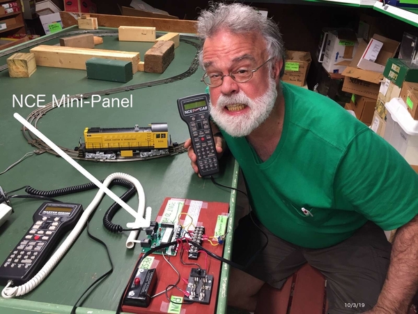
  • I'm trying to make a VIDEO -- showing the NCE "Mini-Panel" (shown in below photo) controlling this loco AUTOMATICALLY
  • Preliminary testing leads me to believe we can do it.

More FYI, re Previous Videos:

  • Under the 'AutoControls.org' video series, I have made a bunch of videos showing automatic control of N/HO/S and Largescale trains, but not yet O gauge.
  • FYI #3: There's a "compilation" video  that shows some of setups operating.
  • This link https://youtu.be/le6Bsz66ndo?t=410  should take you to the 6:50 minute point in that video, where the DCC part begins (the 1st part of the video is analog).  Note this video is FAST FORWARDED.  (It's a compilation of 18 videos.)

5435-s2+jim1600

Attachments

Images (2)
  • 5435-s2+jim1600
  • 5442-pcab+rrAmpMtr1600
Last edited by James Ingram

A friend was interested in the MTH ES44 Hybrid in 2-rail, but he ran an NCE DCC 10-amp system. I brought out mine (2-rail/Proto-3) to a show where his modular group was operating. It ran flawlessly and he immediately ordered one, plus a Blue Goose Hudson. Pretty much all of the standard features run under DCC, but some specialized DCS functions indeed do not. It really comes down to whether you need those features. I've been looking at 5-amp DCC systems to support a couple of 2-rail only locomotives I have running under DCC and I would probably use some of my Proto-3 locomotives with it as well.

@AGHRMatt Does a PS3 loco "coast" to a gentle stop under DCC if you press "Direction" while it is rolling along at a good clip?  Is this a user-adjustable DCC configuration variable?  Likewise, the adjustable rate of acceleration.  DCS has had adjustable max rate of acceleration from the beginning.  Does the PS3 board offer it as a programmable CV under DCC?  Sorry for all the questions!  -Ted

Last edited by Ted S

I operate PS3 locomotives under DCC with my NCE 10-amp ProCab. You get all of the features under DCC that you do with DCS. All 29 functions are mapped. You can adjust the speed curve and acceleration settings on a PS3 locomotive just like you would with any other locomotive with a DCC decoder. MTH provides a manual with all of the values for the CV's that you want to rewrite.

Why on earth would you want to change directions with a locomotive in motion? That sounds like a recipe for disaster to the running gear and motors.

catnap posted:

I operate PS3 locomotives under DCC with my NCE 10-amp ProCab. You get all of the features under DCC that you do with DCS. All 29 functions are mapped. You can adjust the speed curve and acceleration settings on a PS3 locomotive just like you would with any other locomotive with a DCC decoder. MTH provides a manual with all of the values for the CV's that you want to rewrite.

Why on earth would you want to change directions with a locomotive in motion? That sounds like a recipe for disaster to the running gear and motors.

Do you get the quillable whistle on steam when on DCC? 

Yes, DCC supports what is called "Playable Whistle" or "Playable Horn" in DCC parlance but it is only available on sound decoders that have this feature built in, which most of the major current DCC sound decoder suppliers (Soundtraxx, ESU Loksound, TCS) do now support.   

Not sure if this supported under MTH PS3 decoder though.  

Scott

Last edited by Scott Kay
catnap posted:

Why on earth would you want to change directions with a locomotive in motion? That sounds like a recipe for disaster to the running gear and motors.

I wouldn't.  But with the right programming it might be easier than decreasing the speed with the thumbwheel, no less realistic, and also not damaging to the drive train.  Please keep reading...

From the beginning PS3 has had an issue with abrupt stops, whereas the prior MTH control boards (PS2) did not.  Even mechanical momentum from the flywheel doesn't seem to overcome it.  Some have suspected a programming (firmware) error.  If PS3 locos exhibit this same abrupt stopping behavior under DCC, that suggests the issue extends beyond the DCS firmware to the hardware on the motor driver board.

For a long time I was active with a modular group that displayed to the public several times a year.  Sometimes we would let kids run the trains.  And sometimes, either deliberately or accidentally, a kid would press the DIR button while the train was running.  (On the proprietary 3-rail command systems, there is no way to lock out the DIR function without seriously modifying the hand-held controllers.)  The default programmed behavior for DIR was to decelerate the train at a gradual programmed rate to a full stop, and wait at speed step zero, primed to run in the opposite direction when the throttle control was advanced.  No harm done.  That's convenient, logical, and also what I would prefer with DCC.

So what's the default behavior of a PS3 board under DCC?  Does it stop gradually or abruptly?  And can it be configured to behave as I describe above?  Thanks!!

Last edited by Ted S

20-20899-1

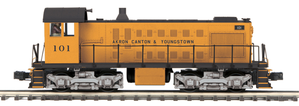
My Akron Canton & Youngstown Alco S2 Has Gradual Stopping:

  • This PS3 Akron Canton & Youngstown Alco S2 that I have been experimenting with (picture shown in my Oct. 7 post above), seems to have "gradual slowdown" built into it when operating on DCC.
  • For example, if I instantly change from Speed Step 10 down to Speed Step 0 (stop) , the loco GRADUALLY slows down.
  • It also gradually accelerates when starting up.

Pushing Direction Button While Running

  • I also frequently press the "Direction" button when the loco is travelling fairly fast (why: because I'm a lazy operator &nbsp.
  • When I do this, the loco gradually slows down, sits for a second, then gradually starts up in the other direction.
  • .     (All other brands of DCC decoders that I have encountered, behave this same way.)
  • If I need  to stop the loco instantly (due to a derailment or something I forgot that I left on the track), I just press the "Emergency Stop" button-- which stops it almost instantly.

FYI: The CVs

  • I have not yet tried to change the contents of CV3 (acceleration) and CV4 (deceleration).
  • I tried to read them using the Power Cab in programming mode, and their contents appeared to be 0.
  • That setting SHOULD be "instant stop" -- but as I said, this loco always seems to start and stop gradually.
    ~~~~~~~
  • Keep in mind, this loco that I have is from the 2018 ver 1 catalog, so it might behave differently then other vintages of PS3 locos.
  • This is the first O gauge "Proto" (digital) loco I've owned, and  I've only had it for about 3 weeks -- so I'm "learning as I go".)

Attachments

Images (1)
  • 20-20899-1
Last edited by James Ingram

My issue with MTH DCC locos is if you change the motor control to MWH not sMPH that you lose sounds such as brake sounds when you slow down the trian to scale speed. I have seen this on my 4 MTH HO engines with PS3. They run great just not gonna touch MTH because I do allot of consisting and to do that i need MWH control CV52=1 and do not want to lose sound features. Plus the fact that MTH is going out next year. I will continue to buy used MTH O scale pS2/3 products though love them.

Last edited by Jamos

Its a DCC issue apparently. MHW is when you want to adjust voltage on three points or when you want to use a speed curve. If you do not need to adjust it your consist will work fine. the only sounds im losing are the brake sounds on deceleration those must be based on sMPH. I would say its a bug but not going to buy MTH HO anymore anyways because I use DCC. I do not want to run my GP38-2 at 100 sMPH top speed is 65 seeing it pass passenger engines is non realistic.

Last edited by Jamos
@Jamos posted:

I do not want to run my GP38-2 at 100 sMPH top speed is 65 seeing it pass passenger engines is non realistic.

Then don't turn the speed up so high.  It's extremely rare for me to run mine above speed step 50 (Using 128 speed steps).  As for break sounds, mine come on if I turn the throttle all the way to zero from anything over speed step 20.  Remember, when in DCC the number on your controller is not sMPH, it's just speed step.  You are right that with most other DCC decoders, you can adjust the speed so that the speed step becomes sMPH, but I do not know if that is possible with MTH.  They do have some speed tables built in you can switch between, but all MTH locomotives are already factory speed matched with each other.

I'd like to add some good info to this discussion, and yes I know this thread is now 2 years old.  First, I'd like to acknowledge James Ingram, who posted above, much of what I've learned about MTH DCC is from him, his site, and his videos.  However, as a long time NCE DCC user, I have some input on how to save a ton of money if you'd like to go DCC with MTH in O scale.  First, I'm mostly a G scale person so I know about pulling a lot of Amps, DCC boosters, and the like. I've also done some research on the actual Amps that get pulled by G scale and O scale engines. Many people WAY over estimate what the engines actually pull.  Example, I hear people say that the 4 motor Aristo-Craft Dash 9, one of the largest G scale engines, requires 5 Amp min.  However, testing shows the actually max current, stall current is around 3.5 Amps.  This was tested in Garden Railways Magazine.  I have sucessfully run 2 G scale SD-45s on one 5 Amp / 24v DCC booster at fairly high speed steps before the booster hit its limit.

Ok, onto my tips.  First, you can use ANY DCC system with O or G scale, you just need a booster along with the command station that has the right voltage and current specs.  For O scale I recommend at least one 5 Amp booster at 16-18V.  I use an NCE Powercab System, that I bought about 13 years ago for $125, they are now about $175.  With that I've tried several boosters including a Bachmann 5A, two MRC 8A, and a custom MRC 8A booster that was modified to make two 6 Amp boosters (don't ask me how, someone else did it)  and more recently the best bargain in the world.... Tam Valley Depot 5A boosters that cost only $50 or so, without a power supply.   I'll get a photo below of my setup with the 5 Amp Tam Valley booster, I mounted everything on a board along with an NCE Mini-Panel for DCC train automation.  My point is that you can have a fully functioning O scale DCC system for about $250-$270.  I also have a 2nd NCE DCC ProCab as a 2nd throttle, and also use it as an easier way to program my NCE Mini-Panel.  I buy many of my items used, my Procab was only $100 on eBay.  As a matter of fact, I just purchased another NCE PowerCab system this week on eBay for only $130 with shipping!  Now I'll have two completely separate DCC systems for O Scale and G scale, I've been switching back and forth these last few weeks.

Power supply selection.  For G scale I can get 2 24v 6A power bricks on Amazon for only $23, yes TWO.  I use one to power Tam Valley Depot Booster, with just under 24V to the track.  For O scale this week I've been using an adjustable 5-24V 3A power supply (I'm about to purchase a 5 Amp model that goes for about $30 ) for testing etc.  I can run 2 O scale engines with this, but it has cut out some since I reached 3A limit.  I just have to reset everything when that happens, but no damage to the power brick.  I set the power supply to just above 16V so I get about 16V AC to the Track from the booster.  I spent much of the last several days testing 3 Railking MTH engines I just bought on eBay in DCC mode, all run GREAT with lots of nice options.  I have a 4th engine on the way.

Like James Ingram, higher up in this thread, I build many Auto Control circuits in both Analog DC in G scale, and now working on DCC in G scale and O scale.  BTW,  I can also run Lionel Lionchief engines on the DCC track along with the DCC locos, I just use the lionchief remotes (or Lionel App) to run those independently.  Today I was running both an MTH 2-8-0 steam engine on DCC and my Lionel Pacific 4-6-2 trains together on my small test layout.  I then had 2 DCC engines running, and 1 lionchief and took turns putting one on the siding and running the other 2.  As long as only a max of 2 were actually running at normal speed I never hit the limit of my 3 amp power supply.  When I get the new 5 amp brick it will be great!

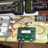
Below is a photo of my entire DCC setup.  The Board is a 1x6 about 13 inches long.  Top right is the Tam Valley Depot 5A DCC Booster, bottom right is the ProCab powered UTP panel, middle bottom is my NCE Mini-Panel used for automation (it's essentially a programmable NCE CAB unit with about 130 memory locations for code, and 30 inputs from detectors, reed switches, buttons or switches.  The box on the left are connected to the Mini-Panel for starting automatic DCC sequences, plus switches for options in the code. This entire setup (with the extra Procab and Mini-Panel) is about a $400 investment, but for full featured DCC you don't need the Mini-panel or 2nd Cab. Also, for larger layouts just add additional boosters for each district.  For most home layouts you should only need about 3 boosters/districts.  Plus, you can get more powerful boosters if needed, but they will cost more.  I'm in the process of building my own 10A booster based on an Arduino, I found the plans online.

Another Note: You don't need to use NCE.  I've also built an Aurdino-based command station, with a Raspberry Pi 4 mini computer using JMRI software, with my phone and tablet as throttles.  It's called DCC++ EX, you can find it on the web. Very inexpensive and works well, I just used my Booster to run my G scale trains with it.  Heck, I used a base Bachamm DCC system I got for $100 back about 10 years ago with my MRC booster, and then Bachmann Booster to run G scale trains too.  Just pick which system you like and you can get cheap.  Right now, IMHO, one of the best out-of-the-box systems with 7 Amp booster built-in is the ESU 50210 CabControl Wireless DCC System with 7Amp booster variable voltage 15-21v.  It is PERFECT for O scale DCC MTH based layout, and runs about $375 total.   Let me know if you have any questions or need more info on anything.

Last edited by T Ansley

I chose an inexpensive entry to DCC.  I purchased a BlueRail board and then decided to power the engine with a battery.

My MTH engines run so much better with BlueRail control and the Blunami app then they ever ran with DCS.  Especially with consisting.

I just recently gutted the PS3 components and installed a Soundtraxx 4400 decoder.  WOW what a difference.

The new Blunami 4400 coming out in 2023 for O and G will basically be the BlueRail board and the Soundtraxx board all wrapped into one.

I have a 44 tonner still running PS3 in DCC mode.  That will eventually get ripped out for Blunami also.

Ron


Last edited by Ron045
@T Ansley posted:

I'd like to add some good info to this discussion, and yes I know this thread is now 2 years old.  First, I'd like to acknowledge James Ingram, who posted above, much of what I've learned about MTH DCC is from him, his site, and his videos.  However, as a long time NCE DCC user, I have some input on how to save a ton of money if you'd like to go DCC with MTH in O scale.  First, I'm mostly a G scale person so I know about pulling a lot of Amps, DCC boosters, and the like. I've also done some research on the actual Amps that get pulled by G scale and O scale engines. Many people WAY over estimate what the engines actually pull.  Example, I hear people say that the 4 motor Aristo-Craft Dash 9, one of the largest G scale engines, requires 5 Amp min.  However, testing shows the actually max current, stall current is around 3.5 Amps.  This was tested in Garden Railways Magazine.  I have sucessfully run 2 G scale SD-45s on one 5 Amp / 24v DCC booster at fairly high speed steps before the booster hit its limit.

Ok, onto my tips.  First, you can use ANY DCC system with O or G scale, you just need a booster along with the command station that has the right voltage and current specs.  For O scale I recommend at least one 5 Amp booster at 16-18V.  I use an NCE Powercab System, that I bought about 13 years ago for $125, they are now about $175.  With that I've tried several boosters including a Bachmann 5A, two MRC 8A, and a custom MRC 8A booster that was modified to make two 6 Amp boosters (don't ask me how, someone else did it)  and more recently the best bargain in the world.... Tam Valley Depot 5A boosters that cost only $50 or so, without a power supply.   I'll get a photo below of my setup with the 5 Amp Tam Valley booster, I mounted everything on a board along with an NCE Mini-Panel for DCC train automation.  My point is that you can have a fully functioning O scale DCC system for about $250-$270.  I also have a 2nd NCE DCC ProCab as a 2nd throttle, and also use it as an easier way to program my NCE Mini-Panel.  I buy many of my items used, my Procab was only $100 on eBay.  As a matter of fact, I just purchased another NCE PowerCab system this week on eBay for only $130 with shipping!  Now I'll have two completely separate DCC systems for O Scale and G scale, I've been switching back and forth these last few weeks.

Power supply selection.  For G scale I can get 2 24v 6A power bricks on Amazon for only $23, yes TWO.  I use one to power Tam Valley Depot Booster, with just under 24V to the track.  For O scale this week I've been using an adjustable 5-24V 3A power supply (I'm about to purchase a 5 Amp model that goes for about $30 ) for testing etc.  I can run 2 O scale engines with this, but it has cut out some since I reached 3A limit.  I just have to reset everything when that happens, but no damage to the power brick.  I set the power supply to just above 16V so I get about 16V AC to the Track from the booster.  I spent much of the last several days testing 3 Railking MTH engines I just bought on eBay in DCC mode, all run GREAT with lots of nice options.  I have a 4th engine on the way.

Like James Ingram, higher up in this thread, I build many Auto Control circuits in both Analog DC in G scale, and now working on DCC in G scale and O scale.  BTW,  I can also run Lionel Lionchief engines on the DCC track along with the DCC locos, I just use the lionchief remotes (or Lionel App) to run those independently.  Today I was running both an MTH 2-8-0 steam engine on DCC and my Lionel Pacific 4-6-2 trains together on my small test layout.  I then had 2 DCC engines running, and 1 lionchief and took turns putting one on the siding and running the other 2.  As long as only a max of 2 were actually running at normal speed I never hit the limit of my 3 amp power supply.  When I get the new 5 amp brick it will be great!

Below is a photo of my entire DCC setup.  The Board is a 1x6 about 13 inches long.  Top right is the Tam Valley Depot 5A DCC Booster, bottom right is the ProCab powered UTP panel, middle bottom is my NCE Mini-Panel used for automation (it's essentially a programmable NCD CAB nit with about 130 memory locattions for code, and 30 inputs from detectors, reed switches, buttons or switches.  The box on the left are connected to the Mini-Panel for starting automatic DCC sequences, plus switches for options in the code. This entire setup (with the extra Procab and Mini-Panel) is about a $400 investment, but for full featured DCC you don't need the Mini-panel or 2nd Cab. Also, for larger layouts just add addtional boosters for each district.  For most home layouts you should only need about 3 boosters/districts.  Plus, you can get more powerful boosters if needed, but they will cost more.  I'm in the process of building my own 10A booster based on an Arduino, I found the plans online.

Another Note: You don't need to use NCE.  I've also built an Aurdino-based command station, with a Raspberry Pi 4 mini computer using JMRI software, with my phone and tablet as throttles.  It's called DCC++ EX, you can find it on the web. Very inexpensive and works well, I just used my Booster to run my G scale trains with it.  Heck, I used a base Bachamm DCC system I got for $100 back about 10 years ago with my MRC booster, and then Bachmann Booster to run G scale trains too.  Just pick which system you like and you can get cheap.  Right now, IMHO, one of the best out-of-the-box systems with 7 Amp booster built-in is the ESU 50210 CabControl Wireless DCC System with 7Amp booster variable voltage 15-21v.  It is PERFECT for O scale DCC MTH based layout, and runs about $375 total.   Let me know if you have any questions or need more info on anything.

Thanks for the extensive and detailed post.  Unfortunately, the pic does not appear.

Also, can you provide a link (or specific product name / number) for the inexpensive power brick you found on Amazon/

@Mallard4468 posted:

Thanks for the extensive and detailed post.  Unfortunately, the pic does not appear.

Also, can you provide a link (or specific product name / number) for the inexpensive power brick you found on Amazon/

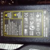
You don't see the big photo of the entire board?  Or..you think I posted a photo of the power brick and you don't see a 2nd photo?  I'll add photos as attachments this time and see if that works.  Which power brick, the 24V 6A one?  I buy those in a 2 pack, I'll post links to the one I use and the one I'm purchasing with adjustable voltage, it's on the way right now.  Here are links to power bricks, first one is 2 for $23 for 24v 5A, the second one is an adustable 4-24V 5A power brick (EDIT: I added a photo of the back of the 24v 6A power brick):

https://www.amazon.com/gp/prod...tle?ie=UTF8&th=1

https://www.amazon.com/gp/prod...le?ie=UTF8&psc=1

Ted

Attachments

Images (2)
  • 5 Amp DCC board with PowerCab, Tam Valley Depot 5A booster, Mini=panel
  • 24V 6A power brick from Amazon (2 for $23)
Last edited by T Ansley
@T Ansley posted:

"......Another Note: You don't need to use NCE.  I've also built an Aurdino-based command station, with a Raspberry Pi 4 mini computer using JMRI software, with my phone and tablet as throttles.  It's called DCC++ EX, you can find it on the web. Very inexpensive and works well, I just used my Booster to run my G scale trains with it.  Heck, I used a base Bachamm DCC system I got for $100 back about 10 years ago with my MRC booster, and then Bachmann Booster to run G scale trains too.  Just pick which system you like and you can get cheap.  Right now, IMHO, one of the best out-of-the-box systems with 7 Amp booster built-in is the ESU 50210 CabControl Wireless DCC System with 7Amp booster variable voltage 15-21v.  It is PERFECT for O scale DCC MTH based layout, and runs about $375 total.   Let me know if you have any questions or need more info on anything.

I know I'm replying to my own post, I'd like to add some info.  First, I stick with NCE, even though I REALLY like some of the new systems like the ESU one I mentioned because.... the NCE Mini-Panel!  That thing is like magic, seriously, if you want DCC train automation it is cheap and works well!  Take a look at all of James Ingram's videos and drawings on AutoControls.org.  Also, look across scales at his videos, pretty much every video and setup he does can be adapted to another scale. I used one of his N scale 2 and 3 train DCC videos and code in my mini-panel for my G scale engines.  I was looking for a way to automate running 2 G scale DCC engines around my modular layout without having to constantly monitor them.  I found with one reed switch, I use an LGB track contact but any reed switch works, and will work in O scale too, I can run 2 trains safely around the layout.  I programmed the mini-panel so that I push a button and one train starts,  then when it crosses the reed switch it slows down, blows its horn and starts and speeds up the 2nd loco.  Then it continues when the 2nd loco hits the reed switch, it blows its horn, slows down and then speeds up the 1st loco. Then it repeats, simple, but very effective and keeps the trains spaced regardless of what brand loco and DCC decoder you use.  You can also do it with 3 locos if the layout is larger.  Yes, it requires some tweaking for each loco you run but it works.  There are many things you can do with mini-panel, throw turnouts, run 3+ trains from sidings.  Pretty much whatever you can fit in the code in 130 steps.  It's essentially an extra Cab on the NCE bus that sends DCC commands according to your code.  You can have plenty of track sensors, use accessories and switches, and send any commands to the locos you would send form a normal CAB.  Yes, there's a learning curve if you have no experience with step-driven commands with logic (sort of like programming light).  However, it really is amazing what you can do with very little hardware and programming.  I just purchased my 4th O scale MTH Rail King engine with Proto-Sound 3.  I plan on fully automating 3 engines running on a simple loop with a siding.  It will be cool, I've already been doing this in G scale for years.  I can post wiring examples, or anything else if anyone needs help,  or how to build this stuff if James' site is confusing to anyone.  However, the original point is that MTH Proto 3 engines are god send to anyone in any other scales that uses DCC, you can simply use the system you already own, and  a booster if needed.

What i don't understand is why other DCC manufacturers haven't added a small mini computer option to their DCC lineup so you can connect and automate sending commands?

I have another tidbit of info that might blow your mind.  You can actually hook the same DCC system to two different scale layouts at the same time!  When I setup an Xmas layout about 10 years ago I had a multi scale layout, the innermost loop of track was N scale, then I had a loop of HO, loop of O and two loops of G.  The N scale loop, HO loop, and outer G loop all ran DCC trains.  I used my NCE PowerCab with Bachmann Booster (at 16V to the track) connected to all 3 loops.  I ran 1 DCC engine on each loop, N, HO and G with different DCC addresses at the same time.  Worked like a charm.   So, in theory I could have two big layouts right next to each other, any scale really, with proper boosters. (with proper grounding, and remember each booster can have different Amps and voltage), I could run both layouts with the same DCC command station!  To make it easier, use one throttle for the 1st scale and the 2nd throttle for the other scale, or just add more throttles if needed! This could easily be accomplished wtih NCE or an Aurdino Based DCC+ EX system w/JMRI computer using phones/tablets as throttles, with multiple power districts.

One last thing.  When I wire my layouts, I had one temp layout with about 7 blocked sections for standard non-DCC wiring, I double block all the sections with DPDT switches, then I can turn on/off completely both rails for any section of the layout,  That way I can have DCC on one side of the DPDT switches and standard Analog on the other and can run either Analog or DCC on any given block at the same time on the layout, usually loops of tracks, or sidings.  This is also a good way to run standard Lioncheif locos and regular O-scale analog on the same layout.  Most people don't have a good understanding of blocking, and when and why you block 1 rail or 2.  Many do understand and do the same, but I've noticed in forums this is complicated for many people.  But, this is a good way to run DCC and Analog on the same layout too. When i take my modular layout to train shows, I typically run DCC on the outer loop and 3 Analog trains on the inner loop, but I can run either.   Wiring is my strength, scenery not so much! :-)

Last edited by T Ansley

To change your engine's Long Address using PoM:

  1. Call up the current engine's address on your DCC handheld
  2. Enter Programming on the Main on your DCC handheld
  3. In this step you have to tell the MTH engine that you want it to start looking at long addresses. You do this in CV29:
    1. Bring up the CV menu on your DCC handheld
    2. Enter “29” to edit CV29
    3. Enter “38” to change the value of CV29 and hit Enter
    4. The engine will give you a two whistle/horn blast response
  4. In the following steps you will now need to write values to CV17 and CV18 to tell the engine what the long address should be
  5. Call up CV17 and enter the value required for CV17. You will get a two whistle/horn blast response
  6. Call up CV18 and enter the value required for CV18. You will get a two whistle/horn blast response

In order to determine your required values for CV17 and CV18 you will need to go download the DCC VC17 and CV18 Conversion Spreadsheet (which can be found on the MTH website or you can use one of the many calculators on line)

Enter in the long address you want then click anywhere else in the spreadsheet and it will return the values for CV17 and CV18 (it will also return the hex conversion of the CV17 and CV18 values if your DCC system requires this).

John, I have done this many times but not in a long time so I had to look up the instructions. There are many on line calculators you can use to find the values for CV17 and CV18. Here is one for example:

https://www.digitrax.com/support/cv/calculators/

You just put in the 4 digit number you want to be the locomotives long address and the calculator will tell you what values to use for CV17 and CV18. Keep us posted.

Last edited by Hudson J1e

John, I think so but I have not used JMRI with MTH PS3. IIRC someone in this thread said they used JMRI with PS3 locomotives.

If you are consisting 2 MTH locomotives you don't have to speed match them it is built in. If you are consisting an MTH locomotive to some other DCC locomotive then you do have to do the speed matching. I believe it can be done but I have never done it.

Easy Way: Changing Address Using NCE 'Program On The Main"

You can do this in just a FEW SIMPLE steps -- without involving any CV's.

This 2:53 long video shows the process:  https://youtu.be/LnYcZHXqW2k .

This shorter 0:58 long video shows the same thing, but without narration:  https://youtube.com/shorts/3Q4A5ircGts?feature=share .

The written instructions are in NCE's help pages article 'Super Easy Programming On The Main (POM)':  https://ncedcc.zendesk.com/hc/...ing-on-the-Main-POM- .

It's actually quite a SIMPLE process --  using this method.


For MORE info, you can search Youtube (or Google) for phrases similar to "how to change loco number using nce program on the main".

Last edited by James Ingram

Sorry for the late response. I agree with James,.no need to program a CV just to set the address with NCE, it's very simple. My PS3 DCC engine are exactly like every other DCC decoder, full featured and just run and program like any DCC decoder. You can do it right in the program on main menu, and just pick ADR option. Takes a few moments, just make sure only 1 engine is on the main when you do it.

Ted Ansley

@T Ansley You mention in your above post "BTW,  I can also run Lionel Lionchief engines on the DCC track along with the DCC locos, I just use the lionchief remotes (or Lionel App) to run those independently."  So just to confirm, you have run Lionchief locos using the dcc for track power without any adverse effects on the Lionchief locos?

Thanks

Bobby

Last edited by Rich Melvin

Yes. DCC puts an AC power signal(ok, it's not technically AC, it's a digital square wave signal) in the track. I can adjust my system, usually I put about 16.5-17 Volts out of my booster, I have an adustable 24V power supply, so I turn it down for O scale. That's the input voltage, that actually track voltage, measured RMS voltage, is probably around 16V.   Remember, the DCC command signals are low voltage digital waves combined with the power signal,  sent out on the rails in conjunction with the the power wave, as if they were signal wires. Everything ignores them on the rails except for the address of the engine receiving the signal. LionChief is an over air system, uses Bluetooth I believe. They don't use the rails for train control. All you need for LionChief is a 16v+ DC or AC voltage on the track, which DCC provides. I've run 2 DCC engines and 1 LionChief many times in my smaller layout.  The LionChief engines simply filter the power to DC, this what they actually use to power the trains.  EDIT: This post was edited to clarify some of the things I mentioned, ie. square wave digital instead of AC, etc. DCC is AC-Like, but not AC.

Ted

Last edited by T Ansley
@T Ansley posted:

Yes. DCC puts an AC power signal in the track. I can adjust my system, usually I put about 16-17 VAC out of my booster.

Remember, the DCC command signals are low voltage digital waves sent out on the rails in conjunction with the AC power wave, as if they were signal wires.

Everything ignores them on the rails except for the address of the engine receiving the signal. LionChief is an over air system, uses Bluetooth I believe. They don't use the rails for train control. All you need for LionChief is a 16v+ DC or AC voltage on the track, which DCC provides. I've run 2 DCC engines and 1 LionChief many times in my smaller layout.

Ted

On another thread Ed Rappe said that DCC was not AC. Like you I always thought it was AC but when I researched it I found that Ed Rappe was correct. I could not find one official place where it states that DCC is AC.

Your second sentence seems to indicate that the command signals are "low voltage" and separate from the power. With DCC the power and the command signals are one and the same. This I am sure of. This is why if a locomotive is touching the rails it is impossible for it to receive power and not the command signals or bit/data or the data/commands without the power. It could hit some dirty track and get nothing so with DCC it is either all or nothing. I have found it to be much more reliable in getting the signal/instructions to the locomotive than either of the proprietary systems.

I think that it is really cool that you can run LionChief locomotives on a track powered by the DCC signal. I assume the LionChief locomotive's electronics are rectifying the DCC signal and turning it into power and then getting their command instructions via the Bluetooth or however Lionel has the remote talk to the locomotive.

The thread I am talking about can be found here:

https://ogrforum.ogaugerr.com/...3#172048746214097773

Here are some highlights from that other thread so you don't have to read the whole thing. (From DCC Wiki)

NMRA Digital Command Control, unlike other analog and digital Command Control systems, puts a 100% digital signal onto the rails, delivering both power and data in the same signal. The digital information is encoded in the time domain by pulse width, not amplitude. It is not superimposed on a DC or AC waveform, nor does it use a high frequency carrier, unlike past and current command control systems. Since the rails are alternately energized or held to zero, there are no issues with polarity.

Since the signal is completely digital, the NMRA Digital Command Control [1] waveform is a square wave. The nature of a square wave results in more demanding requirements for wiring to avoid voltage losses and signal distortion compared to analog control methods.

and...(from NMRA.org)

"The baseline method for providing the power to operate locomotives and accessories, which shall be
supported by all Digital Command Stations and Digital Decoders, is by full-wave rectification of
the bipolar NMRA digital signal within the Digital Decoder. In order to maintain power to the
Digital Decoders, gaps in bit transmission are only allowed at specified times (see S-9.2, Section C)."

From DCC Wiki:

Digital Command Control has no concept of polarity. Binary signals do not have the concept of negative. A negative voltage would be considered an Undefined Value.

The track voltage on an oscilloscope's display indicates the presence of a plus/minus signal. It "sees" a negative voltage when the booster flips the rails, as the reference point is floating. There is no common reference point held to a zero potential. Another way to look at this is how the current is flowing: It will flow from A to B, then B to A. The scope trace will display this.

Last edited by Hudson J1e

Darrell, for many years I thought the same thing.  This is why I didn't believe Ed Rappe on that other thread when he said it wasn't AC. However, I could not find any official source that says it is AC to refute him. Would a regular 60Hz sine wave have a common reference point that is held to zero potential?

Now when it says above that negative voltage would be an undefined value doesn't make sense to me because in the early days of DCC systems there was a way you could control one conventional locomotive with a DC can motor in command mode. I believe the system did this by changing the lengths of the top of the square wave but if you wanted to go in reverse than it changed the lengths of the bottom of the square wave so it had to be getting reversed polarity voltage to go in the opposite direction. I guess it wouldn't be negative voltage just positive voltage but in the opposite polarity.

Then when it says "the rails are alternately energized" this would also indicate to me that it is AC. I don't know, I am not an electrical engineer. The whole thing is very confusing to me. Maybe I was correct all along and it is actually AC and Ed Rappe got some misinformation? It would be cool to clear this up once and for all.

Last edited by Hudson J1e

They are glossing over the details. It is two signals combined into one. Basically it is a voltage square wave power signal (technically not AC as it's a phase changing square wave)  combined with a digital command signal into one power signal. Engineers are specific, so yes, it's not a positive/negative changing voltage sine wave. However, it is a square power wave that combines to zero, it quasi AC-Like, but not AC.  Here's a similar technology that sends signals over power.  Have you heard of internet adapters you plug into a wall outlet that carry internet over your AC power in your house? Basically you plug an internet transmitter into your outlet, with an internet cable attached, then on the other end the internet comes out on a 2nd receiver. Basically, a low power digital signal running on the houshold AC power. This is how DCC works. This is exactly how DCC boosters work. They take a lower power digital signal and combine it with a higher power signal. The low power phase shifting signal has zero impact on the actual power that runs the motor. Did you know that some early DCC systems could run one Analog DC engine? It was a similar setup, but different in that the system would through a DC power signal on the line(rails) just for thatt one DC engine. Those low power digital signals will have zero effect on a lion chief engine. All the Lionchief engine needs is power from the rails. Plus, Lionchief conveniently works on DC or AC. LionChief sends its commands over air, via Bluetooth (early LionChief may not use Bluetooth?), it only gets power for the motor from the rails.

Ted

Last edited by T Ansley

One other thing, the signal on the rails doesn't change at all for forward or reverse! The DCC decoder handles all that. It reads the commands from the command station then the processor in the decoder does the work, it reads the command and will reverse polarity when it is instructed to reverse. A DCC decoder is nothing more than a digital communication device and digital computer. It reads commands, in a specified communication protocol from the rails, then performs an action (basically a small microcontroller then does the action). It also has the circuity to perform the actions, like voltage regulator for output voltage or logic to turn off/on lines like to lights, etc. One more note. Let me clarify some things. Essentially DCC is not AC, because it does not have a negative combined voltage between rails. It is a square wave (not sinusoidal) from 0 to the top voltage ( can vary by scale from 12v-24v). Essentially embedded in that power wave is digital bits sent as phase changes, similar to Modems and other digital communication. However, that power is there and can be measured. If you use an AC meter it will be off by about 10-12% due to square wave vs sine wave. You really need an RMS volt meter. However, the reason it's not important is LionChief engines use a bridge rectifier anyway to convert AC to DC voltage, so any sine wave or square wave will be smoothed out to DC by the loco, as it really runs on DC. Yes, it can be confusing by I'm 99% certain that DCC power is perfectly fine for LionChief and engines.

Ted
Last edited by T Ansley

Thanks guys, I had a feeling the question would bring up the "is dcc ac or dc" subject. I'm not an elec eng either. But since the LC engines (at least the later versions) will run on ac or dc, it seems logical that they could use dcc for power as long as the capacitors after the bridge are large enough to absorb any dc spikes remaining. Thinking about it, I suppose I could have recreated and tested the LC track power circuit on dcc (with a load) to see if there is/was any ripple/noise getting through. It might still be a fun experiment. Anybody know what value caps the laterst LC locos use?

Bobby

NMRA Standard S-9.1 Most definitely describes it as a AC signal.

And I Quote "Digital Decoders shall be designed to correctly decode signals with transitions whose slope is 2.0 volts per microsecond or faster across the voltage range from -4 volts to +4 volts."

This clearly shows Alternating Current, i.e AC

And yes, the rectifier would convert to signal to flat DC anyway so there should be no issues running the lionchief loco's.

@T Ansley posted:

This is how DCC works. This is exactly how DCC boosters work. They take a lower power digital signal and combine it with a higher power signal. The low power signal has zero impact on the actual power that runs the motor.

I am not saying you're wrong but I have never heard it explained that way. Using the word "power" doesn't make sense to me but maybe that is just me.


Did you know that some early DCC systems could run one Analog DC engine? It was a similar setup, but much different, it would throw extra DC on the track for that one engine.

That is exactly what I was trying to explain earlier. The DCC system (I think todays systems no longer do this but I am not 100% sure) would lengthen either the top of the wave for forward or the bottom of the wave for reverse. The problem was that the wave would sometimes overheat can motors or make them whine loudly and I think this is why they stopped trying to control a conventional locomotive (no decoder) this way.


Those low power digital signals will have zero effect on a lion chief engine. All the lion chief engine needs is power from the rails. Plus, lion chief conveniently works on DC or AC. LionChief sends it commands over air, via Bluetooth (early LionChief may not use Bluetooth?, it only gets power for the motor from the rails.

Ted

Agreed on the LionChief. One time I put a MTH PS 2.0 locomotive on a track powered by DCC and I heard a loud whine coming out of the speaker. I immediately turned off the power. No damage occurred to the engine. I decided I didn't want to chance ruining the electronics. I wonder what Lionel does differently than MTH so that you don't hear that same noise in the LionChief locomotives? Most likely a much better rectifier? I guess what is important is that they will work with the DCC wave.

Last edited by Hudson J1e
@T Ansley posted:

One other thing, the signal on the rails doesn't change at all for forward or reverse! The DCC decoder handles all that. It reads the commands from the command station then the processor in the decoder does the work, it reads the command and will reverse polarity when it is instructed to reverse. A DCC decoder is nothing more than a digital communication device and digital computer. It reads commands, in a specified communication protocol from the rails, then performs an action (basically a small microcontroller then does the action). It also has the circuity to perform the actions, like voltage regulator for output voltage or logic to turn off/on lines like to lights, etc. One more note. Let me clarify some things. Essentially DCC is not AC, because it does not have a negative combined voltage between rails. It is a square wave (not sinusoidal) from 0 to the top voltage ( can vary by scale from 12v-24v). Essentially embedded in that power wave is digital bits sent as phase changes, similar to Modems and other digital communication. However, that power is there and can be measured. If you use an AC meter it will be off by about 10-12% due to square wave vs sine wave. You really need an RMS volt meter. However, the reason it's not important is LionChief engines use a bridge rectifier anyway to convert AC to DC voltage, so any sine wave or square wave will be smoothed out to DC by the loco, as it really runs on DC. Yes, it can be confusing by I'm 99% certain that DCC power is perfectly fine for LionChief and engines.

Ted

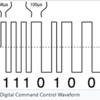
@T Ansley Now you are saying here what Ed Rappe said on that other thread that DCC is not AC but @Darrell is saying that it is AC. Which is the answer? Below is a picture of the DCC Wave form. Assuming the dotted line is O volts how can it not be AC? Here is the definition of AC:

Alternating current, abbreviation AC, flow of electric charge that periodically reverses. It starts, say, from zero, grows to a maximum, decreases to zero, reverses, reaches a maximum in the opposite direction, returns again to the original value, and repeats this cycle indefinitely.

DCC Wave

Attachments

Images (1)
  • DCC Wave

That graph is NOT the actual voltage, that is the digital signal. Read this, it clearly says there is no negative voltage. The digital signal rides above 0 volts. This is a good explanation.

https://dccwiki.com/DCC_Power

Here's an excerpt:

"This is not an AC[15] signal, as the rail will have positive voltage or none at any point in time. What is happening is the current is changing direction as it moves from one rail to another. Measuring this with an oscilloscope will display a peak-to-peak signal, which many will claim supports their assertion that the signal is an AC waveform. Since this measurement is made with the track outputs floating, the trace indicates which connection was more positive than the other at a point in time.[16]


Mathematically, the signal would be expressed as X +jY + X − jY, where X is time and Y is the amplitude or voltage.


This method of transmitting data and power in the same signal results in a very robust signalling technique with a high signal to noise ratio while reducing the space charge around the rails and the electrostatic attraction of contaminants. A multifunction decoder can receive data regardless of the orientation of the locomotive, as either rail has data available."


Ted

Last edited by T Ansley

Two things.  The entire NMRA standard NEVER mentions AC in any of the specs, I have read through them.  It does talk about RS422 communication, and the signal. If, as you say, you've been in the industry then you should understand that a square wave digital signal is NOT AC.  Yes, it looks somewhat like AC, but it is not, it is explained in the link I provided.  Second, the Wiki I linked is referencing the NMRA standard, and much of it is taken directly from the NMRA standard as well.  Again, a square wave digital signal is not AC.   Here's the definition of AC Power: "Alternating current (AC) is an electric current which periodically reverses direction and changes its magnitude continuously with time "  The DCC signal does not meet that definition, it is technically not AC.  I too worked for the Gov't as a Computer Scientist, and Engineering Project Lead, with a degree in Computer Engineering Technology for over 31 years.  I did say in my first post that DCC had an AC component, I was just trying to convey that it was "AC-like", because most people really don't understand digital communication very well.  However, it is NOT AC.

Again, my point in bringing this up was because someone asked about running LionChief engines on the track running DCC.  Regardless of what type of power is supplied with DCC, it works fine with LionChief engines. 

@T Ansley posted:

That graph is NOT the actual voltage, that is the digital signal. Read this, it clearly says there is no negative voltage. The digital signal rides above 0 volts. This is a good explanation.

https://dccwiki.com/DCC_Power

Here's an excerpt:

"This is not an AC[15] signal, as the rail will have positive voltage or none at any point in time. What is happening is the current is changing direction as it moves from one rail to another. Measuring this with an oscilloscope will display a peak-to-peak signal, which many will claim supports their assertion that the signal is an AC waveform. Since this measurement is made with the track outputs floating, the trace indicates which connection was more positive than the other at a point in time.[16]


Mathematically, the signal would be expressed as X +jY + X − jY, where X is time and Y is the amplitude or voltage.


This method of transmitting data and power in the same signal results in a very robust signalling technique with a high signal to noise ratio while reducing the space charge around the rails and the electrostatic attraction of contaminants. A multifunction decoder can receive data regardless of the orientation of the locomotive, as either rail has data available."


Ted

Ted, thank you for trying to explain this. I clicked on your link and read it several times but I am still having trouble fully understanding it. I also read some other information on digital signals but they weren't a whole lot of help. I am not scientist nor an engineer but I would really like to understand how this works.

Okay, I get that the voltage never goes below 0 volts. Does the booster send the signal down one rail and use the other rail for a return or does the booster alternate sending the signal between rail A and rail B? If it does alternate the signal between rail A and rail B at what point in time does it switch rails? Can this be seen on the graph?

"The track voltage has phase, one rail is always the inverse of the other."  What exactly does this statement mean?

Anther thing I found confusing was these two statements at the bottom of the page from your link:

"The 0V reference point is the chassis of the booster."

"The output of the booster is floating, as there is no fixed reference point such as a chassis ground for zero volts."

They seem to contradict one another.

During my research I found this Marklin forum where guys were talking about the same thing we are talking abut here.

https://www.marklin-users.net/...log-on-DCC-Mea-Cupla

Doesn't add much to the conversation but I thought it was interesting to know that we weren't the only ones discussing this.

@Darrell posted:

I hate when you try to help but somebody else just has to be right, no matter what.

Over, under, and out.

Sorry @HudsonJ1e, it really is not this complicated but I will not continue to try and explain this here. Hopefully you will understand some day although it's not vital to just to run trains.

True it isn't vital to running trains but I am just curious to learn how this works. Those guys on the Marklin forum came to the conclusion that it is not AC. I am just trying to get there as well.

@Darrell posted:

I hate when you try to help but somebody else just has to be right, no matter what.

Over, under, and out.

Sorry @HudsonJ1e, it really is not this complicated but I will not continue to try and explain this here. Hopefully you will understand some day although it's not vital to just to run trains.

I'm the one who specifically in my original posts did not go into detail because I was answering the question, yes, about running trains. I was purposely glossing over most of the details. I'm not the one arguing here, but I will supply detailed and correct information if needed.  I did not bring up my credentials until you seemed to find it necessary.  We need to keep things civil, I have zero problems being polite and posting references, but again, I was just answering questions to run trains, not the details of DCC until pressed. I was trying to keep it simple, hence my analogy to running internet signals over power in the house.

Regards,

Ted

Last edited by T Ansley
@Hudson J1e posted:

Ted, thank you for trying to explain this. I clicked on your link and read it several times but I am still having trouble fully understanding it. I also read some other information on digital signals but they weren't a whole lot of help. I am not scientist nor an engineer but I would really like to understand how this works.

Okay, I get that the voltage never goes below 0 volts. Does the booster send the signal down one rail and use the other rail for a return or does the booster alternate sending the signal between rail A and rail B? If it does alternate the signal between rail A and rail B at what point in time does it switch rails? Can this be seen on the graph?

"The track voltage has phase, one rail is always the inverse of the other."  What exactly does this statement mean?

Anther thing I found confusing was these two statements at the bottom of the page from your link:

"The 0V reference point is the chassis of the booster."

"The output of the booster is floating, as there is no fixed reference point such as a chassis ground for zero volts."

They seem to contradict one another.

During my research I found this Marklin forum where guys were talking about the same thing we are talking abut here.

https://www.marklin-users.net/...log-on-DCC-Mea-Cupla

Doesn't add much to the conversation but I thought it was interesting to know that we weren't the only ones discussing this.

I would recommend the DCC Wiki for further reading, and the NMRA DCC standards (however, they are complicated and hard to understand).  You can also learn quite a bit by reading the manuals of various manufacturers.  Also, I don't believe Marklin is fully NMRA compliant, they may be, but I know in the past their systems were had some proprietary changes that weren't, now they might be.  Some of the other European manufacturers also have multiple modes, some that are fully DCC NRMA compliant and some that aren't.  I would also look at JMRI.org, they make great FREE software to run trains using computers.  I personally have JMRI running on a Windows Laptop with a connection via USB to my NCE system, and I also have JMRI running a a small Raspberry PI 4 computer using a home built DCC++EX DCC system.  DCC++EX is a another wonderful way to control trains using DCC, and very inexpensive.  With both of those systems you can use free phone or tablet software to control your trains with DCC.  Maybe that was a bit of information overload, sorry about that. :-)

The main reason I like DCC is it is the defacto Standard, every DCC decoder I have from about 8 or so manufacturers has worked with my 3-4 different DCC systems I've used over the last 15 years, including some non Standard not fully compliant decoders like LGB MTS systems.  I don't like that Lionel, MTH, and other manufacturers keep trying to re-invent and re-do digital train control with their own system, and lock you in.  I do like that MTH was forward-thinking enough to allow full DCC compatibility!  I like the fact that with DCC I can use the same system right now on any N, HO, O 3-rail, and G scale locos I use that have decoders!  I also have some 2 Rail O engines, track, and have setup a layout a while ago. I just purchased some more 2 Rail O scale engines and cars, and I like that I can take the same $160 fully featured DCC Soundtrax Tsunami2 decoders I just installed in 3 of my G scale engines into those O scale engines, and could also put them in 3 rail if I so choose.  It all just works!  One time I had a multi-scale Christmas layout with N, HO, O, and G scale loops of track, I used the same DCC system for all 3 loops of N, HO, and G scale. I just used different addresses on the LOCOs, turned the voltage down to about 14VDC (didn't need high voltage for my G locos if I'm not running them fast), and ran all 3 on the same controller and booster!   That is exactly why DCC is so good, it can run anything in any scale if it follows the standard.  IMHO ALL Command systems should be DCC compatible.

Ted

Last edited by T Ansley

"IMHO ALL Command systems should be DCC compatible."

There's something we do agree on!

Wish I would have found out how compatible DCC was years ago! Lucky for me my Loco roster is only 30 units and 6 are converted to Tsunami 2 4400's so far. It was cheaper to go with the Soundtrax decoders than to install the ERR TMCC, which is far, far, lower in sound and control quality and more complicated to install.

@Darrell posted:

"IMHO ALL Command systems should be DCC compatible."

There's something we do agree on!

Wish I would have found out how compatible DCC was years ago! Lucky for me my Loco roster is only 30 units and 6 are converted to Tsunami 2 4400's so far. It was cheaper to go with the Soundtrax decoders than to install the ERR TMCC, which is far, far, lower in sound and control quality and more complicated to install.

Bottom line, is most people in this thread/topic like DCC, or are curious, otherwise we wouldn't be here discussing it. Also, my Tsunami 2s are 4400s in my 3  latest G Scale engines, and that's what I plan on putting in my new O purchases as well. Great decoders!

Ted

"IMHO ALL Command systems should be DCC compatible."

Ted, I also wholehearted agree!!

I got into O gauge in the late '90s. I built a layout and I used toggle switches for train control. Really, really hated it. I talked to a guy at a LHS. He said you need TMCC which was new at the time. At this time there was no OGR forum or anywhere other than the LHS to get help. I didn't know anyone else into these trains back then. Oh the troubles I had with that system. The constant flickering lights on the locomotive and the crazy crazy intermittent signal problems. I literally was pulling my hair out of head. Then MTH comes out DCS. I talk to Mike Wolf at a LHS and he tells that his system (and I quote him almost word from word) "was derived from [some sort of] military system. It will be VERY ROBUST." That second sentence is word for word. Eventually I got DCS and the same thing. Constant "CHECK TRACK" or "ENGINE NOT ON TRACK" messages and what made it worse was is it seemed I always got these message when a crash was imminent!! A couple of years later I discovered DCC. In my entire time using DCC only once did a locomotive get track voltage and not get the DCC signal. I think the electronics in that engine got temporarily scrambled and it took off like a bat out of ****. A quick reboot of the engine and all was well. But this is ONE TIME in about 20 years! And this what I love the most about DCC. The engine can't get the signal without getting the power and vice versa. It works! I have often said the most important thing to me in a Command Control system is when I give it a command the engine responds and obeys to that command. Now I have had an engine hit a dead spot on the track where it didn't respond but it didn't get any power either so at least no accidents occurred.

I have always said this: All systems have their pros and cons. I do agree the 3 rail proprietary systems do have their pros and they are easier to use, etc. I have wondered recently. Why have the 3 rail systems discontinued their remotes? None of the DCC system manufacturers have done this. I assume if Lionel and MTH can't get the chips for their remotes how do the DCC system manufacturers able to get chips for theirs?

I remember getting into arguments back in the early 2000s because I said Lionel should have started with DCC from the get go. But the answer from the some people was that the technology for controlling a Pullmoor motor with a DCC decoder wasn't available yet. I have never been able to find out if this was true or not. It's what folks said. Maybe they were right? There was a guy York in 2001 selling DCC decoders for 3 rail. His company was called 3RDCC but it didn't catch on because Lionel was building locomotives with TMCC and sound factory installed. He didn't have sound. He had a demo layout showing an engine running under DCC but I don't remember if it had a Pullmoor motor or a can motor. I think it was a can motor.

Anyway, I would have responded sooner but I went away for the weekend with the family. I never meant for there to be any arguing on this thread. I was just trying to learn.

I have read the thread that Darrell references and I agree with Darrell that it is some form of AC. I am not a scientist nor an engineer but I did study electronics in HS. When I first got into DCC I bought a book for beginners. The book is called Digital Command Control by Stan Ames, Rutger Friberg, and Ed Loizeaux. The way Chuck K explains DCC (in the thread referenced by Darrell) is the same way I always understood it from reading that book until the thread where Ed Rappe told me it wasn't AC. I agree with Chuck K's reason for believing it is AC and his two main reasons are that #1) all decoders have rectifiers and why have a rectifier if it isn't AC? and #2) and this is the big thing for me, back in the day when these systems could control one conventional locomotive (just two wires to a motor) by manipulating the DCC signal the system could control speed and direction of that one locomotive. It made the locomotive move by stretching the "0" bit. If it wasn't alternating from rail to rail then the system would never be able to change the direction of the one conventional locomotive. And also in the book I mentioned they do show a drawing very similar to the one I posted and next to the line that I said was Zero volts is "0v". So in my opinion I was right all along in thinking it is a form of AC and it really stinks that because of that other thread I went down this rabbit hole. I do appreciate your efforts in trying to explain it. One last thing I feel the DCC Wiki page is very confusing for a beginner but the book I have explains it so someone like me can understand. I understand you feel it is not AC and that's fine. We just agree to disagree.

" But the answer from the some people was that the technology for controlling a Pullmoor motor with a DCC decoder wasn't available yet. I have never been able to find out if this was true or not. It's what folks said. Maybe they were right?"

Yes, they were right.  Why would Neil Young and Dick Kughn spend the time and money developing TMCC if DCC would have been cheaper and easier?  In the early to mid-1990s you simply could not purchase decoders that had the amperage capacity for AC open frame motors.  There was no need to have them for the can motors used in most 2 rail applications, so no one made them. In addition, the power boosters needed for DCC were both expensive and limited as well.  Not designed for the higher amperage needs of O gauge three rail, and for larger layouts, the expense would be substantial.  Whereas TMCC was designed so that the power and command signal were independent, so existing layouts could be easily and relatively inexpensively adapted to the new system, compared with DCC.

TMCC was actually a cost effective solution to operating three rail AC locomotives and providing decent quality sound (also not available for DCC 25-30 years ago).  Hindsight is always 100% accurate .  But the reality is that nothing commercially available in the mid-1990s in DCC would provide the ability to easily retrofit 75 years of AC open frame motor locos with command control and digital sound.  That's why Young and Kughn developed a new system.

You also have to realize that Lionel has been and still is a toy train company, not primarily focused on the needs and desires of 2 rail O gauge scale modelers.  The priority was on making sure they didn't make it impossible for collectors and operators to operate their previous purchases.  TMCC was (1) available for upgrades through third parties such as Ed Bender's TrainBrain and Train America Studios devices, (2) required no modifications to existing layouts to operate the new TMCC stuff.  In contrast, when MTH introduced PS2 and DCS, they initially failed to provide an upgrade path for PS1 locos, which caused much complaining, leading to a change in policy .

Okay, Landsteiner.

"Whereas TMCC was designed so that the power and command signal were independent, so existing layouts could be easily and relatively inexpensively adapted to the new system, compared with DCC."

Just curious but what does keeping the power and the signal separate have to do with adapting the system to a layout?

"decent quality sound (also not available for DCC 25-30 years ago)"

Not true. 18 years ago I had Soundtraxx sound only decoders and back then they were old tech. Originally they were released in 1998. The sound wasn't great but I would say it was decent.

https://soundtraxx.com/history/

I am not going to argue about this but I never liked TMCC and DCS due to the many, many signal problems I experienced. If you love TMCC and it works for you then I am happy for you. It didn't work for me. I just wish that Niel and Dick would have come up with a better system.

Heck, I remember an article in OGR where a guy was having so many signal problems he actually mounted antennas on top of all his locomotives. It looked ugly but he got the system to work for him. Maybe that isn't the norm but to me it speaks volumes.

Last edited by Hudson J1e

"Just curious but what does keeping the power and the signal separate have to do with adapting the system to a layout?"

With DCC you need to have the power and signal adequate in all areas of the layout.  In 1994 or so, when TMCC was under development, this meant multiple power boosters per layout in many cases. With TMCC, the power was already there on your layout, and you just needed to supply the TMCC signal (command base).  Very simple and adaptable compared with DCC at the time.

""decent quality sound (also not available for DCC 25-30 years ago)"

Not true. 18 years ago I had Soundtraxx sound only decoders and back then they were old tech. Originally they were released in 1998. The sound wasn't great but I would say it was decent."

Not to be too glib, but 1998 isn't 1994. There was no high quality DCC sound in the early to mid-1990s when TMCC and Railsounds were developed.  Those who were familiar with the available sounds felt that Railsounds was much better sound than that available for DCC. Neil Young, who is renowned for being particular about sound quality, felt he could develop a better sound system than that which could be developed for DCC.  Feel free to argue with him if you like .

DCC is neither simple nor problem free all the time, if that's what you are stating.  TMCC is very simple and usually problem free for most people.  The relative lack of magazine articles about TMCC problems over the decades and the multitudes of DCC articles speaks to the complexity and reliability/ease of use of the two systems. Your mileage may no doubt vary, but hundreds of thousands of Lionel customers were and are perfectly happy with TMCC and Legacy (and LionChief).

Perhaps if you are a 2-railer you are living in a different universe and market space? Lionel is not addressing your needs, to be sure.  They have largely kept their customers in mind, which included, back in 1995, 70+ years of three rail O gaugers with large collections of locos with open frame AC motors.   That was their target market.  There were no suitable DCC decoders then for that application.  The power boosters available were expensive and not well suited, which explains why not even gifted individuals were adopting DCC for three rail O gauge. That happened after TMCC was developed.

Last edited by Landsteiner
@Landsteiner posted:

Not to be too glib, but 1998 isn't 1994. There was no high quality DCC sound in the early to mid-1990s when TMCC and Railsounds were developed.

DCC is neither simple nor problem free all the time

You didn't say "High quality sound" You said "decent quality sound ". I agree with you at the time RS was better.

Never said that. What I said was: "I have often said the most important thing to ME in a Command Control system is when I give it a command the engine responds and obeys to that command. That's what I get with DCC. As I said I have one time in 20 years that a locomotive got power without the signal compared to literally hundreds of times this has happened TO ME with the 3 rail proprietary systems and I didn't have these systems that long! Imagine if I was still running them today how many times the signal would not have gotten to the locomotive? I also said many times that all 3 systems have their pros and cons. One of the pros of your system is that it is easier to use than DCC. I have never said otherwise but I will take the DCC learning curve for getting that command to the locomotive RELIABLY ANY DAY over the ease use of use of TMCC.

"Your mileage may no doubt vary, but hundreds of thousands of Lionel customers were and are perfectly happy with TMCC and Legacy (and LionChief)."

My mileage did vary. While I highly doubt it is that many people as from articles in OGR most guys run conventional and I don't count Lionchief because that system works differently than the original TMCC and I have used it and it is more reliable than the original TMCC.

But let me say yes, you win your control system is better than mine!! Enjoy it as I will undoubtedly enjoy mine.

Last edited by Hudson J1e
@Hudson J1e posted:
I will take the DCC learning curve for getting that command to the locomotive RELIABLY ANY DAY over the ease use of use of TMCC.

"Your mileage may no doubt vary, but hundreds of thousands of Lionel customers were and are perfectly happy with TMCC and Legacy (and LionChief)."

Oddly, I find TMCC/Legacy to be very reliable, and I've run it on many layouts.  While DCS has some neat features, it is certainly a bit more challenging to get first-time, every-time results from the remote, I'll agree there.  LionChief and BlueTooth have been way less reliable for me, so I guess my mileage most certainly does vary.

Add Reply

Post

OGR Publishing, Inc., 1310 Eastside Centre Ct, Suite 6, Mountain Home, AR 72653
800-980-OGRR (6477)
www.ogaugerr.com

×
×
×
×
Link copied to your clipboard.
×
×